CN111663249B - Production and manufacturing process of environment-friendly melt-blown fabric - Google Patents
Production and manufacturing process of environment-friendly melt-blown fabric Download PDFInfo
- Publication number
- CN111663249B CN111663249B CN202010569374.0A CN202010569374A CN111663249B CN 111663249 B CN111663249 B CN 111663249B CN 202010569374 A CN202010569374 A CN 202010569374A CN 111663249 B CN111663249 B CN 111663249B
- Authority
- CN
- China
- Prior art keywords
- melt
- rotating cylinder
- cavity
- cooling
- blown
- Prior art date
- Legal status (The legal status is an assumption and is not a legal conclusion. Google has not performed a legal analysis and makes no representation as to the accuracy of the status listed.)
- Active
Links
- 239000004744 fabric Substances 0.000 title claims abstract description 82
- 238000004519 manufacturing process Methods 0.000 title claims abstract description 39
- 238000001816 cooling Methods 0.000 claims abstract description 50
- 238000009434 installation Methods 0.000 claims abstract description 22
- 238000004140 cleaning Methods 0.000 claims abstract description 21
- XEEYBQQBJWHFJM-UHFFFAOYSA-N Iron Chemical compound [Fe] XEEYBQQBJWHFJM-UHFFFAOYSA-N 0.000 claims description 28
- 239000000835 fiber Substances 0.000 claims description 21
- 238000007664 blowing Methods 0.000 claims description 19
- 230000007246 mechanism Effects 0.000 claims description 19
- 230000000694 effects Effects 0.000 claims description 17
- 229910052742 iron Inorganic materials 0.000 claims description 14
- 239000000155 melt Substances 0.000 claims description 12
- 238000007789 sealing Methods 0.000 claims description 11
- 210000003437 trachea Anatomy 0.000 claims description 10
- 239000012535 impurity Substances 0.000 claims description 9
- 238000005507 spraying Methods 0.000 claims description 9
- 239000000853 adhesive Substances 0.000 claims description 8
- 230000001070 adhesive effect Effects 0.000 claims description 8
- 230000000903 blocking effect Effects 0.000 claims description 7
- 239000003292 glue Substances 0.000 claims description 5
- 238000001914 filtration Methods 0.000 claims description 4
- 239000002994 raw material Substances 0.000 claims description 4
- 238000010438 heat treatment Methods 0.000 claims description 3
- 238000010030 laminating Methods 0.000 claims description 3
- 238000002844 melting Methods 0.000 claims description 3
- 230000008018 melting Effects 0.000 claims description 3
- 238000002360 preparation method Methods 0.000 claims description 3
- 230000001360 synchronised effect Effects 0.000 claims description 3
- 230000007306 turnover Effects 0.000 claims 4
- 230000007613 environmental effect Effects 0.000 claims 1
- 238000002955 isolation Methods 0.000 claims 1
- 238000004804 winding Methods 0.000 claims 1
- 239000000463 material Substances 0.000 description 5
- 238000000034 method Methods 0.000 description 5
- 230000008569 process Effects 0.000 description 5
- 238000000926 separation method Methods 0.000 description 5
- 239000005457 ice water Substances 0.000 description 3
- 239000011358 absorbing material Substances 0.000 description 2
- 238000004378 air conditioning Methods 0.000 description 2
- 239000012943 hotmelt Substances 0.000 description 2
- 230000005389 magnetism Effects 0.000 description 2
- 239000004743 Polypropylene Substances 0.000 description 1
- 238000010521 absorption reaction Methods 0.000 description 1
- 230000009286 beneficial effect Effects 0.000 description 1
- 238000010586 diagram Methods 0.000 description 1
- 238000009413 insulation Methods 0.000 description 1
- 230000001788 irregular Effects 0.000 description 1
- 239000007788 liquid Substances 0.000 description 1
- 238000012986 modification Methods 0.000 description 1
- 230000004048 modification Effects 0.000 description 1
- -1 polypropylene Polymers 0.000 description 1
- 229920001155 polypropylene Polymers 0.000 description 1
- 230000009467 reduction Effects 0.000 description 1
- 238000007493 shaping process Methods 0.000 description 1
- 230000037303 wrinkles Effects 0.000 description 1
Images

Classifications
-
- D—TEXTILES; PAPER
- D04—BRAIDING; LACE-MAKING; KNITTING; TRIMMINGS; NON-WOVEN FABRICS
- D04H—MAKING TEXTILE FABRICS, e.g. FROM FIBRES OR FILAMENTARY MATERIAL; FABRICS MADE BY SUCH PROCESSES OR APPARATUS, e.g. FELTS, NON-WOVEN FABRICS; COTTON-WOOL; WADDING ; NON-WOVEN FABRICS FROM STAPLE FIBRES, FILAMENTS OR YARNS, BONDED WITH AT LEAST ONE WEB-LIKE MATERIAL DURING THEIR CONSOLIDATION
- D04H1/00—Non-woven fabrics formed wholly or mainly of staple fibres or like relatively short fibres
- D04H1/70—Non-woven fabrics formed wholly or mainly of staple fibres or like relatively short fibres characterised by the method of forming fleeces or layers, e.g. reorientation of fibres
- D04H1/72—Non-woven fabrics formed wholly or mainly of staple fibres or like relatively short fibres characterised by the method of forming fleeces or layers, e.g. reorientation of fibres the fibres being randomly arranged
- D04H1/732—Non-woven fabrics formed wholly or mainly of staple fibres or like relatively short fibres characterised by the method of forming fleeces or layers, e.g. reorientation of fibres the fibres being randomly arranged by fluid current, e.g. air-lay
-
- D—TEXTILES; PAPER
- D01—NATURAL OR MAN-MADE THREADS OR FIBRES; SPINNING
- D01D—MECHANICAL METHODS OR APPARATUS IN THE MANUFACTURE OF ARTIFICIAL FILAMENTS, THREADS, FIBRES, BRISTLES OR RIBBONS
- D01D5/00—Formation of filaments, threads, or the like
- D01D5/08—Melt spinning methods
- D01D5/098—Melt spinning methods with simultaneous stretching
- D01D5/0985—Melt spinning methods with simultaneous stretching by means of a flowing gas (e.g. melt-blowing)
-
- D—TEXTILES; PAPER
- D04—BRAIDING; LACE-MAKING; KNITTING; TRIMMINGS; NON-WOVEN FABRICS
- D04H—MAKING TEXTILE FABRICS, e.g. FROM FIBRES OR FILAMENTARY MATERIAL; FABRICS MADE BY SUCH PROCESSES OR APPARATUS, e.g. FELTS, NON-WOVEN FABRICS; COTTON-WOOL; WADDING ; NON-WOVEN FABRICS FROM STAPLE FIBRES, FILAMENTS OR YARNS, BONDED WITH AT LEAST ONE WEB-LIKE MATERIAL DURING THEIR CONSOLIDATION
- D04H1/00—Non-woven fabrics formed wholly or mainly of staple fibres or like relatively short fibres
- D04H1/40—Non-woven fabrics formed wholly or mainly of staple fibres or like relatively short fibres from fleeces or layers composed of fibres without existing or potential cohesive properties
- D04H1/54—Non-woven fabrics formed wholly or mainly of staple fibres or like relatively short fibres from fleeces or layers composed of fibres without existing or potential cohesive properties by welding together the fibres, e.g. by partially melting or dissolving
- D04H1/542—Adhesive fibres
- D04H1/544—Olefin series
-
- D—TEXTILES; PAPER
- D04—BRAIDING; LACE-MAKING; KNITTING; TRIMMINGS; NON-WOVEN FABRICS
- D04H—MAKING TEXTILE FABRICS, e.g. FROM FIBRES OR FILAMENTARY MATERIAL; FABRICS MADE BY SUCH PROCESSES OR APPARATUS, e.g. FELTS, NON-WOVEN FABRICS; COTTON-WOOL; WADDING ; NON-WOVEN FABRICS FROM STAPLE FIBRES, FILAMENTS OR YARNS, BONDED WITH AT LEAST ONE WEB-LIKE MATERIAL DURING THEIR CONSOLIDATION
- D04H1/00—Non-woven fabrics formed wholly or mainly of staple fibres or like relatively short fibres
- D04H1/70—Non-woven fabrics formed wholly or mainly of staple fibres or like relatively short fibres characterised by the method of forming fleeces or layers, e.g. reorientation of fibres
- D04H1/76—Non-woven fabrics formed wholly or mainly of staple fibres or like relatively short fibres characterised by the method of forming fleeces or layers, e.g. reorientation of fibres otherwise than in a plane, e.g. in a tubular way
-
- D—TEXTILES; PAPER
- D06—TREATMENT OF TEXTILES OR THE LIKE; LAUNDERING; FLEXIBLE MATERIALS NOT OTHERWISE PROVIDED FOR
- D06C—FINISHING, DRESSING, TENTERING OR STRETCHING TEXTILE FABRICS
- D06C7/00—Heating or cooling textile fabrics
Landscapes
- Engineering & Computer Science (AREA)
- Textile Engineering (AREA)
- Mechanical Engineering (AREA)
- Treatment Of Fiber Materials (AREA)
Abstract
The invention provides a production and manufacturing process of environment-friendly meltblown fabric, which is implemented by matching a cooling base, a traction electric roller, a web forming device, an installation frame, a region expansion cleaning device and a sticking device.
Description
Technical Field
The invention relates to the field of production and manufacturing of melt-blown fabric, in particular to a production and manufacturing process of environment-friendly melt-blown fabric.
Background
The melt-blown fabric mainly takes polypropylene as a main raw material, has more gaps, a fluffy structure and good wrinkle resistance, and the superfine fibers with unique capillary structures increase the number and the surface area of the fibers per unit area, so that the melt-blown fabric has good filterability, shielding property, heat insulation property and oil absorption property. Can be used in the fields of air and liquid filtering materials, isolating materials, absorbing materials, mask materials, warm-keeping materials, oil absorbing materials, wiping cloth and the like.
In to melt-blown fabric production manufacturing process, thereby need with the fuse-element blowout and form superfine fiber and fallen on the cylinder, the mode of rethread air-blowing cooling is to its cooling shaping, however, often can meet some problems in traditional operation:
because the web-formed superfine fibers have certain rear ends and the back surfaces of the superfine fibers are attached to the roller, the traditional cooling mode can only cool the surfaces of the superfine fibers, so that the superfine fibers are difficult to cool quickly, and the melt-blown fabric is still partially in a molten state when the superfine fibers are taken out; 2. and the laminating is tighter between the hot-melt spraying cloth after the cooling and the cylinder surface, is difficult to separate the two, tears the condition that leads to the hot-melt spraying cloth of primary cooling to take place deformation by force easily to influence its quality, and the cylinder surface after tearing adheres to a small amount of graininess impurity easily.
Disclosure of Invention
In order to solve the problems, the invention provides a production and manufacturing process of environment-friendly meltblown fabric, which can solve the problems that due to the fact that the superfine fibers formed in a net have certain rear ends and the back surfaces of the superfine fibers are attached to a roller, the surface of the superfine fibers can only be cooled in a traditional cooling mode, the superfine fibers are difficult to cool quickly, the meltblown fabric is still partially in a molten state when being taken out, the cooled meltblown fabric is tightly attached to the surface of the roller and is difficult to separate, the primarily cooled meltblown fabric is prone to deformation due to forced tearing, the quality of the primarily cooled meltblown fabric is affected, a small amount of granular impurities are prone to being attached to the surface of the torn roller, and the like.
In order to achieve the purpose, the invention adopts the following technical scheme, an environment-friendly melt-blown fabric production and manufacturing process uses a cooling web-forming device, the cooling web-forming device comprises a cooling base, a traction electric roller, a web-forming device, a mounting frame, an expanded region cleaning device and a sticking device, and the melt-blown fabric production process adopting the cooling web-forming device comprises the following steps:
s1, melt preparation: putting the raw materials of the melt-blown cloth into a screw extruder for heating and melting to form a melt, and filtering impurities of the melt;
s2, quantitative discharge: quantitatively conveying the melt, spraying the melt in a spraying mode to form superfine fibers, gradually dripping the sprayed superfine fibers onto a rotating cylinder, gradually superposing the fallen superfine fibers to form reticular melt-blown cloth, and driving the rotating cylinder to rotate at a low speed through a motor so as to drive the melt-blown cloth to be conveyed;
s3, conveying: when the melt-blown fabric in a conveying state is conveyed to the upper part of the air cavity, cold air is blown out of the air cavity through the air pump I, so that the melt-blown fabric is cooled, the cooled melt-blown fabric is separated from the surface of the rotating cylinder for conveying, the free end of the separated melt-blown fabric is wound on the traction electric roller, and the melt-blown fabric is driven to be stably conveyed through synchronous equidirectional rotation of the traction electric roller and the rotating cylinder;
s4, later-stage cleaning: the rotary cylinder separated from the melt-blown cloth is subjected to air blowing and sticky cleaning through the expanded area cleaning device and the sticky device, so that the adhered impurities are removed.
The left end of the cooling base is provided with a traction electric roller, the right end of the cooling base is provided with a net forming device, the middle of the cooling base is provided with an installation frame, the middle of the installation frame is provided with an expanded region cleaning device, and the upper end of the installation frame is provided with a sticking device.
The cooling base include installation base, air cavity, an air pump, electro-magnet, diversion roller, the air cavity has been seted up to the inside of installation base, the lower extreme and the air pump of air cavity are connected, the inside at the installation base is installed to an air pump, the electro-magnet is installed on the upper end right side of installation base, the upper end middle part of installation base is equipped with the diversion roller, the diversion roller carries out the effect that the diversion was carried to the melt-blown cloth of process, specific during operation blows off air conditioning from the air cavity through an air pump to carry out cooling treatment to the melt-blown cloth of process.
The net forming device include the rotary drum, including a motor, an end cap, a controller, and a cover plate, the cooling chamber, ejection mechanism, the inner tube, No. two air pumps and two mounting panels, both ends around the installation base are installed to two mounting panels, be connected with the rotary drum through the bearing between two mounting panels, the front end of rotary drum and the output shaft of motor, the motor is installed on the mounting panel of front side, the cooling chamber has evenly been seted up along its circumference on the rotary drum, pour into ice water into in the cooling chamber, thereby play certain cooling effect to the rotary drum, the movable chamber has evenly been seted up along its circumference on the rotary drum, the movable chamber is equipped with ejection mechanism, and the cooling chamber, staggered arrangement between the movable chamber, the internally mounted of rotary drum has the inner tube, the.
The ejection mechanism include movable block, reset spring, iron plate layer, two closing plates, sealed frame and block up the piece, the internally mounted in activity chamber has sealed frame, the inside cover of sealed frame is equipped with the movable block, even there is reset spring between the upper end of movable block and the rotating cylinder inner wall, the outer end of movable block is equipped with the iron plate layer, activity chamber outer end is equipped with two closing plates, pass through hinged joint between the middle part on the inner of closing plate and iron plate layer, rotating cylinder internally mounted has the block up piece.
When the ejection mechanism rotates to be right above the electromagnet, the iron block layer is sucked downwards through the magnetism of the electromagnet in a working state, so that the movable block is driven to descend synchronously, the two sealing plates are driven to adjust the angle in opposite directions, the sealing plates after angle adjustment are separated from the back of the melt-blown cloth, at the moment, the air blowing cavity is separated from the blocking block, air blown out by the air pump II can be sprayed out of the air blowing cavity, so that the separation from the melt-blown cloth is accelerated, the ejection mechanism is driven to descend through magnetic attraction, the melt-blown cloth is pushed downwards, the separation speed between the ejection mechanism and the melt-blown cloth is accelerated through a mode of reducing the contact area and air blowing, when the ejection mechanism rotates clockwise continuously, the magnetic force disappears gradually, the movable block resets gradually under the elasticity of the reset spring, and the ejection mechanism is integrally restored to the original state.
Preferably, the right side of the upper end of the mounting base is an inwards concave arc-shaped surface, the left end of the inwards concave arc-shaped surface of the mounting base is provided with isolating fluff, and the melt-blown fabric is separated from the rotating cylinder when passing through the left end of the inwards concave arc-shaped surface of the mounting base.
Preferably, the lower end of the inner cylinder is provided with a through hole, and the second air pump is connected with the through hole through a connecting pipe.
Preferably, the outer side of the sealing plate is provided with a pulley roller, the pulley roller is connected with the movable cavity in a sliding fit manner, and the outer side wall of the sealing plate at the initial position is in a fit state with the sealing frame.
Preferably, the middle part of the movable block is provided with an air blowing cavity, a blocking state is formed between the inner end of the air blowing cavity at the initial position and the blocking block, and the movable block is made of rubber materials.
As preferred, expand regional cleaning device include main cavity, No. three air pumps, trachea, gangbar and flexible tube, the main cavity has been seted up at the middle part of installing frame, for the intercommunication relation between the left end of main cavity and No. three air pumps, No. three air pumps are installed in the installing frame, the right-hand member of main cavity evenly is equipped with the branch chamber, divide and to be connected through the flexible tube between chamber and the trachea, even have the gangbar through the round pin axle between the trachea.
Preferably, the sticking device comprises an inlet and outlet frame, a working spring, a working roller and a sticking adhesive sticker, the inlet and outlet frame is connected with the upper end of the mounting frame in a sliding fit manner, the working spring is connected between the inlet and outlet frame and the mounting frame, the working roller is sleeved at the right end of the inlet and outlet frame, and the sticking adhesive sticker is wound on the working roller.
The invention has the beneficial effects that:
the invention provides a production and manufacturing process of environment-friendly meltblown fabric, which adopts a multi-direction cooling mode to synchronously cool two sides of the meltblown fabric, thereby accelerating the cooling speed, avoiding the situation that part of the meltblown fabric is in a molten state when the meltblown fabric is taken out, tearing the passing meltblown fabric in a single-point tearing mode in a fixed-point tearing mode, reducing the deformation condition generated during tearing through batch-type small-area tearing in the cooling environment, and cleaning impurities in a mode of expanding area air blowing and adhering;
the invention also provides a production and manufacturing process of the environment-friendly melt-blown fabric, which is characterized in that the rotary cylinder is cooled in a mode of filling cold air into the rotary cylinder and injecting ice water into the cooling cavity, so that the back surface of the melt-blown fabric in contact with the outer surface of the rotary cylinder is cooled, the outer surface of the melt-blown fabric is cooled in time in a mode of spraying the cold air out of the air cavity, and the two surfaces of the melt-blown fabric are synchronously cooled in a multi-direction cooling mode;
the ejection mechanism is matched with the electromagnet, so that when the cooled meltblown passes right above the electromagnet, the front part of the meltblown is ejected downwards in a magnetic suction mode to be separated from a net forming device, the purpose of local tearing is achieved, and the condition of deformation generated during tearing is reduced through batch-type small-area tearing.
Drawings
The invention is further illustrated with reference to the following figures and examples.
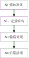
FIG. 1 is a flow diagram of an environmentally friendly meltblown fabric production process;
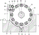
FIG. 2 is a schematic structural view of the present invention;
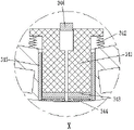
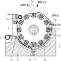
FIG. 3 is an overall cross-sectional view of the present invention;
FIG. 4 is an enlarged view of the X-direction portion of FIG. 3 of the present invention;
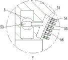
FIG. 5 is an enlarged view of the Y-direction portion of FIG. 3 of the present invention;
fig. 6 is a schematic view of the working state of the present invention.
Detailed Description
In order to make the technical means, the creation characteristics, the achievement purposes and the effects of the invention easy to understand, the invention is further explained below by combining the specific drawings. It should be noted that the embodiments and features of the embodiments in the present application may be combined with each other without conflict.
As shown in fig. 1 to 6, an environment-friendly meltblown fabric production process uses a cooling web-forming device, which includes a cooling base 1, a traction electric roller 2, a web-forming device 3, a mounting frame 4, an expanded region cleaning device 5 and a sticky device 6, and the meltblown fabric production process using the cooling web-forming device is as follows:
s1, melt preparation: putting the raw materials of the melt-blown cloth into a screw extruder for heating and melting to form a melt, and filtering impurities of the melt;
s2, quantitative discharge: quantitatively conveying the melt, spraying the melt in a spraying mode to form superfine fibers, gradually dripping the sprayed superfine fibers onto the rotary cylinder 31, gradually superposing the fallen superfine fibers to form reticular melt-blown cloth, and driving the rotary cylinder 31 to rotate at a low speed through the motor 32 so as to drive the melt-blown cloth to convey;
s3, conveying: when the meltblown fabric in the conveying state is conveyed to the position above the air cavity 12, cold air is blown out of the air cavity 12 through the air pump 13, so that the meltblown fabric is cooled, the cooled meltblown fabric is separated from the surface of the rotating cylinder 31 for conveying, the free end of the separated meltblown fabric is wound on the traction electric roller 2, and the meltblown fabric is driven to be stably conveyed through synchronous equidirectional rotation of the traction electric roller 2 and the rotating cylinder 31;
s4, later-stage cleaning: the rotary drum 31 separated from the meltblown fabric is subjected to air blowing and sticky cleaning by the expanded area cleaning device 5 and the sticky device 6, so that adhered impurities are removed.
Traction electric roller 2 is installed at the left end of cooling base 1, and the right-hand member of cooling base 1 is equipped with into net device 3, and the mid-mounting of cooling base 1 has installing frame 4, and the middle part of installing frame 4 is equipped with expands regional cleaning device 5, and the upper end of installing frame 4 is equipped with and is stained with and glues device 6.
The net forming device 3 comprises a rotating cylinder 31, a motor 32, a cooling cavity 33, an ejection mechanism 34, an inner cylinder 35, a second air pump 36 and two mounting plates 37, the two mounting plates 37 are arranged at the front end and the rear end of the mounting base 11, the two mounting plates 37 are connected with the rotating cylinder 31 through bearings, the front end of the rotating cylinder 31 is connected with an output shaft of the motor 32, the motor 32 is arranged on the mounting plate 37 at the front side, the cooling cavity 33 is uniformly arranged on the rotating cylinder 31 along the circumferential direction of the rotating cylinder, ice water is injected into the cooling cavity 33, certain cooling effect is achieved on the rotating cylinder 31, a movable cavity is uniformly arranged on the rotating cylinder 31 along the circumferential direction of the rotating cylinder, the movable cavity is provided with the ejection mechanism 34, the cooling cavity 33 and the movable cavity are arranged in a staggered mode, the inner cylinder 35 is arranged inside the rotating cylinder 31.
The ejection mechanism 34 include the movable block 341, reset spring 342, iron plate layer 343, two closing plates 344, sealed frame 345 and jam piece 346, the internally mounted of activity chamber has sealed frame 345, the inside cover of sealed frame 345 is equipped with movable block 341, even have reset spring 342 between the upper end of movable block 341 and the rotating cylinder 31 inner wall, the outer end of movable block 341 is equipped with iron plate layer 343, the activity chamber outer end is equipped with two closing plates 344, pass through hinged joint between the inner of closing plate 344 and the middle part of iron plate layer 343, rotating cylinder 31 internally mounted has jam piece 346.
During specific work, when the ejection mechanism 34 rotates to a position right above the electromagnet 14, the iron block layer 343 is sucked downwards through the magnetism of the electromagnet 14 in a working state, so that the movable block 341 is driven to descend synchronously, the two sealing plates 344 are driven to adjust the angle in opposite directions, the sealing plates 344 after angle adjustment are separated from the back of the melt-blown fabric, at the moment, the air blowing cavity is separated from the blocking blocks 346, cold air blown by the second air pump 36 can be sprayed out of the air blowing cavity, so that the separation from the melt-blown fabric is accelerated, the ejection mechanism 34 is driven to descend through the magnetic suction force, so that the melt-blown fabric is ejected downwards, the separation speed between the ejection mechanism 34 and the melt-blown fabric is accelerated through the contact area reduction and the air blowing mode, when the ejection mechanism 34 continues to rotate clockwise, the magnetic force gradually disappears, the movable block 341 gradually resets under the elasticity of the return spring 342, and the entire ejection.
The upper end right side of installation base 11 be indent formula arcwall face, and the left end of the indent formula arcwall face of installation base 11 is equipped with keeps apart fine hair, the meltblown fabric has separated with a rotary drum 31 when the left end of the indent formula arcwall face of installation base 11, the setting of keeping apart fine hair plays certain separation effect to between meltblown fabric and the installation base 11 indent formula arcwall face, has avoided meltblown fabric lower extreme terminal surface to lead to the condition that the gas ejection volume in air cavity 12 reduces after the indent formula arcwall face contacts.
The lower end of the inner barrel 35 is provided with a through hole, the second air pump 36 is connected with the through hole through a connecting pipe, and cold air is sprayed out of the through hole through the second air pump 36.
The outside of closing plate 344 be equipped with the pulley roller, and be connected for sliding fit between pulley roller and the activity chamber, guaranteed that iron plate layer 343 can drive closing plate 344 and carry out angle modulation when drawing close to the middle part when descending, be the laminating state between closing plate 344 lateral wall and the sealed frame 345 of initial position, improved sealed effect.
The middle part of the movable block 341 is provided with an air blowing cavity, the inner end of the air blowing cavity at the initial position is blocked with the blocking block 346, the movable block 341 is made of rubber, and the sealing effect between the movable block 341 and the air blowing cavity is improved due to the design of the rubber.
Expand regional cleaning device 5 include main cavity 51, No. three air pumps 53, trachea 54, gangbar 55 and flexible tube 56, main cavity 51 has been seted up at the middle part of installing frame 4, be the intercommunication relation between the left end of main cavity 51 and No. three air pumps 53, No. three air pumps 53 are installed in installing frame 4, the right-hand member of main cavity 51 evenly is equipped with and divides the chamber, divide and be connected through flexible tube 56 between chamber and the trachea 54, even there is gangbar 55 through the round pin axle between the trachea 54, concrete during operation, through No. three air pumps 53 with gaseous follow the blowout of flexible tube 56 behind trachea 54, because gaseous blowout has certain impact force, make the flexible tube 56 of not fixed connection carry out irregular swing, and drive flexible tube 56 through the effect of ganged bar 55 and carry out the coordinated type swing, thereby the scope of blowing has been increased, and then the clearance region has been enlarged.
The sticky device 6 comprises an inlet and outlet frame 61, a working spring 62, a working roller 63 and a sticky adhesive 64, the inlet and outlet frame 61 is connected with the upper end of the mounting frame 4 in a sliding fit manner, the working spring 62 is connected between the inlet and outlet frame 61 and the mounting frame 4, the working roller 63 is sleeved at the right end of the inlet and outlet frame 61, the sticky adhesive 64 is wound on the working roller 63, the surface adhesion cleaning is carried out on the passing rotating cylinder 31, the iron block layer 343 and the sealing plate 344 through the sticky adhesive 64, and the adhesion of the sticky adhesive 64 with the rotating cylinder 31, the iron block layer 343 and the sealing plate 344 is ensured by the elasticity of the working spring 62.
The foregoing illustrates and describes the principles, general features, and advantages of the present invention. It will be understood by those skilled in the art that the present invention is not limited to the embodiments described above, which are given by way of illustration of the principles of the present invention, and that various changes and modifications may be made without departing from the spirit and scope of the invention as defined by the appended claims. The scope of the invention is defined by the appended claims and equivalents thereof.
Claims (7)
1. The utility model provides an environmental protection melt-blown fabric production manufacturing process, its used a cooling and formed the equipment into the net, this cooling formed the equipment into the net includes cooling base (1), traction electric roller (2), becomes net device (3), installing frame (4), expands regional cleaning device (5) and is stained with and glues device (6), its characterized in that: the melt-blown fabric production process adopting the cooling net-forming equipment comprises the following steps:
s1, melt preparation: putting the raw materials of the melt-blown cloth into a screw extruder for heating and melting to form a melt, and filtering impurities of the melt;
s2, quantitative discharge: quantitatively conveying the melt, spraying the melt in a spraying mode to form superfine fibers, gradually dripping the sprayed superfine fibers onto a rotating cylinder (31), gradually superposing the fallen superfine fibers to form reticular melt-blown cloth, and driving the rotating cylinder (31) to rotate at a low speed through a motor (32) so as to drive the melt-blown cloth to be conveyed;
s3, conveying: when the melt-blown fabric in a conveying state is conveyed to the position above the air cavity (12), cold air is blown out of the air cavity (12) through the air pump (13), so that the melt-blown fabric is cooled, the cooled melt-blown fabric is separated from the surface of the rotating cylinder (31) for conveying, the free end of the separated melt-blown fabric is wound on the traction electric roller (2), and the melt-blown fabric is driven to be stably conveyed through synchronous equidirectional rotation of the traction electric roller (2) and the rotating cylinder (31);
s4, later-stage cleaning: the rotary drum (31) separated from the melt-blown cloth is subjected to air blowing and sticky cleaning through the expanded area cleaning device (5) and the sticky device (6), so that the adhered impurities are removed;
the left end of the cooling base (1) is provided with a traction electric roller (2), the right end of the cooling base (1) is provided with a net forming device (3), the middle part of the cooling base (1) is provided with an installation frame (4), the middle part of the installation frame (4) is provided with an expanded area cleaning device (5), and the upper end of the installation frame (4) is provided with a sticky device (6);
the cooling base (1) comprises a mounting base (11), an air cavity (12), an air pump (13), an electromagnet (14) and a turning roller (15), wherein the air cavity (12) is formed in the mounting base (11), the lower end of the air cavity (12) is connected with the air pump (13), the air pump (13) is mounted in the mounting base (11), the electromagnet (14) is mounted on the right side of the upper end of the mounting base (11), and the turning roller (15) is arranged in the middle of the upper end of the mounting base (11);
the net forming device (3) comprises a rotating cylinder (31), a motor (32), a cooling cavity (33), an ejection mechanism (34), an inner cylinder (35), a second air pump (36) and two mounting plates (37), wherein the two mounting plates (37) are arranged at the front end and the rear end of a mounting base (11), the two mounting plates (37) are connected with the rotating cylinder (31) through bearings, the front end of the rotating cylinder (31) is connected with an output shaft of the motor (32), the motor (32) is arranged on the mounting plate (37) at the front side, the cooling cavity (33) is uniformly arranged on the rotating cylinder (31) along the circumferential direction of the rotating cylinder, movable cavities are uniformly arranged on the rotating cylinder (31) along the circumferential direction of the rotating cylinder, the ejection mechanism (34) is arranged in the movable cavities, the cooling cavity (33) and the movable cavity are arranged in a staggered manner, an inner cylinder (35) is arranged in the rotating cylinder (31), and a second air pump (36) is arranged in the inner cylinder (35);
ejecting mechanism (34) including movable block (341), reset spring (342), iron plate layer (343), two closing plates (344), sealed frame (345) and jam piece (346), the internally mounted in activity chamber has sealed frame (345), the inside cover in sealed frame (345) is equipped with movable block (341), it has reset spring (342) to link between the upper end of movable block (341) and the inner wall of a rotating cylinder (31), the outer end of movable block (341) is equipped with iron plate layer (343), the activity chamber outer end is equipped with two closing plates (344), pass through hinged joint between the inner of closing plate (344) and the middle part of iron plate layer (343), rotating cylinder (31) internally mounted has jam piece (346).
2. The production and manufacturing process of the environment-friendly meltblown fabric according to claim 1, characterized by comprising the following steps: the right side of the upper end of the mounting base (11) is an inwards concave arc-shaped surface, and the left end of the inwards concave arc-shaped surface of the mounting base (11) is provided with isolation fluff.
3. The production and manufacturing process of the environment-friendly meltblown fabric according to claim 1, characterized by comprising the following steps: the lower end of the inner cylinder (35) is provided with a through hole, and the second air pump (36) is connected with the through hole through a connecting pipe.
4. The production and manufacturing process of the environment-friendly meltblown fabric according to claim 1, characterized by comprising the following steps: the outside of closing plate (344) be equipped with the pulley roller, and be sliding fit connection between pulley roller and the activity chamber, be the laminating state between closing plate (344) lateral wall and the sealing frame (345) of initial position.
5. The production and manufacturing process of the environment-friendly meltblown fabric according to claim 1, characterized by comprising the following steps: the middle part of the movable block (341) is provided with an air blowing cavity, a blocking state is formed between the inner end of the air blowing cavity at the initial position and the blocking block (346), and the movable block (341) is made of rubber.
6. The production and manufacturing process of the environment-friendly meltblown fabric according to claim 1, characterized by comprising the following steps: expand regional cleaning device (5) include main cavity (51), No. three air pump (53), trachea (54), gangbar (55) and flexible tube (56), main cavity (51) have been seted up at the middle part of installing frame (4), be the intercommunication relation between the left end of main cavity (51) and No. three air pump (53), install in installing frame (4) No. three air pump (53), the right-hand member of main cavity (51) evenly is equipped with the branch chamber, divide and be connected through flexible tube (56) between chamber and trachea (54), even have gangbar (55) through the round pin axle between trachea (54).
7. The production and manufacturing process of the environment-friendly meltblown fabric according to claim 1, characterized by comprising the following steps: be stained with and glue device (6) including business turn over frame (61), work spring (62), work roll (63) and be stained with and glue non-setting adhesive (64), business turn over frame (61) is connected for sliding fit with the upper end of installing frame (4), even have work spring (62) between business turn over frame (61) and installing frame (4), the right-hand member cover of business turn over frame (61) is equipped with work roll (63), the winding has to be stained with and glues non-setting adhesive (64) on work roll (63).
Priority Applications (1)
| Application Number | Priority Date | Filing Date | Title |
|---|---|---|---|
| CN202010569374.0A CN111663249B (en) | 2020-06-20 | 2020-06-20 | Production and manufacturing process of environment-friendly melt-blown fabric |
Applications Claiming Priority (1)
| Application Number | Priority Date | Filing Date | Title |
|---|---|---|---|
| CN202010569374.0A CN111663249B (en) | 2020-06-20 | 2020-06-20 | Production and manufacturing process of environment-friendly melt-blown fabric |
Publications (2)
| Publication Number | Publication Date |
|---|---|
| CN111663249A CN111663249A (en) | 2020-09-15 |
| CN111663249B true CN111663249B (en) | 2020-12-22 |
Family
ID=72389220
Family Applications (1)
| Application Number | Title | Priority Date | Filing Date |
|---|---|---|---|
| CN202010569374.0A Active CN111663249B (en) | 2020-06-20 | 2020-06-20 | Production and manufacturing process of environment-friendly melt-blown fabric |
Country Status (1)
| Country | Link |
|---|---|
| CN (1) | CN111663249B (en) |
Families Citing this family (5)
| Publication number | Priority date | Publication date | Assignee | Title |
|---|---|---|---|---|
| CN112170095A (en) * | 2020-09-27 | 2021-01-05 | 广州正益电子商务有限公司 | Braided material soaking device with automatic adjusting function |
| CN112522794A (en) * | 2020-12-14 | 2021-03-19 | 广西德福莱医疗器械有限公司 | Melt and spout cloth production line screw rod extrusion device |
| CN112695457A (en) * | 2020-12-18 | 2021-04-23 | 无锡艾度科技有限公司 | Cooling device and process for reducing melt-blown fabric resistance |
| CN113322582A (en) * | 2021-05-13 | 2021-08-31 | 贾鹏程 | Antibacterial melt-blown fabric production equipment |
| CN118685870A (en) * | 2024-07-12 | 2024-09-24 | 桐乡市健民过滤材料有限公司 | A melt-blowing machine die head rotating mechanism with adjustable width |
Family Cites Families (5)
| Publication number | Priority date | Publication date | Assignee | Title |
|---|---|---|---|---|
| DE19740338A1 (en) * | 1997-09-13 | 1999-03-18 | Truetzschler Gmbh & Co Kg | Device to form nonwovens |
| EP2532777A1 (en) * | 2011-05-19 | 2012-12-12 | Autoneum Management AG | Device for moulding fibrous material |
| CN204849359U (en) * | 2015-07-29 | 2015-12-09 | 无锡双象超纤材料股份有限公司 | Non -woven fabrics forming machine auxiliary coolant system |
| SI3575470T1 (en) * | 2018-05-28 | 2021-01-29 | Reifenhaeuser Gmbh & Co. Kg Maschinenfabrik | Device for the manufacture of woven material from continuous filaments |
| CN210458444U (en) * | 2019-08-30 | 2020-05-05 | 四川兴正源环保材料有限责任公司 | Melt-blown non-woven fabric web former |
-
2020
- 2020-06-20 CN CN202010569374.0A patent/CN111663249B/en active Active
Also Published As
| Publication number | Publication date |
|---|---|
| CN111663249A (en) | 2020-09-15 |
Similar Documents
| Publication | Publication Date | Title |
|---|---|---|
| CN111663249B (en) | Production and manufacturing process of environment-friendly melt-blown fabric | |
| CN110894671A (en) | A waste silk cleaning device for textile fabric processing | |
| CN114311703B (en) | Calendaring molding device for preparing anti-sticking air mold material | |
| CN115648605A (en) | Coating device and coating method for preparing refractory plate | |
| CN111663247A (en) | Non-woven fabric melt-blown processing method based on double-roller receiving device | |
| CN111426177B (en) | A vertical non-woven fabric processing device and non-woven fabric processing method | |
| CN101992162B (en) | Adhesive tape surface spraying machine | |
| CN114211645B (en) | An anti-adhesion filter glue device for producing automobile sealing strips | |
| CN116353182A (en) | A degradable environmentally friendly composite non-woven fabric preparation device and preparation process | |
| CN206884202U (en) | A kind of overlay film unit with sided corona treatment function | |
| CN220429272U (en) | Traction mechanism of film blowing machine | |
| CN112538741A (en) | Processing method of non-woven fabric honeycomb curtain fabric | |
| CN116476394B (en) | One-step forming production device for high molecular reaction self-adhesive waterproof coiled material film and use method | |
| CN106285058A (en) | Wind drenches pass-through box and dust free room | |
| CN114030112A (en) | High temperature resistant food package bag manufacturing installation | |
| CN211031570U (en) | Light antichemical clothes production is with rubber coating cloth heat seal device | |
| CN217556437U (en) | PP melts and spouts fibre netting equipment | |
| CN113684630A (en) | Asphalt waterproof coiled material preimpregnation device | |
| CN220364692U (en) | Melt-blown processing device for non-woven fabric production | |
| CN211488307U (en) | Wind supplementing device for powder spraying room separation chamber | |
| CN223795699U (en) | Drying and dedusting equipment for non-woven fabric production | |
| CN220538209U (en) | Fiber cloth winding device with material collecting mechanism | |
| CN216461178U (en) | Differential stretching mechanism with spray device | |
| CN220450565U (en) | Melt-blown cloth electrostatic device | |
| CN112976761A (en) | Compound filter media glueing set composite |
Legal Events
| Date | Code | Title | Description |
|---|---|---|---|
| PB01 | Publication | ||
| PB01 | Publication | ||
| SE01 | Entry into force of request for substantive examination | ||
| SE01 | Entry into force of request for substantive examination | ||
| TA01 | Transfer of patent application right | ||
| TA01 | Transfer of patent application right |
Effective date of registration: 20201203 Address after: No.377 Dongkang Road, Liushi street, Dongyang City, Jinhua City, Zhejiang Province Applicant after: Dongyang Aolong New Material Technology Co., Ltd Address before: No.19 Xinwu group, Yijin village, Yijin Town, Zongyang County, Anqing City, Anhui Province 246700 Applicant before: Zhang Yuying |
|
| GR01 | Patent grant | ||
| GR01 | Patent grant |