CN111663103A - Evaporation plating device - Google Patents
Evaporation plating device Download PDFInfo
- Publication number
- CN111663103A CN111663103A CN202010531723.XA CN202010531723A CN111663103A CN 111663103 A CN111663103 A CN 111663103A CN 202010531723 A CN202010531723 A CN 202010531723A CN 111663103 A CN111663103 A CN 111663103A
- Authority
- CN
- China
- Prior art keywords
- nozzle
- height
- plate
- evaporation source
- source body
- Prior art date
- Legal status (The legal status is an assumption and is not a legal conclusion. Google has not performed a legal analysis and makes no representation as to the accuracy of the status listed.)
- Granted
Links
Images


Classifications
-
- C—CHEMISTRY; METALLURGY
- C23—COATING METALLIC MATERIAL; COATING MATERIAL WITH METALLIC MATERIAL; CHEMICAL SURFACE TREATMENT; DIFFUSION TREATMENT OF METALLIC MATERIAL; COATING BY VACUUM EVAPORATION, BY SPUTTERING, BY ION IMPLANTATION OR BY CHEMICAL VAPOUR DEPOSITION, IN GENERAL; INHIBITING CORROSION OF METALLIC MATERIAL OR INCRUSTATION IN GENERAL
- C23C—COATING METALLIC MATERIAL; COATING MATERIAL WITH METALLIC MATERIAL; SURFACE TREATMENT OF METALLIC MATERIAL BY DIFFUSION INTO THE SURFACE, BY CHEMICAL CONVERSION OR SUBSTITUTION; COATING BY VACUUM EVAPORATION, BY SPUTTERING, BY ION IMPLANTATION OR BY CHEMICAL VAPOUR DEPOSITION, IN GENERAL
- C23C14/00—Coating by vacuum evaporation, by sputtering or by ion implantation of the coating forming material
- C23C14/22—Coating by vacuum evaporation, by sputtering or by ion implantation of the coating forming material characterised by the process of coating
- C23C14/24—Vacuum evaporation
-
- C—CHEMISTRY; METALLURGY
- C23—COATING METALLIC MATERIAL; COATING MATERIAL WITH METALLIC MATERIAL; CHEMICAL SURFACE TREATMENT; DIFFUSION TREATMENT OF METALLIC MATERIAL; COATING BY VACUUM EVAPORATION, BY SPUTTERING, BY ION IMPLANTATION OR BY CHEMICAL VAPOUR DEPOSITION, IN GENERAL; INHIBITING CORROSION OF METALLIC MATERIAL OR INCRUSTATION IN GENERAL
- C23C—COATING METALLIC MATERIAL; COATING MATERIAL WITH METALLIC MATERIAL; SURFACE TREATMENT OF METALLIC MATERIAL BY DIFFUSION INTO THE SURFACE, BY CHEMICAL CONVERSION OR SUBSTITUTION; COATING BY VACUUM EVAPORATION, BY SPUTTERING, BY ION IMPLANTATION OR BY CHEMICAL VAPOUR DEPOSITION, IN GENERAL
- C23C14/00—Coating by vacuum evaporation, by sputtering or by ion implantation of the coating forming material
- C23C14/22—Coating by vacuum evaporation, by sputtering or by ion implantation of the coating forming material characterised by the process of coating
- C23C14/54—Controlling or regulating the coating process
- C23C14/542—Controlling the film thickness or evaporation rate
Landscapes
- Chemical & Material Sciences (AREA)
- Chemical Kinetics & Catalysis (AREA)
- Engineering & Computer Science (AREA)
- Materials Engineering (AREA)
- Mechanical Engineering (AREA)
- Metallurgy (AREA)
- Organic Chemistry (AREA)
- Physical Vapour Deposition (AREA)
Abstract
本发明涉及蒸镀技术领域,公开一种蒸镀装置,其包括:蒸发源组件,包括蒸发源本体、第一喷嘴和第二喷嘴,第二喷嘴位于第一喷嘴的外侧,第一喷嘴的第一半径r1小于第二喷嘴的第二半径r2;限制板,限制板的个数为两个,两个限制板沿蒸发源本体宽度方向分别设于蒸发源本体的两侧且面对面设置,限制板正对第一喷嘴的部位高出第一喷嘴的高度为第一高度,限制板正对第二喷嘴的部位高出第二喷嘴的高度为第二高度,第一高度小于第二高度。本发明公开的蒸镀结构通过增高半径较大的第二喷嘴正对的限制板的高度,在不改变膜层沿蒸发源本体长度方向的厚度的前提下,从而使位于基板上的膜层沿限制板的宽度方向的厚度降低,即提高了膜层的整体均匀性。

The invention relates to the technical field of evaporation, and discloses an evaporation device, comprising: an evaporation source assembly, including an evaporation source body, a first nozzle and a second nozzle, the second nozzle is located outside the first nozzle, and the first nozzle is located on the outside of the first nozzle. A radius r1 is smaller than the second radius r2 of the second nozzle; the restriction plate, the number of the restriction plate is two, the two restriction plates are respectively arranged on both sides of the evaporation source body along the width direction of the evaporation source body and are arranged face to face, the restriction plate The height of the part facing the first nozzle higher than the first nozzle is the first height, the height of the part facing the second nozzle higher than the second nozzle is the second height, and the first height is smaller than the second height. The evaporation structure disclosed in the present invention increases the height of the limiting plate facing the second nozzle with a larger radius, without changing the thickness of the film along the length of the evaporation source body, so that the film on the substrate can be The thickness of the limiting plate in the width direction is reduced, that is, the overall uniformity of the film layer is improved.
Description
技术领域technical field
本发明涉及蒸镀技术领域,尤其涉及一种蒸镀装置。The present invention relates to the technical field of evaporation, and in particular, to an evaporation device.
背景技术Background technique
真空蒸镀技术是依靠蒸镀装置在基板上进行镀膜的技术,它是OLED生产工艺中的核心技术。现有的蒸镀装置一般设置有两个限制板和两种半径的多个喷嘴,限制板是根据需求一次性设计做成的挡板,高度相同,位于端部的喷嘴的半径较大,位于中间的喷嘴的半径较小,这种设置虽然增加膜层沿蒸发源本体长度方向的均匀性,但是由于限制板的高度相同,使得半径较大的喷嘴在沿限制板的厚度方向的膜厚增加,即降低了膜层沿蒸发源本体宽度方向的均匀性。Vacuum evaporation technology is a technology that relies on an evaporation device to coat a substrate, and it is the core technology in the OLED production process. Existing evaporation devices are generally provided with two restricting plates and multiple nozzles with two radii. The restricting plates are baffles designed and made at one time according to requirements, with the same height. The nozzle in the middle has a smaller radius. Although this arrangement increases the uniformity of the film along the length of the evaporation source body, because the height of the limiting plate is the same, the film thickness of the nozzle with a larger radius increases along the thickness of the limiting plate. , that is, the uniformity of the film layer along the width direction of the evaporation source body is reduced.
发明内容SUMMARY OF THE INVENTION
基于以上所述,本发明的目的在于提供一种蒸镀装置,增加了膜层沿蒸发源本体宽度方向的均匀性。Based on the above, the purpose of the present invention is to provide an evaporation device, which increases the uniformity of the film layer along the width direction of the evaporation source body.
为达上述目的,本发明采用以下技术方案:For achieving the above object, the present invention adopts the following technical solutions:
一种蒸镀装置,包括:蒸发源组件,所述蒸发源组件包括蒸发源本体、第一喷嘴和第二喷嘴,所述第一喷嘴和所述第二喷嘴分别与所述蒸发源本体连通,所述第二喷嘴位于所述第一喷嘴的外侧,所述第一喷嘴的第一半径r1小于所述第二喷嘴的第二半径r2;限制板,所述限制板的个数为两个,两个所述限制板沿所述蒸发源本体宽度方向分别设于所述蒸发源本体的两侧且面对面设置,所述限制板正对所述第一喷嘴的部位高出所述第一喷嘴的高度为第一高度,所述限制板正对所述第二喷嘴的部位高出所述第二喷嘴的高度为第二高度,所述第一高度小于所述第二高度。An evaporation device, comprising: an evaporation source assembly, the evaporation source assembly includes an evaporation source body, a first nozzle and a second nozzle, the first nozzle and the second nozzle are respectively communicated with the evaporation source body, The second nozzle is located outside the first nozzle, and the first radius r1 of the first nozzle is smaller than the second radius r2 of the second nozzle; limiting plates, the number of the limiting plates is two, The two restricting plates are respectively arranged on both sides of the evaporation source body along the width direction of the evaporation source body and are arranged facing each other, and the portion of the restricting plate facing the first nozzle is higher than the first nozzle. The height is the first height, the height of the portion of the restricting plate facing the second nozzle higher than the second nozzle is the second height, and the first height is smaller than the second height.
作为一种蒸镀结构的优选方案,所述蒸镀装置用于向基板蒸镀膜层;所述第一喷嘴的出口端与所述基板的距离为D,所述第一高度为Z1,所述第二高度与所述第一高度的差值为Z2,r2与r1的差值为X1,所述第二喷嘴靠近所述限制板的一端至所述限制板的最小距离为X2,所述限制板在所述基板上沿所述蒸发源本体宽度方向的投影至所述基板的第一位置的距离为X3,X1、X2、X3、D、Z1及Z2满足关系式:Z2=(X1+X2)×D/(X1+X2+X3)-Z1,其中,X3=(D/Z1-1)×X2。As a preferred solution of the evaporation structure, the evaporation device is used to evaporate a film layer on the substrate; the distance between the outlet end of the first nozzle and the substrate is D, the first height is Z1, the The difference between the second height and the first height is Z2, the difference between r2 and r1 is X1, and the minimum distance from the end of the second nozzle close to the restriction plate to the restriction plate is X2, and the restriction The distance from the projection of the plate on the substrate to the first position of the substrate along the width direction of the evaporation source body is X3, and X1, X2, X3, D, Z1 and Z2 satisfy the relationship: Z2=(X1+X2 )×D/(X1+X2+X3)−Z1, where X3=(D/Z1−1)×X2.
作为一种蒸镀结构的优选方案,所述第二喷嘴的个数为两个,每个所述限制板包括第一限制板和间隔设于所述第一限制板上的两个第二限制板,每个所述第二限制板正对一个所述第二喷嘴设置。As a preferred solution of the evaporation structure, the number of the second nozzles is two, and each of the restricting plates includes a first restricting plate and two second restricting plates arranged at intervals on the first restricting plate Plates, each of the second restricting plates is disposed opposite to one of the second nozzles.
作为一种蒸镀结构的优选方案,所述第二限制板为等腰梯形板,所述等腰梯形板的下底抵接于所述第一限制板,所述第二喷嘴的中心轴线与所述等腰梯形板的对称轴沿所述蒸发源本体宽度方向设置。As a preferred solution of the vapor deposition structure, the second restricting plate is an isosceles trapezoid plate, the lower bottom of the isosceles trapezoidal plate abuts the first restricting plate, and the center axis of the second nozzle is in contact with the first restricting plate. The symmetry axis of the isosceles trapezoid plate is arranged along the width direction of the evaporation source body.
作为一种蒸镀结构的优选方案,所述第二喷嘴的中心至与其相邻的所述第一喷嘴的中心的距离为a,所述等腰梯形板的腰在所述蒸发源本体上的投影的长度为f,所述等腰梯形板的上底的长度为C,r1、r2、Z1、D、a、f、C满足关系式,f=α×2×(r2-r1)×Z1/D,C=2×(a-f)×r2/(r1+r2),其中,α为修正系数。As a preferred solution of the evaporation structure, the distance from the center of the second nozzle to the center of the adjacent first nozzle is a, and the waist of the isosceles trapezoid plate is on the evaporation source body. The length of the projection is f, the length of the upper base of the isosceles trapezoid plate is C, r1, r2, Z1, D, a, f, and C satisfy the relational expression, f=α×2×(r2-r1)×Z1 /D, C=2×(a-f)×r2/(r1+r2), where α is a correction coefficient.
作为一种蒸镀结构的优选方案,α位于0.5-10之间,其中,α与D和a成反比,且α与r1和r2成正比。As a preferred solution of the vapor deposition structure, α is between 0.5-10, wherein α is inversely proportional to D and a, and α is proportional to r1 and r2.
作为一种蒸镀结构的优选方案,所述第一限制板和所述第二限制板为一体成型结构。As a preferred solution of the vapor deposition structure, the first confinement plate and the second confinement plate are integrally formed.
作为一种蒸镀结构的优选方案,所述第二限制板为长方形板或弧形板,所述弧形板靠近所述第一限制板的侧边为第一直边,所述弧形板正对所述第一直边的侧边为第二直边,所述第一直边的长度大于所述第二直边的长度且所述第一直边与所述第二直边通过圆弧连接。As a preferred solution of the evaporation structure, the second restricting plate is a rectangular plate or an arc-shaped plate, the side of the arc-shaped plate close to the first restricting plate is a first straight edge, and the arc-shaped plate is a first straight edge. The side facing the first straight edge is a second straight edge, the length of the first straight edge is greater than the length of the second straight edge, and the first straight edge and the second straight edge pass through a circle arc connection.
作为一种蒸镀结构的优选方案,所述第一喷嘴的个数为至少两个,一个所述第二喷嘴、所述第一喷嘴及另一个所述第二喷嘴沿所述蒸发源本体长度方向依次间隔排布。As a preferred solution of the evaporation structure, the number of the first nozzles is at least two, and one of the second nozzles, the first nozzle and the other of the second nozzles are along the length of the evaporation source body The directions are spaced in sequence.
作为一种蒸镀结构的优选方案,所述第一喷嘴的出口端面与所述第二喷嘴的出口端面平齐。As a preferred solution of the vapor deposition structure, the outlet end face of the first nozzle is flush with the outlet end face of the second nozzle.
本发明的有益效果为:本发明公开的蒸镀结构通过增高半径较大的第二喷嘴正对的限制板的高度,在不改变膜层沿蒸发源本体长度方向的厚度的前提下,从而使位于基板上的膜层沿限制板的宽度方向的厚度降低,即提高了膜层的整体均匀性。The beneficial effects of the present invention are as follows: the evaporation structure disclosed in the present invention increases the height of the restriction plate facing the second nozzle with a larger radius, without changing the thickness of the film along the length direction of the evaporation source body, so that the The thickness of the film layer on the substrate along the width direction of the limiting plate is reduced, that is, the overall uniformity of the film layer is improved.
附图说明Description of drawings
为了更清楚地说明本发明实施例中的技术方案,下面将对本发明实施例描述中所需要使用的附图作简单的介绍,显而易见地,下面描述中的附图仅仅是本发明的一些实施例,对于本领域普通技术人员来讲,在不付出创造性劳动的前提下,还可以根据本发明实施例的内容和这些附图获得其他的附图。In order to illustrate the technical solutions in the embodiments of the present invention more clearly, the following briefly introduces the accompanying drawings that need to be used in the description of the embodiments of the present invention. Obviously, the drawings in the following description are only some embodiments of the present invention. , for those of ordinary skill in the art, other drawings can also be obtained according to the contents of the embodiments of the present invention and these drawings without creative efforts.
图1是本发明具体实施例提供的蒸镀结构的示意图;1 is a schematic diagram of an evaporation structure provided by a specific embodiment of the present invention;
图2是本发明具体实施例提供的第一喷嘴和第二喷嘴与基板的相对位置的简易示意图;2 is a simplified schematic diagram of the relative positions of the first nozzle and the second nozzle and the substrate provided by a specific embodiment of the present invention;
图3是本发明具体实施例提供的限制板的示意图;3 is a schematic diagram of a restriction plate provided by a specific embodiment of the present invention;
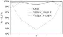
图4是现有技术和本发明在匹配区域和不匹配区域在Y轴方向的膜层的归一化厚度的曲线图;4 is a graph of the normalized thickness of the film layers in the Y-axis direction in the matched region and the unmatched region of the prior art and the present invention;
图5是基于本发明的蒸镀结构采用软件模拟和实际测量得到的在Y轴方向的膜层的归一化厚度的对比曲线图。FIG. 5 is a comparison graph of the normalized thickness of the film layer in the Y-axis direction obtained by software simulation and actual measurement based on the vapor deposition structure of the present invention.
图中:In the picture:
1、蒸发源本体;1. Evaporation source body;
21、第一喷嘴;22、第二喷嘴;21. The first nozzle; 22. The second nozzle;
3、限制板;31、第一限制板;32、第二限制板;3. Limiting plate; 31. First limiting plate; 32. Second limiting plate;
4、基板。4. Substrate.
具体实施方式Detailed ways
为使本发明解决的技术问题、采用的技术方案和达到的技术效果更加清楚,下面将结合附图对本发明实施例的技术方案作进一步的详细描述,显然,所描述的实施例仅仅是本发明一部分实施例,而不是全部的实施例。基于本发明中的实施例,本领域技术人员在没有作出创造性劳动前提下所获得的所有其他实施例,都属于本发明保护的范围。In order to make the technical problems solved by the present invention, the technical solutions adopted and the technical effects achieved more clearly, the technical solutions of the embodiments of the present invention will be described in further detail below with reference to the accompanying drawings. Obviously, the described embodiments are only the present invention. Some examples, but not all examples. Based on the embodiments of the present invention, all other embodiments obtained by those skilled in the art without creative efforts shall fall within the protection scope of the present invention.
在本发明的描述中,需要说明的是,术语“中心”、“上”、“下”、“左”、“右”、“竖直”、“水平”、“内”、“外”等指示的方位或位置关系为基于附图所示的方位或位置关系,仅是为了便于描述本发明和简化描述,而不是指示或暗示所指的装置或元件必须具有特定的方位、以特定的方位构造和操作,因此不能理解为对本发明的限制。此外,术语“第一”、“第二”仅用于描述目的,而不能理解为指示或暗示相对重要性。其中,术语“第一位置”和“第二位置”为两个不同的位置。In the description of the present invention, it should be noted that the terms "center", "upper", "lower", "left", "right", "vertical", "horizontal", "inner", "outer", etc. The indicated orientation or positional relationship is based on the orientation or positional relationship shown in the accompanying drawings, which is only for the convenience of describing the present invention and simplifying the description, rather than indicating or implying that the indicated device or element must have a specific orientation or a specific orientation. construction and operation, and therefore should not be construed as limiting the invention. Furthermore, the terms "first" and "second" are used for descriptive purposes only and should not be construed to indicate or imply relative importance. Therein, the terms "first position" and "second position" are two different positions.
在本发明的描述中,需要说明的是,除非另有明确的规定和限定,术语“安装”、“相连”、“连接”应做广义理解,例如,可以是固定连接,也可以是可拆卸连接;可以是机械连接,也可以是电连接;可以是直接相连,也可以通过中间媒介间接相连,可以是两个元件内部的连通。对于本领域的普通技术人员而言,可以具体情况理解上述术语在本发明中的具体含义。In the description of the present invention, it should be noted that the terms "installed", "connected" and "connected" should be understood in a broad sense, unless otherwise expressly specified and limited, for example, it may be a fixed connection or a detachable connection Connection; it can be a mechanical connection or an electrical connection; it can be a direct connection or an indirect connection through an intermediate medium, and it can be the internal communication of two components. For those of ordinary skill in the art, the specific meanings of the above terms in the present invention can be understood in specific situations.
本实施例提供一种蒸镀装置,如图1至图3所示,该蒸镀装置用于向基板4蒸镀膜层,蒸镀装置包括蒸发源组件和限制板3,蒸发源组件包括蒸发源本体1、第一喷嘴21和第二喷嘴22,第一喷嘴21和第二喷嘴22分别与蒸发源本体1连通,第二喷嘴22位于第一喷嘴21的外侧,第一喷嘴21的出口端面与第二喷嘴22的出口端面平齐。第一喷嘴21的第一半径r1小于第二喷嘴22的第二半径r2,限制板3的个数为两个,两个限制板3沿蒸发源本体1宽度方向分别设于蒸发源本体1的两侧且面对面设置,限制板3正对第一喷嘴21的部位高出第一喷嘴21的高度为第一高度,限制板3正对第二喷嘴22的部位高出第二喷嘴22的高度为第二高度,第一高度小于第二高度。This embodiment provides an evaporation device, as shown in FIG. 1 to FIG. 3 , the evaporation device is used for evaporating a film layer on the
如图1所示,本实施例的第一喷嘴21的个数为两个,第二喷嘴22的个数为两个,一个第二喷嘴22、两个第一喷嘴21及另一个第二喷嘴22沿蒸发源本体1长度方向依次间隔排布。当然,在本发明的其他实施例中,第一喷嘴21的个数还可以为一个或者多于两个,第一喷嘴21的个数具体根据实际需要设置。As shown in FIG. 1 , the number of the
本实施例提供的蒸镀结构通过增高半径较大的第二喷嘴22正对的限制板3的高度,在不改变膜层沿蒸发源本体1长度方向的厚度的前提下,从而使位于基板4上的膜层沿限制板3的宽度方向的厚度降低,即提高了膜层的整体均匀性。The evaporation structure provided in this embodiment increases the height of the limiting
具体地,如图2所示,本实施例的第一喷嘴21的出口端与基板4的距离为D,第一高度为Z1,第二高度与第一高度的差值为Z2,r2与r1的差值为X1,第二喷嘴22靠近限制板3的一端至限制板3的最小距离为X2,限制板3在基板4上沿蒸发源本体1宽度方向的投影至基板4的第一位置的距离为X3,X1、X2、X3、D、Z1及Z2满足关系式:Z2=(X1+X2)×D/(X1+X2+X3)-Z1,其中,X3=(D/Z1-1)×X2。Specifically, as shown in FIG. 2 , in this embodiment, the distance between the outlet end of the
需要说明的是,如图2所示,假设第一喷嘴21的中心和第二喷嘴22的中心重合,根据第一喷嘴21和第二喷嘴22在基板4上形成的膜层的厚度的均匀性,将基板4分为匹配区域和不匹配区域,其中匹配区域在X轴方向的长度为2×(r2+X2+X3),不匹配区域在X轴方向的长度为2L,第一位置位于匹配区域和不匹配区域的交汇处。It should be noted that, as shown in FIG. 2 , assuming that the center of the
具体地,以蒸发源本体1的宽度方向为X轴、以蒸发源本体1的长度方向为Y轴、以限制板3的高度方向为Z轴建立坐标系,在现有技术中,利用软件进行模拟,由模拟结果知,在基板4的匹配区域沿任一与Y轴平行的方向,基板4的匹配区域的膜层的归一化厚度与Y轴的位置关系如图4所示,匹配区域的均一性较好,约为96%,基板4的不匹配区域与Y轴的位置关系如图4所示,由图4可知,匹配区域的均一性较差,约为74%,由此可知,在改善前基板4的不匹配区域的均一性较差。Specifically, a coordinate system is established with the width direction of the
如图1和图3所示,本实施例的每个限制板3包括第一限制板31和间隔设于第一限制板31上的两个第二限制板32,每个第二限制板32正对一个第二喷嘴22设置。具体地,本实施例的第二限制板32为等腰梯形板,等腰梯形板的下底抵接于第一限制板31,第二喷嘴22的中心轴线与等腰梯形板的对称轴沿蒸发源本体1宽度方向设置。As shown in FIG. 1 and FIG. 3 , each restricting
如图3所示,本实施例的第二喷嘴22的中心至与其相邻的第一喷嘴21的中心的距离为a,相邻两个第一喷嘴21的中心之间的距离为b,等腰梯形板的下底在蒸发源本体1上的投影靠近第一喷嘴21的一端至与其相邻的第一喷嘴21的中心在蒸发源本体1的长度方向的距离为g,等腰梯形板的腰在蒸发源本体1上的投影的长度为f,等腰梯形板的上底的长度为C,r1、r2、Z1、D、a、b、f、g、C满足关系式,f=α×2×X1×Z1/D,C=2×(a-f)×r2/(r1+r2),g=(a-f)×r1/(r1+r2),其中,α为修正系数。具体地,α位于0.5-10之间,其中,α与D和a成反比,且α与r1和r2成正比。As shown in FIG. 3 , the distance from the center of the
采用本实施例的限制板3后重新用软件进行模拟,在基板4的匹配区域沿任一与Y轴平行的方向,现有技术的不匹配区域与Y轴的位置关系如图4所示,由图4可知,现有技术的不匹配区域采用本实施例的蒸镀结构后其膜层的厚度较为均匀,约为94%,由此可知,采用本实施例的蒸镀结构提高了改善前不匹配区域的膜层的均一性,使得膜层的厚度较为均匀。After using the limiting
为了验证软件模拟结果的准确性,采用与模拟中的相同参数的蒸镀结构对基板4进行镀膜,如图5所示,根据实验结果知,实验得到的膜层的归一化厚度与软件模拟得到的归一化厚度的误差小于0.5%,这表明本实施例的蒸镀结构能够增加改善前不匹配区域的膜层的均匀性,整个基板4的整体膜层厚度趋于一致。In order to verify the accuracy of the software simulation results, the
本实施例的第一限制板31和第二限制板32为一体成型结构。当然,在其他实施例中,还可以是将两个第二限制板32固定安装在第一限制板31上,从而形成一个限制板3,限制板3的具体形式根据实际需要设置。在本发明的其他实施例中,第二限制板32的结构并不限于本实施例的等腰梯形板,还可以是第二限制板32为长方形板或弧形板,弧形板靠近第一限制板31的侧边为第一直边,弧形板正对第一直边的侧边为第二直边,第一直边的长度大于第二直边的长度且第一直边与第二直边通过圆弧连接。The first restricting
注意,上述仅为本发明的较佳实施例及所运用技术原理。本领域技术人员会理解,本发明不限于这里所述的特定实施例,对本领域技术人员来说能够进行各种明显的变化、重新调整和替代而不会脱离本发明的保护范围。因此,虽然通过以上实施例对本发明进行了较为详细的说明,但是本发明不仅仅限于以上实施例,在不脱离本发明构思的情况下,还可以包括更多其他等效实施例,而本发明的范围由所附的权利要求范围决定。Note that the above are only preferred embodiments of the present invention and applied technical principles. Those skilled in the art will understand that the present invention is not limited to the specific embodiments described herein, and various obvious changes, readjustments and substitutions can be made by those skilled in the art without departing from the protection scope of the present invention. Therefore, although the present invention has been described in detail through the above embodiments, the present invention is not limited to the above embodiments, and can also include more other equivalent embodiments without departing from the concept of the present invention. The scope is determined by the scope of the appended claims.
Claims (10)
Priority Applications (1)
| Application Number | Priority Date | Filing Date | Title |
|---|---|---|---|
| CN202010531723.XA CN111663103B (en) | 2020-06-11 | 2020-06-11 | Evaporation plating device |
Applications Claiming Priority (1)
| Application Number | Priority Date | Filing Date | Title |
|---|---|---|---|
| CN202010531723.XA CN111663103B (en) | 2020-06-11 | 2020-06-11 | Evaporation plating device |
Publications (2)
| Publication Number | Publication Date |
|---|---|
| CN111663103A true CN111663103A (en) | 2020-09-15 |
| CN111663103B CN111663103B (en) | 2022-10-21 |
Family
ID=72386856
Family Applications (1)
| Application Number | Title | Priority Date | Filing Date |
|---|---|---|---|
| CN202010531723.XA Active CN111663103B (en) | 2020-06-11 | 2020-06-11 | Evaporation plating device |
Country Status (1)
| Country | Link |
|---|---|
| CN (1) | CN111663103B (en) |
Citations (6)
| Publication number | Priority date | Publication date | Assignee | Title |
|---|---|---|---|---|
| US20120064663A1 (en) * | 2010-09-15 | 2012-03-15 | Seung-Ho Choi | Device and method for depositing organic material |
| US20160214133A1 (en) * | 2015-01-22 | 2016-07-28 | Samsung Display Co., Ltd. | Deposition source including plurality of modules |
| CN106958007A (en) * | 2017-05-12 | 2017-07-18 | 武汉华星光电技术有限公司 | Vaporising device |
| CN207418851U (en) * | 2017-09-22 | 2018-05-29 | 云谷(固安)科技有限公司 | Evaporation source |
| CN208250403U (en) * | 2018-03-30 | 2018-12-18 | 昆山国显光电有限公司 | Evaporation coating device |
| CN110578121A (en) * | 2019-10-08 | 2019-12-17 | 京东方科技集团股份有限公司 | Evaporation equipment |
-
2020
- 2020-06-11 CN CN202010531723.XA patent/CN111663103B/en active Active
Patent Citations (7)
| Publication number | Priority date | Publication date | Assignee | Title |
|---|---|---|---|---|
| US20120064663A1 (en) * | 2010-09-15 | 2012-03-15 | Seung-Ho Choi | Device and method for depositing organic material |
| KR20120028628A (en) * | 2010-09-15 | 2012-03-23 | 삼성모바일디스플레이주식회사 | Apparatus for depositing organic material and method for depositing thereof |
| US20160214133A1 (en) * | 2015-01-22 | 2016-07-28 | Samsung Display Co., Ltd. | Deposition source including plurality of modules |
| CN106958007A (en) * | 2017-05-12 | 2017-07-18 | 武汉华星光电技术有限公司 | Vaporising device |
| CN207418851U (en) * | 2017-09-22 | 2018-05-29 | 云谷(固安)科技有限公司 | Evaporation source |
| CN208250403U (en) * | 2018-03-30 | 2018-12-18 | 昆山国显光电有限公司 | Evaporation coating device |
| CN110578121A (en) * | 2019-10-08 | 2019-12-17 | 京东方科技集团股份有限公司 | Evaporation equipment |
Also Published As
| Publication number | Publication date |
|---|---|
| CN111663103B (en) | 2022-10-21 |
Similar Documents
| Publication | Publication Date | Title |
|---|---|---|
| CN108004503B (en) | Mask plate, evaporation equipment and device | |
| CN105143497B (en) | Evaporation mask, vapor deposition mask preparation, method of manufacturing vapor deposition mask, and method of manufacturing organic semiconductor element | |
| CN112739845B (en) | Mask plate and preparation method, fine metal mask plate, mask device and use method | |
| WO2021027922A1 (en) | Touch control substrate, touch control display panel and touch control display apparatus | |
| JP2014077193A (en) | Vapor deposition apparatus and organic light-emitting display device manufacturing method using the same | |
| CN210926019U (en) | Display backplane, reticle assembly and display device | |
| CN117794276B (en) | Display panel and preparation method thereof | |
| JP2025013942A (en) | Metal substrate and deposition mask using same | |
| CN111663103B (en) | Evaporation plating device | |
| WO2020233487A1 (en) | Pixel structure, display substrate, mask and evaporation method | |
| CN109328244A (en) | Vacuum Evaporation Device | |
| WO2020143115A1 (en) | Display panel | |
| WO2024125354A1 (en) | Spray plate, spray method, and processing device | |
| CN106033802A (en) | A mask for evaporation and its manufacturing method | |
| US12077870B2 (en) | Mask manufacturing method and mask manufacturing device | |
| US11560616B2 (en) | Mask device, mask plate, and frame | |
| CN211265631U (en) | Electric pile end plate and electric pile structure | |
| CN119838821B (en) | Detachable slit coating die head and coating equipment | |
| CN108677148B (en) | Vapor deposition source, vapor deposition device | |
| CN110777328A (en) | A kind of mask plate, evaporation system and preparation method of mask plate | |
| CN109950282A (en) | Dot structure, array substrate and display device | |
| CN102480056A (en) | Base station antenna | |
| CN221797658U (en) | Processing platform and coating equipment | |
| CN212247181U (en) | Evaporation plating device | |
| CN111254387A (en) | Mask assembly and process method thereof, and process method for producing functional film layer |
Legal Events
| Date | Code | Title | Description |
|---|---|---|---|
| PB01 | Publication | ||
| PB01 | Publication | ||
| SE01 | Entry into force of request for substantive examination | ||
| SE01 | Entry into force of request for substantive examination | ||
| GR01 | Patent grant | ||
| GR01 | Patent grant | ||
| PE01 | Entry into force of the registration of the contract for pledge of patent right | ||
| PE01 | Entry into force of the registration of the contract for pledge of patent right |
Denomination of invention: A vapor plating device Effective date of registration: 20231225 Granted publication date: 20221021 Pledgee: Industrial Bank Limited by Share Ltd. Hefei branch Pledgor: HEFEI SHIYA DISPLAY TECHNOLOGY Co.,Ltd. Registration number: Y2023980073942 |
|
| PC01 | Cancellation of the registration of the contract for pledge of patent right | ||
| PC01 | Cancellation of the registration of the contract for pledge of patent right |
Granted publication date: 20221021 Pledgee: Industrial Bank Limited by Share Ltd. Hefei branch Pledgor: HEFEI SHIYA DISPLAY TECHNOLOGY Co.,Ltd. Registration number: Y2023980073942 |