CN111642363A - Spherical plant irrigator - Google Patents
Spherical plant irrigator Download PDFInfo
- Publication number
- CN111642363A CN111642363A CN202010561623.1A CN202010561623A CN111642363A CN 111642363 A CN111642363 A CN 111642363A CN 202010561623 A CN202010561623 A CN 202010561623A CN 111642363 A CN111642363 A CN 111642363A
- Authority
- CN
- China
- Prior art keywords
- water flow
- turbine
- driving mechanism
- shell
- annular
- Prior art date
- Legal status (The legal status is an assumption and is not a legal conclusion. Google has not performed a legal analysis and makes no representation as to the accuracy of the status listed.)
- Granted
Links
Images


Classifications
-
- A—HUMAN NECESSITIES
- A01—AGRICULTURE; FORESTRY; ANIMAL HUSBANDRY; HUNTING; TRAPPING; FISHING
- A01G—HORTICULTURE; CULTIVATION OF VEGETABLES, FLOWERS, RICE, FRUIT, VINES, HOPS OR SEAWEED; FORESTRY; WATERING
- A01G25/00—Watering gardens, fields, sports grounds or the like
- A01G25/02—Watering arrangements located above the soil which make use of perforated pipe-lines or pipe-lines with dispensing fittings, e.g. for drip irrigation
-
- A—HUMAN NECESSITIES
- A01—AGRICULTURE; FORESTRY; ANIMAL HUSBANDRY; HUNTING; TRAPPING; FISHING
- A01G—HORTICULTURE; CULTIVATION OF VEGETABLES, FLOWERS, RICE, FRUIT, VINES, HOPS OR SEAWEED; FORESTRY; WATERING
- A01G29/00—Root feeders; Injecting fertilisers into the roots
Abstract
The invention discloses a spherical plant irrigator which comprises a transverse supporting base plate and a semi-annular shell, wherein a mounting plate is arranged on the upper surface of the transverse supporting base plate, and an annular hollow shell of an integrated structure is arranged on one side of the transverse supporting base plate. The invention can irrigate the surface and the root of the spherical plant simultaneously, irrigate the surface of the spherical plant at an included angle of 360 degrees, effectively improve the absorption of the plant to a water source, provide mechanical energy during rotation by the kinetic energy of flowing high-pressure water flow in a mode of rotating 360 degrees, thereby reducing the impact force of water flow rushing out, and simultaneously carry out all-round watering.
Description
Technical Field
The invention relates to the technical field of irrigators, in particular to a spherical plant irrigator.
Background
At present, in ornamental plants, spherical plants are very troublesome to water due to the fact that the surfaces of the spherical plants are spherical, general irrigators can only irrigate roots due to the structures of the surfaces of the spherical plants, the requirements on the irrigation of leaves on the surfaces of the spherical plants cannot be basically met, and meanwhile, water loss is serious during bottom irrigation.
Disclosure of Invention
The present invention is directed to a spherical plant irrigator to solve the above problems of the background art.
In order to achieve the purpose, the invention provides the following technical scheme: a spherical plant irrigator comprises a transverse supporting substrate and a semi-annular shell, wherein a mounting plate is mounted on the upper surface of the transverse supporting substrate, an annular hollow shell of an integrated structure is arranged on one side of the transverse supporting substrate, an annular space is arranged at the center of the annular hollow shell, a drainage valve is mounted at the bottom of the side surface of the annular hollow shell, a longitudinal supporting plate is mounted in the middle of the upper surface of the transverse supporting substrate, a semi-annular supporting pipe is mounted at the top of the longitudinal supporting plate, a component mounting shell is arranged at the top end of the semi-annular supporting pipe, an annular pipe hole is formed in the semi-annular supporting pipe, a connecting port is arranged at the bottom end of the annular pipe hole, a component mounting space is arranged in the component mounting shell, a turbine water flow is mounted in the component mounting space and cut into a rotary driving mechanism, and the water inlet port of the turbine water flow is communicated with the top end of the annular, the top that the inside rotation axis of rotary driving mechanism was cut into to turbine formula rivers is connected a main rotation axis, and the main rotation axis passes through sealing washer and base bearing and installs the inside at the part installation shell, part installation shell bottom center is equipped with a part and cup joints the hole, and turbine formula rivers cut into a bottom installation rivers driven rotary mechanism of rotary driving mechanism, and rivers driven rotary mechanism runs through the part and cup joints the hole, the inside of semi-annular shell is equipped with an annular flowing back pipeline hole, and the inside of semi-annular shell is equipped with the mounting hole of intercommunication annular flowing back pipeline hole top and external space, and the inside at the mounting hole is installed to rivers driven rotary mechanism's bottom, and the inside of semi-annular shell is equipped with the main discharge hole of a plurality of central lines towards its centre of a circle department, just a liquid nozzle of internally mounted.
Further, the turbine water flow cutting-in rotation driving mechanism includes a turbine mounting housing for the turbine water flow cutting-in rotation driving mechanism, a turbine mounting space for the turbine water flow cutting-in rotation driving mechanism, a rotation shaft for the turbine water flow cutting-in rotation driving mechanism, a turbine for the turbine water flow cutting-in rotation driving mechanism, a liquid inlet hole for the turbine water flow cutting-in rotation driving mechanism, a component mounting housing structure for the turbine water flow cutting-in rotation driving mechanism, a liquid discharge hole for the turbine water flow cutting-in rotation driving mechanism, a mounting port for the turbine water flow cutting-in rotation driving mechanism, and a bearing for the turbine water flow cutting-in rotation driving mechanism; the inside center that the turbine rivers cut into rotary drive mechanism and use turbine installation shell is equipped with the turbine rivers and cut into rotary drive mechanism and use turbine installation space, the turbine rivers that the turbine installation shell bottom is equipped with the integral type structure for rotary drive mechanism are cut into rotary drive mechanism and use part installation shell structure, the side that the turbine rivers cut into rotary drive mechanism and use turbine installation shell is equipped with one and feeds through external structure and turbine rivers and cut into the turbine rivers that rotary drive mechanism and use turbine installation space and cut into the feed liquor hole for rotary drive mechanism, the inside that the turbine rivers cut into rotary drive mechanism and use part installation shell structure is equipped with the turbine rivers that feed through turbine rivers cut into rotary drive mechanism and use liquid discharge hole for rotary drive mechanism at turbine installation space terminal surface middle part, the bottom that the turbine rivers cut into rotary drive mechanism and use liquid discharge hole is equipped with the turbine rivers and cut into rotary drive mechanism and use liquid discharge hole The installation port for the rotary driving mechanism is rotated, the turbine type water flow is cut into the solid end face center of the turbine installation shell for the rotary driving mechanism, the turbine type water flow is cut into the rotary driving mechanism and is used for installing a turbine type water flow cutting into the rotary driving mechanism rotating shaft through the turbine type water flow, and the turbine type water flow cutting into the rotary driving mechanism rotating shaft is located on the shaft body inside the turbine installation space for the turbine type water flow cutting into the rotary driving mechanism and is used for installing a turbine type water flow cutting into the rotary driving mechanism turbine.
Furthermore, the liquid inlet hole for the turbine type water flow cut-in rotary driving mechanism is communicated with the turbine installation space for the turbine type water flow cut-in rotary driving mechanism in a mode of being tangent to the edge of the turbine installation space for the turbine type water flow cut-in rotary driving mechanism.
Further, turbine formula rivers are cut into for the rotary drive mechanism turbine installation shell and are installed in the inside of part installation space, and turbine formula rivers cut into feed liquor hole feed liquor tip and annular pipe hole top intercommunication for the rotary drive mechanism, turbine formula rivers are cut into the top of rotary drive mechanism with the rotation axis and are connected with the bottom fixed connection of main rotation axis, and turbine formula rivers are cut into a rivers driven rotary mechanism of internally mounted of rotary drive mechanism with installation port.
Further, the water flow driven type rotating mechanism comprises an outer shell for the water flow driven type rotating mechanism, an inner shell for the water flow driven type rotating mechanism, a main pipeline hole for the water flow driven type rotating mechanism, an auxiliary pipeline hole for the water flow driven type rotating mechanism, a sealing ring for the water flow driven type rotating mechanism, a bearing for the water flow driven type rotating mechanism, a separation connecting plate for the water flow driven type rotating mechanism, a connecting shaft for the water flow driven type rotating mechanism and an inclined hole for the water flow driven type rotating mechanism; the inner centers of the outer shell for the water flow driven type rotating mechanism and the inner shell for the water flow driven type rotating mechanism are respectively provided with a main pipeline hole for the water flow driven type rotating mechanism and an auxiliary pipeline hole for the water flow driven type rotating mechanism, one end of the inner shell for the water flow driven type rotating mechanism is arranged at one end of the inner part of the main pipeline hole for the water flow driven type rotating mechanism through a sealing ring for the water flow driven type rotating mechanism and a bearing for the water flow driven type rotating mechanism, the outer shell for the water flow driven type rotating mechanism is fixedly provided with a separation connecting plate for the water flow driven type rotating mechanism at the middle section positioned in the main pipeline hole for the water flow driven type rotating mechanism, and a plurality of annular array type inclined holes for the water flow driven type rotating mechanism are arranged in the separation connecting plate for the water flow driven type rotating mechanism and communicated with the two end surfaces of the separation connecting plate, and a connecting shaft for the water flow driven type rotating mechanism is arranged at the center of one end face of the separation connecting plate for the water flow driven type rotating mechanism.
Furthermore, rivers are outer casing fixed mounting in the inside of mounting hole for the driven rotary mechanism of rivers, the top fixed mounting of the interior casing is cut into the inside of rotary drive mechanism with the installation port at turbine formula rivers for the driven rotary mechanism of rivers, the top of the connecting axle is cut into the bottom fixed connection of rotary drive mechanism with the turbine formula rivers for the driven rotary mechanism of rivers.
Furthermore, the direction of the slope of the inclined hole for the water flow driven type rotating mechanism is opposite to the rotating direction of the turbine for the turbine type water flow cutting-in rotating driving mechanism, so that the impact of the water flow can be further converted into kinetic energy, and the rotation is realized.
Compared with the prior art, the invention has the beneficial effects that: the invention can irrigate the surface and the root of the spherical plant simultaneously, irrigate the surface of the spherical plant at an included angle of 360 degrees, effectively improve the absorption of the plant to a water source, provide mechanical energy during rotation by the kinetic energy of flowing high-pressure water flow in a mode of rotating 360 degrees, thereby reducing the impact force of water flow rushing out, and simultaneously carry out all-round watering.
Drawings
FIG. 1 is a schematic view of a spherical plant irrigator according to the present invention;
FIG. 2 is a schematic structural view of a turbine type water flow cut-in rotation driving mechanism in the spherical plant irrigator according to the present invention;
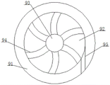
FIG. 3 is a schematic cross-sectional view of a turbine portion of a turbine type water flow cutting rotary driving mechanism in the spherical plant irrigator according to the present invention;
FIG. 4 is a schematic structural view of a water flow driven rotating mechanism in the spherical plant irrigator according to the present invention;
FIG. 5 is a schematic view of the full-section structure of the blocking connection plate in the water flow driven type rotating mechanism in the globular plant irrigator according to the present invention;
in the figure: 1, transverse supporting base plate, 2, mounting plate, 3, longitudinal supporting plate, 4, semi-annular supporting pipe, 5, component mounting housing, 6, connection port, 7, annular pipe hole, 8, component mounting space, 9, turbine water stream cut-in rotary drive mechanism, 91, turbine water stream cut-in rotary drive mechanism turbine mounting housing, 92, turbine water stream cut-in rotary drive mechanism turbine mounting space, 93, turbine water stream cut-in rotary drive mechanism rotary shaft, 94, turbine water stream cut-in rotary drive mechanism turbine, 95, turbine water stream cut-in rotary drive mechanism liquid inlet hole, 96, turbine water stream cut-in rotary drive mechanism component mounting housing structure, 97, turbine water stream cut-in rotary drive mechanism liquid discharge hole, 98, turbine water stream cut-in rotary drive mechanism mounting port, 99, turbine water flow cutting-in rotary drive mechanism bearing 10, part sleeve hole 11, water flow driven rotary mechanism 111, water flow driven rotary mechanism outer housing 112, water flow driven rotary mechanism inner housing 113, water flow driven rotary mechanism main pipe hole 114, water flow driven rotary mechanism auxiliary pipe hole 115, water flow driven rotary mechanism seal ring 116, water flow driven rotary mechanism bearing 117, water flow driven rotary mechanism separation connecting plate 118, water flow driven rotary mechanism connecting shaft 119, water flow driven rotary mechanism inclined hole 12, semi-annular housing 13, annular liquid discharge pipe hole 14, mounting hole 15, main discharge hole 16, liquid spray head 17, annular hollow housing 18, annular space 19, water discharge valve 20, main rotary shaft 21, seal ring, 22, main bearing.
Detailed Description
The technical solutions in the embodiments of the present invention will be clearly and completely described below with reference to the drawings in the embodiments of the present invention, and it is obvious that the described embodiments are only a part of the embodiments of the present invention, and not all of the embodiments. All other embodiments, which can be derived by a person skilled in the art from the embodiments given herein without making any creative effort, shall fall within the protection scope of the present invention.
Referring to fig. 1, an embodiment of the present invention: including horizontal support substrate 1 and semi-annular shell 12, its characterized in that: the upper surface of the transverse supporting substrate 1 is provided with a mounting plate 2, one side of the transverse supporting substrate 1 is provided with an annular hollow shell 17 of an integrated structure, the center of the annular hollow shell 17 is provided with an annular space 18, the bottom of the side surface of the annular hollow shell 17 is provided with a drain valve 19, the middle of the upper surface of the transverse supporting substrate 1 is provided with a longitudinal supporting plate 3, the top of the longitudinal supporting plate 3 is provided with a semi-annular supporting pipeline 4, the top end of the semi-annular supporting pipeline 4 is provided with a component mounting shell 5, the semi-annular supporting pipeline 4 is internally provided with an annular pipeline hole 7, the bottom end of the annular pipeline hole 7 is provided with a connecting port 6, the component mounting shell 5 is internally provided with a component mounting space 8, the internal part of the component mounting space 8 is provided with a turbine water flow cut-in a rotary driving mechanism 9, and the water inlet port of the turbine water flow cut-in the rotary driving mechanism, the top end of the rotating shaft inside the turbine water flow cutting and rotating mechanism 9 is connected with a main rotating shaft 20, and a main rotating shaft 20 is installed inside the component mounting housing 5 through a packing 21 and a main bearing 22, a part sleeving hole 10 is arranged at the center of the bottom of the part mounting shell 5, a water flow driven type rotating mechanism 11 is arranged at the bottom of the turbine type water flow cutting-in rotating driving mechanism 9, and rivers driven rotary mechanism 11 runs through part cup joint hole 10, the inside of semi-annular shell 12 is equipped with an annular flowing back pipeline hole 13, and the inside of semi-annular shell 12 is equipped with the mounting hole 14 of intercommunication annular flowing back pipeline hole 13 top and external space, and the bottom of rivers driven rotary mechanism 11 is installed in the inside of mounting hole 14, and the inside of semi-annular shell 12 is equipped with a plurality of central lines towards the main discharge hole 15 of its centre of a circle department, just a liquid shower nozzle 16 of internally mounted of main discharge hole 15.
Referring to fig. 2, the turbine water flow cutting-in rotation driving mechanism 9 includes a turbine mounting housing 91 for the turbine water flow cutting-in rotation driving mechanism, a turbine mounting space 92 for the turbine water flow cutting-in rotation driving mechanism, a rotation shaft 93 for the turbine water flow cutting-in rotation driving mechanism, a turbine 94 for the turbine water flow cutting-in rotation driving mechanism, a liquid inlet hole 95 for the turbine water flow cutting-in rotation driving mechanism, a member mounting housing structure 96 for the turbine water flow cutting-in rotation driving mechanism, a liquid discharge hole 97 for the turbine water flow cutting-in rotation driving mechanism, a mounting port 98 for the turbine water flow cutting-in rotation driving mechanism, and a bearing 99 for the turbine water flow cutting-in rotation driving mechanism; the turbine type water flow cutting-in and rotation driving mechanism turbine installation shell 91 is provided with a turbine type water flow cutting-in and rotation driving mechanism turbine installation space 92 at the center inside, the turbine type water flow cutting-in and rotation driving mechanism turbine installation shell 91 is provided with an integrated turbine type water flow cutting-in and rotation driving mechanism component installation shell structure 96 at the bottom, the turbine type water flow cutting-in and rotation driving mechanism turbine installation shell 91 is provided with a turbine type water flow cutting-in and rotation driving mechanism liquid inlet hole 95 at the side surface communicating with an external structure and the turbine type water flow cutting-in and rotation driving mechanism turbine installation space 92, the turbine type water flow cutting-in and rotation driving mechanism component installation shell structure 96 is provided with a turbine type water flow cutting-in and rotation driving mechanism liquid discharge hole 97 at the middle of the end surface communicating with the turbine type water flow cutting-in and rotation driving mechanism turbine installation space 92, a turbine water flow cut-in rotation drive mechanism mounting port 98 is provided at the bottom of the turbine water flow cut-in rotation drive mechanism liquid discharge hole 97, a turbine water flow cut-in rotation drive mechanism rotating shaft 93 is mounted at the center of the solid end surface of the turbine mounting case 91 for the turbine water flow cut-in rotation drive mechanism through a turbine water flow cut-in rotation drive mechanism bearing 99, and a turbine water flow cut-in rotation drive mechanism turbine 94 is mounted on a shaft body located inside the turbine mounting space 92 for the turbine water flow cut-in rotation drive mechanism rotating shaft 93; the turbine water flow cut-in rotation driving mechanism liquid inlet hole 95 is communicated with the turbine installation space 92 for the turbine water flow cut-in rotation driving mechanism in a form of being tangent to the edge of the turbine installation space 92 for the turbine water flow cut-in rotation driving mechanism; turbine formula rivers are cut into for the rotary drive mechanism turbine installation shell 91 and are installed in the inside of part installation space 8, and turbine formula rivers cut into for the rotary drive mechanism feed liquor hole 95 feed liquor tip and the top intercommunication of ring pipeline hole 7, turbine formula rivers are cut into the top of rotary drive mechanism rotation axis 93 and the bottom fixed connection of main rotation axis 20, and turbine formula rivers are cut into a water flow driven rotary mechanism 11 of internally mounted of rotary drive mechanism with installation port 98.
Referring to fig. 3, the water flow driven type rotating mechanism 11 includes an outer housing 111 for a water flow driven type rotating mechanism, an inner housing 112 for a water flow driven type rotating mechanism, a main pipe hole 113 for a water flow driven type rotating mechanism, an auxiliary pipe hole 114 for a water flow driven type rotating mechanism, a seal ring 115 for a water flow driven type rotating mechanism, a bearing 116 for a water flow driven type rotating mechanism, a blocking connection plate 117 for a water flow driven type rotating mechanism, a connection shaft 118 for a water flow driven type rotating mechanism, and an inclined hole 119 for a water flow driven type rotating mechanism; a main pipe hole 113 for a water flow driven type rotating mechanism and an auxiliary pipe hole 114 for the water flow driven type rotating mechanism are respectively arranged at the inner centers of the outer shell 111 for the water flow driven type rotating mechanism and the inner shell 112 for the water flow driven type rotating mechanism, one end of the inner shell 112 for the water flow driven type rotating mechanism is arranged at one end inside the main pipe hole 113 for the water flow driven type rotating mechanism through a sealing ring 115 for the water flow driven type rotating mechanism and a bearing 116 for the water flow driven type rotating mechanism, a separation connecting plate 117 for the water flow driven type rotating mechanism is fixedly arranged at the middle section inside the main pipe hole 113 for the water flow driven type rotating mechanism by the outer shell 111 for the water flow driven type rotating mechanism, and a plurality of annular array type inclined holes 119 for the water flow driven type rotating mechanism communicating the two end faces of the, a connecting shaft 118 for a water flow driven type rotating mechanism is arranged at the center of one end face of the blocking connecting plate 117 for the water flow driven type rotating mechanism; the outer casing 111 for the water flow driven rotation mechanism is fixedly installed inside the installation hole 14, the top end of the inner casing 112 for the water flow driven rotation mechanism is fixedly installed inside the installation port 98 for the turbine water flow cutting-in rotation driving mechanism, and the top end of the connecting shaft 118 for the water flow driven rotation mechanism is fixedly connected to the bottom end of the rotating shaft 93 for the turbine water flow cutting-in rotation driving mechanism; the direction of the slope of the inclined hole 119 for water flow driven rotation mechanism is opposite to the direction of rotation of the turbine 94 for turbine water flow cut-in rotation drive mechanism.
The specific use mode is as follows: during the operation of the invention, firstly, the device is sleeved on the surface of a spherical plant to enable the plant to be located at the center of the annular space 18, then a water pump or a drainage device is arranged on the surface of the mounting plate 2, a drainage port in the mounting device is fixedly connected with the connecting port 6 through a pipeline, when the weather is dry, the drainage valve 19 is closed, otherwise, the drainage valve 19 is opened, when the drainage device or the water pump is opened, a water source is flushed into the turbine type water flow cut-in rotary driving mechanism 9 through each pipeline hole under the high pressure state, due to the characteristic of the structure of the internal parts of the turbine type water flow cut-in rotary driving mechanism, the flushing of the water flow can drive the turbine type water flow cut-in rotary driving mechanism to rotate the turbine 94 for the rotary driving mechanism, under the action of the connecting part, the semi-annular shell 12 is further driven to rotate, and simultaneously, the flushed liquid under the flowing action, the water is sprayed to the surface of the plant through the water flow nozzle 16, so that the liquid can irrigate the surface of the plant in a rotating mode, the all-dimensional water source coverage is realized, and finally the liquid falls into the annular space 18 under the action of gravity to irrigate the root of the plant.
It will be evident to those skilled in the art that the invention is not limited to the details of the foregoing illustrative embodiments, and that the present invention may be embodied in other specific forms without departing from the spirit or essential attributes thereof. The present embodiments are therefore to be considered in all respects as illustrative and not restrictive, the scope of the invention being indicated by the appended claims rather than by the foregoing description, and all changes which come within the meaning and range of equivalency of the claims are therefore intended to be embraced therein. Any reference sign in a claim should not be construed as limiting the claim concerned.
Claims (7)
1. A spherical plant irrigator comprises a transverse supporting base plate (1) and a semi-annular shell (12), and is characterized in that: the upper surface of the transverse supporting substrate (1) is provided with a mounting plate (2), one side of the transverse supporting substrate (1) is provided with an annular hollow shell (17) of an integrated structure, the center of the annular hollow shell (17) is provided with an annular space (18), the bottom of the side surface of the annular hollow shell (17) is provided with a drainage valve (19), the middle of the upper surface of the transverse supporting substrate (1) is provided with a longitudinal supporting plate (3), the top of the longitudinal supporting plate (3) is provided with a semi-annular supporting pipeline (4), the top of the semi-annular supporting pipeline (4) is provided with a component mounting shell (5), the inside of the semi-annular supporting pipeline (4) is provided with an annular pipeline hole (7), the bottom of the annular pipeline hole (7) is provided with a connecting port (6), and the inside of the component mounting shell (5) is provided with a component mounting space (, the inside installation of part installation space (8) one turbine formula rivers cut into rotary driving mechanism (9), and turbine formula rivers cut into the water inlet port of rotary driving mechanism (9) and the top intercommunication of annular pipeline hole (6), and turbine formula rivers cut into the top of rotary driving mechanism (9) inside rotation axis and connect a main rotation axis (20), and main rotation axis (20) are installed in the inside of part installation shell (5) through sealing washer (21) and base bearing (22), part installation shell (5) bottom center is equipped with a part and cup joints hole (10), and turbine formula rivers cut into a water driven rotary mechanism (11) of bottom installation of rotary driving mechanism (9), and rivers driven rotary mechanism (11) run through part and cup joint hole (10), the inside of semi-annular shell (12) is equipped with an annular drainage pipeline hole (13), and the inside of semi-annular shell (12) is equipped with the top of intercommunication annular drainage pipeline hole (13) and external space's of annular drainage pipeline hole (13) and external space The bottom end of the water flow driven type rotating mechanism (11) is arranged in the mounting hole (14), a plurality of main discharge holes (15) with the center lines facing the circle center of the main discharge holes are formed in the semi-annular shell (12), and a liquid spray head (16) is arranged in each main discharge hole (15).
2. The spherical plant irrigator of claim 1, wherein: the turbine water flow cutting-in rotation driving mechanism (9) comprises a turbine mounting shell (91) for the turbine water flow cutting-in rotation driving mechanism, a turbine mounting space (92) for the turbine water flow cutting-in rotation driving mechanism, a rotating shaft (93) for the turbine water flow cutting-in rotation driving mechanism, a turbine (94) for the turbine water flow cutting-in rotation driving mechanism, a liquid inlet hole (95) for the turbine water flow cutting-in rotation driving mechanism, a component mounting shell structure (96) for the turbine water flow cutting-in rotation driving mechanism, a liquid discharge hole (97) for the turbine water flow cutting-in rotation driving mechanism, a mounting port (98) for the turbine water flow cutting-in rotation driving mechanism and a bearing (99) for the turbine water flow cutting-in rotation driving mechanism; the turbine type water flow cutting-in and rotating driving mechanism turbine installation shell (91) is characterized in that a turbine type water flow cutting-in and rotating driving mechanism turbine installation space (92) is arranged in the center of the turbine type water flow cutting-in and rotating driving mechanism turbine installation shell (91), an integrated turbine type water flow cutting-in and rotating driving mechanism component installation shell structure (96) is arranged at the bottom of the turbine type water flow cutting-in and rotating driving mechanism turbine installation shell (91), a turbine type water flow cutting-in and rotating driving mechanism liquid inlet hole (95) which is communicated with an external structure and the turbine type water flow cutting-in and rotating driving mechanism turbine installation space (92) is formed in the side face of the turbine type water flow cutting-in and rotating driving mechanism turbine installation shell (91), a turbine type water flow cutting-in and rotating driving mechanism turbine installation space (92) end face middle portion turbine type water flow cutting-in and rotating driving mechanism liquid, the bottom that rotary drive mechanism used liquid discharge hole (97) was cut into to turbo type rivers is equipped with turbo type rivers and cuts into installation port (98) for rotary drive mechanism, turbo type rivers are cut into the solid terminal surface center of rotary drive mechanism used turbine installation shell (91) and are cut into rotary drive mechanism through turbo type rivers and install a turbo type rivers and cut into rotary drive mechanism and use rotation axis (93), turbo type rivers are cut into rotary drive mechanism and are used rotation axis (93) and lie in turbo type rivers cut into rotary drive mechanism and cut into turbine for rotary drive mechanism turbine installation space (92) inside axis body on installation a turbo type rivers cut into rotary drive mechanism and use turbine (94).
3. The spherical plant irrigator of claim 2, wherein: the liquid inlet hole (95) for the turbine type water flow cutting-in rotary driving mechanism is communicated with the turbine installation space (92) for the turbine type water flow cutting-in rotary driving mechanism in a mode of being tangent to the edge of the turbine installation space (92) for the turbine type water flow cutting-in rotary driving mechanism.
4. The spherical plant irrigator of claim 2, wherein: turbine formula rivers are cut into rotary drive for mechanism turbine installation shell (91) and are installed in the inside of part installation space (8), and turbine formula rivers cut into rotary drive for mechanism feed liquor hole (95) feed liquor tip and annular pipeline hole (7) top intercommunication, turbine formula rivers are cut into the top of rotary drive for mechanism rotation axis (93) and the bottom fixed connection of main rotation axis (20), and turbine formula rivers are cut into a water flow driven rotary mechanism (11) of internally mounted of rotary drive for mechanism installation port (98).
5. The spherical plant irrigator of claim 1, wherein: the water flow driven type rotating mechanism (11) comprises an outer shell (111) for the water flow driven type rotating mechanism, an inner shell (112) for the water flow driven type rotating mechanism, a main pipeline hole (113) for the water flow driven type rotating mechanism, an auxiliary pipeline hole (114) for the water flow driven type rotating mechanism, a sealing ring (115) for the water flow driven type rotating mechanism, a bearing (116) for the water flow driven type rotating mechanism, a separation connecting plate (117) for the water flow driven type rotating mechanism, a connecting shaft (118) for the water flow driven type rotating mechanism and an inclined hole (119) for the water flow driven type rotating mechanism; a main pipeline hole (113) for a water flow driven type rotating mechanism and an auxiliary pipeline hole (114) for the water flow driven type rotating mechanism are respectively arranged at the inner centers of an outer shell (111) for a water flow driven type rotating mechanism and an inner shell (112) for the water flow driven type rotating mechanism, one end of the inner shell (112) for the water flow driven type rotating mechanism is arranged at one end inside the main pipeline hole (113) for the water flow driven type rotating mechanism through a sealing ring (115) for the water flow driven type rotating mechanism and a bearing (116) for the water flow driven type rotating mechanism, a separation connecting plate (117) for the water flow driven type rotating mechanism is fixedly arranged at the middle section inside the main pipeline hole (113) for the water flow driven type rotating mechanism, and a plurality of annular arrayed oblique holes (119) for the water flow driven type rotating mechanism, which are communicated with the two end faces, are arranged inside the separation connecting plate (117) for the, and a connecting shaft (118) for the water flow driven type rotating mechanism is arranged at the center of one end face of the separation connecting plate (117) for the water flow driven type rotating mechanism.
6. The spherical plant irrigator of claim 5, wherein: the water flow driven type rotating mechanism is fixedly installed inside the installation hole (14) through the outer shell (111), the top end of the inner shell (112) for the water flow driven type rotating mechanism is fixedly installed inside the installation port (98) for the turbine type water flow cutting-in rotating driving mechanism, and the top end of the connecting shaft (118) for the water flow driven type rotating mechanism is fixedly connected with the bottom end of the rotating shaft (93) for the turbine type water flow cutting-in rotating driving mechanism.
7. The spherical plant irrigator of claim 5, wherein: the direction of the slope of the inclined hole (119) for the water flow driven type rotating mechanism is opposite to the rotating direction of the turbine type water flow cutting into the turbine (94) for the rotating mechanism.
Priority Applications (1)
| Application Number | Priority Date | Filing Date | Title |
|---|---|---|---|
| CN202010561623.1A CN111642363B (en) | 2020-06-18 | 2020-06-18 | Spherical plant irrigator |
Applications Claiming Priority (1)
| Application Number | Priority Date | Filing Date | Title |
|---|---|---|---|
| CN202010561623.1A CN111642363B (en) | 2020-06-18 | 2020-06-18 | Spherical plant irrigator |
Publications (2)
| Publication Number | Publication Date |
|---|---|
| CN111642363A true CN111642363A (en) | 2020-09-11 |
| CN111642363B CN111642363B (en) | 2021-10-29 |
Family
ID=72341221
Family Applications (1)
| Application Number | Title | Priority Date | Filing Date |
|---|---|---|---|
| CN202010561623.1A Active CN111642363B (en) | 2020-06-18 | 2020-06-18 | Spherical plant irrigator |
Country Status (1)
| Country | Link |
|---|---|
| CN (1) | CN111642363B (en) |
Citations (22)
| Publication number | Priority date | Publication date | Assignee | Title |
|---|---|---|---|---|
| CN101585022A (en) * | 2009-01-20 | 2009-11-25 | 厦门松霖科技有限公司 | Rotary-sprinkling sprinkler |
| CN203735192U (en) * | 2014-02-25 | 2014-07-30 | 杭州中艺园林工程有限公司 | Crown water supplementing mechanism for large nursery trees |
| CN203896925U (en) * | 2014-06-18 | 2014-10-29 | 台州黄岩翁氏塑料厂 | Rotary sprinkler |
| CN203912771U (en) * | 2014-06-30 | 2014-11-05 | 李洪 | Rural area irrigation system |
| US20150196001A1 (en) * | 2014-01-13 | 2015-07-16 | Johnny Green | Irrigation Systems |
| EP3095319A1 (en) * | 2015-05-22 | 2016-11-23 | Irrimec S.r.l. | A sprinkler irrigation plant with a self-propelling drum and a activating method |
| CN106171842A (en) * | 2016-06-29 | 2016-12-07 | 卢杨 | Sprinkler for green area irrigation |
| CN206642947U (en) * | 2017-03-27 | 2017-11-17 | 湖南工艺美术职业学院 | A kind of outdoor artistic fountain |
| CN107366328A (en) * | 2017-07-26 | 2017-11-21 | 西南林业大学 | A kind of treegarden irrigation rain collector |
| CN108331695A (en) * | 2017-12-21 | 2018-07-27 | 中国农业大学 | A kind of hydroturbine |
| CN207854686U (en) * | 2017-11-24 | 2018-09-14 | 唐浩 | A kind of irrigation tap that can be rotated automatically |
| CN108892594A (en) * | 2018-09-27 | 2018-11-27 | 潍坊工程职业学院 | A kind of plant nutrition liquid enhancing sprigging survival rate |
| CN108934940A (en) * | 2018-06-08 | 2018-12-07 | 山东农业大学 | A kind of self-powered rotary irrigation device |
| CN109122210A (en) * | 2017-06-15 | 2019-01-04 | 淄博华源矿业有限公司 | Afforest automatic irrigation device |
| CN208480279U (en) * | 2018-03-28 | 2019-02-12 | 南安市奇优机械设计有限公司 | A kind of agricultural irrigation equipment |
| CN208807275U (en) * | 2018-09-18 | 2019-05-03 | 齐永盛 | A kind of cuttage and seedling culture spraying machine |
| US20190133059A1 (en) * | 2012-01-26 | 2019-05-09 | Robert E. DeWitt | Water sprinkler for spraying a select depth of water per unit area onto one or a group of ground areas of any shape and relative size |
| RU2691569C1 (en) * | 2018-11-12 | 2019-06-14 | Федеральное государственное бюджетное образовательное учреждение высшего образования "Донской государственный аграрный университет" (ФГБОУ ВО Донской ГАУ) | Sprinkler apparatus |
| CN209030768U (en) * | 2018-10-11 | 2019-06-28 | 北京碧云龙园林绿化工程有限公司 | A kind of landscape engineering Water saving type watering arrangement |
| CN110463581A (en) * | 2019-09-09 | 2019-11-19 | 刘冬冬 | A kind of environment-friendly type greening lawn Irrigation shower head |
| CN110679442A (en) * | 2019-11-06 | 2020-01-14 | 江苏翔宇灌溉设备有限公司 | Movable sprinkler |
| CN210168652U (en) * | 2019-06-26 | 2020-03-24 | 余隽 | A water-saving irrigation device for landscape plant plants |
-
2020
- 2020-06-18 CN CN202010561623.1A patent/CN111642363B/en active Active
Patent Citations (22)
| Publication number | Priority date | Publication date | Assignee | Title |
|---|---|---|---|---|
| CN101585022A (en) * | 2009-01-20 | 2009-11-25 | 厦门松霖科技有限公司 | Rotary-sprinkling sprinkler |
| US20190133059A1 (en) * | 2012-01-26 | 2019-05-09 | Robert E. DeWitt | Water sprinkler for spraying a select depth of water per unit area onto one or a group of ground areas of any shape and relative size |
| US20150196001A1 (en) * | 2014-01-13 | 2015-07-16 | Johnny Green | Irrigation Systems |
| CN203735192U (en) * | 2014-02-25 | 2014-07-30 | 杭州中艺园林工程有限公司 | Crown water supplementing mechanism for large nursery trees |
| CN203896925U (en) * | 2014-06-18 | 2014-10-29 | 台州黄岩翁氏塑料厂 | Rotary sprinkler |
| CN203912771U (en) * | 2014-06-30 | 2014-11-05 | 李洪 | Rural area irrigation system |
| EP3095319A1 (en) * | 2015-05-22 | 2016-11-23 | Irrimec S.r.l. | A sprinkler irrigation plant with a self-propelling drum and a activating method |
| CN106171842A (en) * | 2016-06-29 | 2016-12-07 | 卢杨 | Sprinkler for green area irrigation |
| CN206642947U (en) * | 2017-03-27 | 2017-11-17 | 湖南工艺美术职业学院 | A kind of outdoor artistic fountain |
| CN109122210A (en) * | 2017-06-15 | 2019-01-04 | 淄博华源矿业有限公司 | Afforest automatic irrigation device |
| CN107366328A (en) * | 2017-07-26 | 2017-11-21 | 西南林业大学 | A kind of treegarden irrigation rain collector |
| CN207854686U (en) * | 2017-11-24 | 2018-09-14 | 唐浩 | A kind of irrigation tap that can be rotated automatically |
| CN108331695A (en) * | 2017-12-21 | 2018-07-27 | 中国农业大学 | A kind of hydroturbine |
| CN208480279U (en) * | 2018-03-28 | 2019-02-12 | 南安市奇优机械设计有限公司 | A kind of agricultural irrigation equipment |
| CN108934940A (en) * | 2018-06-08 | 2018-12-07 | 山东农业大学 | A kind of self-powered rotary irrigation device |
| CN208807275U (en) * | 2018-09-18 | 2019-05-03 | 齐永盛 | A kind of cuttage and seedling culture spraying machine |
| CN108892594A (en) * | 2018-09-27 | 2018-11-27 | 潍坊工程职业学院 | A kind of plant nutrition liquid enhancing sprigging survival rate |
| CN209030768U (en) * | 2018-10-11 | 2019-06-28 | 北京碧云龙园林绿化工程有限公司 | A kind of landscape engineering Water saving type watering arrangement |
| RU2691569C1 (en) * | 2018-11-12 | 2019-06-14 | Федеральное государственное бюджетное образовательное учреждение высшего образования "Донской государственный аграрный университет" (ФГБОУ ВО Донской ГАУ) | Sprinkler apparatus |
| CN210168652U (en) * | 2019-06-26 | 2020-03-24 | 余隽 | A water-saving irrigation device for landscape plant plants |
| CN110463581A (en) * | 2019-09-09 | 2019-11-19 | 刘冬冬 | A kind of environment-friendly type greening lawn Irrigation shower head |
| CN110679442A (en) * | 2019-11-06 | 2020-01-14 | 江苏翔宇灌溉设备有限公司 | Movable sprinkler |
Non-Patent Citations (2)
| Title |
|---|
| 汤玲迪等: "卷盘式喷灌机研究进展与发展趋势分析", 《农业机械学报》 * |
| 范永申等: "喷灌和软管灌溉两用轻小机组特性", 《排灌机械》 * |
Also Published As
| Publication number | Publication date |
|---|---|
| CN111642363B (en) | 2021-10-29 |
Similar Documents
| Publication | Publication Date | Title |
|---|---|---|
| CN111642363B (en) | Spherical plant irrigator | |
| CN218637645U (en) | Self-rotating spray head | |
| CN101518762B (en) | Rotary water supply device used for spraying system | |
| CN206389925U (en) | A kind of reel sprinkling irrigation machine energy-saving power device | |
| CN101554621B (en) | Self-rotating sprayer | |
| CN210275400U (en) | Irrigation and water conservancy's spraying machine | |
| CN210726257U (en) | Water-saving irrigation sprinkling irrigation device | |
| CN212835669U (en) | Gradually-opened fire hydrant | |
| CN211832213U (en) | A water conservation curing means for transplanting gardens nursery stock | |
| CN201361591Y (en) | Rotary water supply device used for spraying system | |
| CN210876612U (en) | High-efficient cleaning head of autogyration magnetic force speed limit | |
| CN212337714U (en) | Sewage pump mechanism for pre-discharging substances around impact | |
| CN201431936Y (en) | Self-rotary sprayer | |
| CN216147042U (en) | Rotary spraying type aerator | |
| CN112031991B (en) | Fan blade cleaning device for wind driven generator | |
| CN215530581U (en) | Irrigation device for hydraulic engineering | |
| CN2669999Y (en) | Rotary irrigatnig nozzles | |
| CN113042238B (en) | Rotatable shower nozzle structure and controlling means thereof | |
| CN217069284U (en) | A rotatory nozzle for lifting and dropping irrigation dives | |
| CN219024659U (en) | High-pressure rotary spray head | |
| CN218777670U (en) | Water jet driven eddy adsorption brush | |
| CN216795999U (en) | Irrigation equipment that farming used | |
| CN211631181U (en) | Quick response sprinkler head | |
| CN218483429U (en) | Municipal works gardens sprinkler | |
| CN211721345U (en) | Agricultural water-saving irrigation device |
Legal Events
| Date | Code | Title | Description |
|---|---|---|---|
| PB01 | Publication | ||
| PB01 | Publication | ||
| SE01 | Entry into force of request for substantive examination | ||
| SE01 | Entry into force of request for substantive examination | ||
| GR01 | Patent grant | ||
| GR01 | Patent grant |