CN111641578B - Wireless communication method, station and storage medium - Google Patents
Wireless communication method, station and storage medium Download PDFInfo
- Publication number
- CN111641578B CN111641578B CN202010424068.8A CN202010424068A CN111641578B CN 111641578 B CN111641578 B CN 111641578B CN 202010424068 A CN202010424068 A CN 202010424068A CN 111641578 B CN111641578 B CN 111641578B
- Authority
- CN
- China
- Prior art keywords
- resources
- resource
- configuration
- different
- message
- Prior art date
- Legal status (The legal status is an assumption and is not a legal conclusion. Google has not performed a legal analysis and makes no representation as to the accuracy of the status listed.)
- Active
Links
Images


Classifications
-
- H—ELECTRICITY
- H04—ELECTRIC COMMUNICATION TECHNIQUE
- H04L—TRANSMISSION OF DIGITAL INFORMATION, e.g. TELEGRAPHIC COMMUNICATION
- H04L27/00—Modulated-carrier systems
- H04L27/26—Systems using multi-frequency codes
- H04L27/2601—Multicarrier modulation systems
- H04L27/2602—Signal structure
-
- H—ELECTRICITY
- H04—ELECTRIC COMMUNICATION TECHNIQUE
- H04L—TRANSMISSION OF DIGITAL INFORMATION, e.g. TELEGRAPHIC COMMUNICATION
- H04L5/00—Arrangements affording multiple use of the transmission path
- H04L5/0001—Arrangements for dividing the transmission path
- H04L5/0003—Two-dimensional division
- H04L5/0005—Time-frequency
- H04L5/0007—Time-frequency the frequencies being orthogonal, e.g. OFDM(A), DMT
- H04L5/001—Time-frequency the frequencies being orthogonal, e.g. OFDM(A), DMT the frequencies being arranged in component carriers
-
- H—ELECTRICITY
- H04—ELECTRIC COMMUNICATION TECHNIQUE
- H04L—TRANSMISSION OF DIGITAL INFORMATION, e.g. TELEGRAPHIC COMMUNICATION
- H04L5/00—Arrangements affording multiple use of the transmission path
- H04L5/0091—Signaling for the administration of the divided path
- H04L5/0094—Indication of how sub-channels of the path are allocated
-
- H—ELECTRICITY
- H04—ELECTRIC COMMUNICATION TECHNIQUE
- H04L—TRANSMISSION OF DIGITAL INFORMATION, e.g. TELEGRAPHIC COMMUNICATION
- H04L27/00—Modulated-carrier systems
- H04L27/26—Systems using multi-frequency codes
-
- H—ELECTRICITY
- H04—ELECTRIC COMMUNICATION TECHNIQUE
- H04L—TRANSMISSION OF DIGITAL INFORMATION, e.g. TELEGRAPHIC COMMUNICATION
- H04L5/00—Arrangements affording multiple use of the transmission path
- H04L5/003—Arrangements for allocating sub-channels of the transmission path
-
- H—ELECTRICITY
- H04—ELECTRIC COMMUNICATION TECHNIQUE
- H04L—TRANSMISSION OF DIGITAL INFORMATION, e.g. TELEGRAPHIC COMMUNICATION
- H04L5/00—Arrangements affording multiple use of the transmission path
- H04L5/003—Arrangements for allocating sub-channels of the transmission path
- H04L5/0048—Allocation of pilot signals, i.e. of signals known to the receiver
- H04L5/0051—Allocation of pilot signals, i.e. of signals known to the receiver of dedicated pilots, i.e. pilots destined for a single user or terminal
-
- H—ELECTRICITY
- H04—ELECTRIC COMMUNICATION TECHNIQUE
- H04L—TRANSMISSION OF DIGITAL INFORMATION, e.g. TELEGRAPHIC COMMUNICATION
- H04L5/00—Arrangements affording multiple use of the transmission path
- H04L5/003—Arrangements for allocating sub-channels of the transmission path
- H04L5/0053—Allocation of signaling, i.e. of overhead other than pilot signals
-
- H—ELECTRICITY
- H04—ELECTRIC COMMUNICATION TECHNIQUE
- H04W—WIRELESS COMMUNICATION NETWORKS
- H04W72/00—Local resource management
- H04W72/04—Wireless resource allocation
- H04W72/044—Wireless resource allocation based on the type of the allocated resource
- H04W72/0446—Resources in time domain, e.g. slots or frames
-
- H—ELECTRICITY
- H04—ELECTRIC COMMUNICATION TECHNIQUE
- H04W—WIRELESS COMMUNICATION NETWORKS
- H04W72/00—Local resource management
- H04W72/04—Wireless resource allocation
- H04W72/044—Wireless resource allocation based on the type of the allocated resource
- H04W72/0453—Resources in frequency domain, e.g. a carrier in FDMA
-
- H—ELECTRICITY
- H04—ELECTRIC COMMUNICATION TECHNIQUE
- H04W—WIRELESS COMMUNICATION NETWORKS
- H04W72/00—Local resource management
- H04W72/20—Control channels or signalling for resource management
- H04W72/23—Control channels or signalling for resource management in the downlink direction of a wireless link, i.e. towards a terminal
Abstract
Systems and methods for multi-resource set configuration include obtaining a configuration associated with a physical layer (PHY) channel. The present system selects a set of resources from the plurality of resources that correspond to the configuration. The present system determines the actual resources from the selected set of resources. The present system then causes the transceiver to transmit or receive the corresponding PHY signal on the determined actual resource.
Description
The application is a divisional application with the application date of PCT international patent application PCT/CN2018/119232 of 2018, 12, month and 4, entering the China national stage, namely China patent application number 201880065850.6 and the invention name of multi-resource set configuration.
Technical Field
This specification relates generally to wireless communication networks, and more particularly, for example, but not by way of limitation, to multi-resource set configuration.
Background
In fourth generation (4G) Long Term Evolution (LTE) broadband cellular network technologies, the time and frequency resources of the physical layer (PHY) channel are directly indicated by Downlink (DL) control information (DCI). For DL or Uplink (UL) PHY channels, only one resource indication method is used. Scheduling granularity (scheduling granularity) in the time domain is represented by time slots or subframes, while scheduling of multiple sites in the frequency domain occupies different portions of the cell system bandwidth.
In fifth generation (5G) broadband cellular network technologies, there is an increased demand for scheduling flexibility in the time and frequency domains. In the time domain, scheduling is based on slot level and symbol level. In the frequency domain, the scheduling range is divided into fractional Bandwidths (BWPs), which may be different for different stations. As in 4G LTE, code domain resources are indicated for certain PHY control channels.
Drawings
Fig. 1 is a diagram illustrating a wireless communication system in accordance with one or more embodiments.
Fig. 2 is a diagram illustrating a wireless communication device including a host device and an associated radio device in accordance with one or more embodiments.
FIG. 3 illustrates a flow diagram of an example process for determining resources from a configured set of resources.
Fig. 4 illustrates a flow diagram of an example process for determining resources from different sets of resources configured for different DM-RS mapping types, in accordance with one or more embodiments.
Fig. 5 illustrates a flow diagram of an example process for determining resources from different resource sets configured for different BWP configurations in accordance with one or more embodiments.
Fig. 6 illustrates a flow diagram of an example process for determining resources from different sets of resources configured for different component carrier configurations in accordance with one or more embodiments.
Fig. 7 illustrates a flow diagram of an example process for determining resources from different sets of resources configured for different serving cell configurations in accordance with one or more embodiments.
Fig. 8 illustrates a flow diagram of an example process for determining resources from different sets of resources configured for different transmission waveforms or multiple access configurations in accordance with one or more embodiments.
FIG. 9 illustrates a flow diagram of an example process for determining resources from different sets of resources configured for different control resource sets/search space configurations in accordance with one or more embodiments.
Figure 10 conceptually illustrates an electronic system that may be used to implement one or more embodiments of the present technology.
Detailed Description
The detailed description set forth below is intended to describe various embodiments and is not intended to represent the only embodiments in which the present technology may be practiced. The accompanying drawings are incorporated herein and constitute a part of the detailed description. The detailed description includes specific details for the purpose of providing a thorough understanding of the present technology. However, the present techniques are not limited to the specific details set forth herein, and may be practiced without one or more of these specific details. As those skilled in the art will recognize, the described implementations may be modified in various different ways without departing from the scope of the present disclosure. Accordingly, the drawings and description are to be regarded as illustrative in nature, and not as restrictive. In one or more examples, structures and components are shown in block diagram form in order to avoid obscuring the concepts of the present technology.
In 4G LTE, the same set of resources is configured for PHY channels regardless of the configuration in other domains. However, the potential for flexible scheduling with acceptable signaling overhead of 5G systems cannot be fully exploited by direct DCI indication methods. The present technology provides for configuring different sets of resources corresponding to different configurations in at least one of the following domains: demodulation reference signal (DM-RS) mapping type, fractional Bandwidth (BWP) configuration, component Carrier (CC), serving cell, transmission waveform or multiple access scheme, PDCCH configuration. By configuring a different set of resources in each of the above domains, the number of resources can be doubled. Thus, the present technique provides a new approach that can achieve much greater flexibility than the traditional 4G LTE approach without any additional PHY signaling overhead.
It should be understood that the technical solution of the embodiments of the present application may be applied to various communication systems, such as a new air interface fifth generation broadband cellular network system (abbreviated as "5G"), a Long Term Evolution (Long Term Evolution, abbreviated as "LTE") broadband cellular network system, and other future communication systems.
A station described herein in connection with various embodiments may also refer to a User terminal Equipment (UE), an access terminal, a subscriber unit, a subscriber station, a mobile station, a remote terminal, a mobile device, a User terminal, a terminal device, a wireless communication device, a User agent, or User Equipment. A station may be a smartphone, a cellular phone, a cordless phone, a Session Initiation Protocol (SIP) phone, a Wireless Local Loop (WLL) station, a Personal Digital Assistant (PDA), a handheld device with Wireless communication capability, a computing device or other processing device connected to a Wireless modem, a vehicle-mounted device, a wearable device, a terminal device in a 5G broadband cellular network, or a terminal device in a future evolved Public Land Mobile Network (PLMN), etc.
Various embodiments are described herein in connection with a network device. The network device may be a device for communicating with the terminal device, for example, the network device may be an evolved Node B (eNB) or an eNodeB in an LTE system, may be a fifth Generation broadband cellular network base station (Next Generation Node B, gNB or gnnodeb), or may be a relay station, an access point, a vehicle-mounted device, a wearable device, or a network-side device of a future broadband cellular network, and the like.
As used herein, the term "downlink control information" or simply "DCI" generally refers to a specific set of information describing an uplink resource allocation for scheduling a downlink data channel (e.g., PDSCH) or an uplink data channel (e.g., PUSCH). In some aspects, the DCI includes an indication of downlink data to transmit to the UE. As used herein, the term "partial bandwidth" or simply "BWP" generally refers to a set of contiguous physical resource blocks selected from a subset of contiguous common resource blocks of a given set of parameters (numerology) on a given carrier. As used herein, the term "control resource set," or "CORESET," generally refers to a set consisting of a plurality of resource blocks in the frequency domain and an integer number of Orthogonal Frequency Division Multiplexing (OFDM) symbols in the time domain, wherein each resource block includes a plurality of resource elements (resource elements) consisting of one subcarrier in the frequency domain and one OFDM symbol in the time domain, respectively. As used herein, the term "radio resource control signaling" or referred to as "RRC signaling" generally refers to a control mechanism for controlling radio resources required for wireless communication between a UE and a base station by exchanging information about configured radio resources between the UE and the base station.
Fig. 1 is a diagram illustrating a wireless communication system 100 in accordance with one or more embodiments. Not all of the depicted components may be required; however, one or more embodiments may include additional components not shown in the figures. The arrangement and type of components may be varied without departing from the scope of the claims set out herein. Additional components, different components, or fewer components may be provided.
The wireless communication system 100 includes base stations and/or access points 112, 116, wireless communication devices 118-132, and a central node 134. It is noted that the central node 134 comprises core network equipment, which or parts of the functionality of the core network equipment (e.g. user plane functionality) may be integrated into the base station and/or the access point 112. It is also noted that the wireless communication devices 118-132 may be laptop computers 118 and 126, personal digital assistant hosts 120 and 130, personal computer hosts 124 and 132, tablet host 122, cellular telephone host 128, or other sites as described above.
Base stations or access points 112, 116 are located within service areas 111 and 113, respectively, and are operatively coupled to central node 134 via local area network connections 136, 138. Such a connection provides a connection for the base stations or access points 112, 116 to other devices within the wireless communication system 100 and to other networks via the WAN connection 142. Each base station or access point 112, 116 has an associated antenna or antenna array for communicating with wireless communication devices 118-132 within service areas 111 and 113. In one or more embodiments, base station or access point 112 wirelessly communicates with wireless communication devices 118 and 120 at the same time that base station or access point 116 wirelessly communicates with wireless communication devices 126-132. The wireless communication devices 118-132 may register with a particular base station or access point 112, 116 to receive service from the wireless communication system 100.
According to some embodiments, the base station is for a broadband cellular network system (e.g., 5G, LTE, advanced Mobile Phone Service (AMPS), digital AMPS, GSM, CDMA, local Multipoint Distribution System (LMDS), multiple Multipoint Distribution System (MMDS), enhanced data rates for GSM evolution (EDGE), general Packet Radio Service (GPRS), high Speed Downlink Packet Access (HSDPA), high speed uplink packet access (HSUPA and/or variants thereof), and the like), while the access point is for an indoor or in-building wireless network (e.g., IEEE 802.11, bluetooth, zigBee, any other type of radio frequency based network protocol and/or variants thereof), regardless of the particular type of communication system, each wireless communication device includes a built-in wireless device and/or is coupled to a wireless device.
Fig. 2 illustrates an exemplary wireless communication device 200 in accordance with one or more embodiments of the present technology. Not all of the depicted components may be required; however, one or more embodiments may include additional components not shown in the figures. The arrangement and type of the components may be varied without departing from the scope of the claims set out herein. Additional components, different components, or fewer components may be provided.
The wireless communication device 200 includes a Radio Frequency (RF) antenna 210, a duplexer circuit 215, a transceiver circuit 205, a memory 250, a processor 260, a Local Oscillator Generator (LOGEN) 270, and a power supply circuit 280. The transceiver circuit 205 includes a receiver circuit 220 and a transmitter circuit 230. The wireless communication device 200 also includes baseband processing circuitry 240. The baseband processing circuit 240 is typically separate from the transceiver. In another example, the baseband processing circuit 240 may also be integrated with the transceiver to form one component (as shown in fig. 2). In various embodiments of the present technology, one or more of the blocks shown in fig. 2 may be integrated on one or more semiconductor substrates. For example, blocks 220-270 may be implemented in a single chip or a single system-on-a-chip, or may be implemented in a chipset of multiple chips. In various embodiments, one or more blocks may be added. In various embodiments, one or more blocks shown may be removed or replaced with one or more other blocks. The wireless communication device 200 corresponds to the wireless communication device 128 or includes at least a portion of the wireless communication device 128.
The duplexer circuit 215 may provide isolation in the transmit band to avoid saturation of the receiver circuit 220 or damage to components of the receiver circuit 220, as well as to relax one or more design requirements of the receiver circuit 220. In addition, the duplexer circuit 215 may attenuate noise in the receive frequency band. The diplexer circuit 215 may be operable in multiple frequency bands under various standards (e.g., wireless standards, broadband cellular standards). The duplexer circuitry 215 may include a transmit/receive (T/R) switch for selecting a receive or transmit mode of the wireless communication device 200. The T/R switch may be controlled by the baseband processing circuit 240.
The receiver circuitry 220 may comprise suitable logic and/or code that may be operable to receive and process an incoming RF signal from the RF antenna 210. For example, receiver circuit 220 may be used to amplify and/or downconvert (down-convert) a received wireless signal. In some embodiments of the present technology, the receiver circuit 220 may be used to cancel noise in the received signal and may be linear over a wide range of frequencies. In this manner, receiver circuit 220 may be adapted to receive signals in accordance with various wireless standards and broadband cellular standards. By way of non-limiting example, such standards may include 5G, 4G LTE, 3G, GSM, wi-Fi, wiMAX, and Bluetooth.
The transmitter circuitry 230 may comprise suitable logic and/or code that may be operable to process and transmit signals from the RF antenna 210. For example, transmitter circuitry 230 may be used to up-convert (up-convert) the baseband processed signal to an output RF signal and amplify the output RF signal. In some embodiments of the present technology, transmitter circuitry 230 may be used to up-convert and amplify baseband signals processed according to various wireless standards. In some embodiments of the present technology, the transmitter circuit 230 may be used to provide further amplification of the signal by one or more power amplifiers. In one or more embodiments, the transmitter circuit 230 includes a power amplifier for amplifying the output RF signal.
The baseband processing circuit 240 may comprise suitable logic, circuitry, interfaces and/or code that may be operable to perform processing of baseband signals. For example, the baseband processing circuits 240 may analyze the received signals and generate control signals and/or feedback signals for configuring various components of the wireless communication device 200 (e.g., the receiver circuit 220). The baseband processing circuit 240 may be used to encode, decode, transcode, modulate, demodulate, encrypt, decrypt, scramble, descramble, and/or otherwise process data in accordance with one or more broadband cellular standards.
The memory 250 may comprise suitable logic, circuitry, and/or code that may be enabled to store various types of information (e.g., received data, generated data, code, and/or configuration information). For example, memory 250 may include Random Access Memory (RAM), read Only Memory (ROM), flash memory, and/or magnetic memory. In some implementations of the present technology, the information stored in the memory 250 may be used to configure the receiver circuitry 220 and/or the baseband processing circuitry 240.
The processor 260 may comprise suitable logic, circuitry, and/or code that may enable processing data for the wireless communication device 200 and/or controlling the operation of the wireless communication device 200. In this regard, the processor 260 is capable of providing control signals to various other portions of the wireless communication device 200. The processor 260 may also control the transfer of data between various portions of the wireless communication device 200. Further, the processor 260 can implement an operating system or execute code to manage the operation of the wireless communication device 200.
The Local Oscillator Generator (LOGEN) 270 may comprise suitable logic, circuitry, interfaces and/or code that may be operable to generate one or more oscillating signals at one or more frequencies. LOGEN 270 may be used to generate digital and/or analog signals. In this manner, LOGEN 270 may be used to generate one or more clock signals and/or sinusoidal signals. For example, characteristics of the oscillating signal, such as frequency and duty cycle, may be determined based on one or more control signals from processor 260 and/or baseband processing circuitry 240. In one or more embodiments, the LOGEN 270 may employ a crystal oscillator to generate the clock signal and/or the sinusoidal signal.
The power circuitry 280 may comprise suitable logic, circuitry, and/or code that may be operable to provide power (e.g., regulated voltage) to components within the wireless communication device 200. For example, the power supply circuit 280 may provide power to the duplexer circuit 215, the receiver circuit 220, the transmitter circuit 230, the baseband processing circuit 240, the memory 250, the processor 260, and the LOGEN 270.
In operation, the processor 260 may configure the various components of the wireless communication device 200 based on the standard under which the wireless communication device 200 receives signals. The wireless signal may be received via the RF antenna 210, amplified and downconverted by a receiver circuit 220. The baseband processing circuit 240 may perform noise estimation and/or noise cancellation of the baseband signal, decoding and/or demodulation of the baseband signal. In this way, the information in the received signal can be properly recovered and utilized. For example, the information may be audio, text, images, video, multimedia, and/or control signals to be presented to a user of the wireless communication device 200, may be data to be stored to the memory 250, and/or information that affects and/or enables operation of the wireless communication device 200. Baseband processing circuitry 240 may modulate, encode, and perform other processing for audio, text, image, video, multimedia, and/or control signals to be transmitted by transmitter circuitry 230 in accordance with various standards. The power supply circuit 280 may provide one or more regulated rail voltages for various components of the wireless communication device 200.
In some broadband cellular network standards, such as 5G, the physical channels may be divided into downlink channels, such as a Physical Downlink Shared Channel (PDSCH) and a Physical Downlink Control Channel (PDCCH), and uplink channels, such as a Physical Uplink Shared Channel (PUSCH) and a Physical Uplink Control Channel (PUCCH). The PDCCH signal is used to transmit downlink control information that informs the user equipment about resource allocation or scheduling of downlink resource allocation, uplink resource grant, and uplink power control command on the PDSCH. Demodulating, at a user equipment, a PDCCH signal based on a cell-specific reference signal (CRS). In a 5G broadband cellular network system, a starting symbol in a physical resource block (abbreviated "PRB") may indicate control information (e.g., downlink control information, abbreviated "DCI") in a downlink transmission.
It should also be understood that in embodiments of the present technology, the physical resources may include time domain resources and frequency domain resources. In the time domain, the resource occupies M symbols (e.g., OFDM symbols), where M is a positive integer equal to or greater than 1. In the frequency domain, the frequency domain resources occupy N units, where each of the N units includes K consecutive subcarriers in the frequency domain, where N is a positive integer greater than or equal to 1, and K is a positive integer equal to or greater than 2. The physical resources may also include at least one of time and frequency domain resources, code domain resources, or spatial domain resources.
FIG. 3 illustrates a flow diagram of an example process 300 for determining resources from a configured set of resources. Further, for illustrative purposes, the blocks of process 300 are described herein as occurring serially or linearly. However, multiple blocks of the process 300 may occur in parallel. Additionally, the blocks of the process 300 need not be performed in the order shown, and/or one or more blocks of the process 300 need not be performed and/or may be replaced by other operations.
In 4G LTE, the same set of resources is configured for PHY channels regardless of the configuration in other domains. In order to keep the DCI within an acceptable signaling overhead range, a very limited bit width is used in the resource allocation bit field of the DCI, and thus the number of configurable resources is greatly limited. A combination of RRC configuration and DCI indication may be used for resource allocation in a 5G system, e.g., by RRC signaling to configure a candidate resource set, and then DCI indicates an index of resources in a "resource table" or "resource set" depicted in fig. 3.
In this regard, the process 300 begins at step 301, where a station (e.g., 128, 200) determines an actual resource from N resources in a configured set of resources, where N is a positive integer. Next, at step 302, the station occupies the determined resources to receive PDSCH signals in downlink transmission from the base station (e.g., 116) or to transmit PDSCH/PUCCH signals in uplink transmission to the base station. However, since the acceptable DCI signaling overhead is greatly limited, the bit-field width for resource allocation may be only 2 to 6 bits wide. With this limited bit width, the configured resource set (or table) can only contain N =4-64 resources.
Considering that multiple dimensions, such as a starting slot, a number of slots, a starting symbol, a number of symbols in a slot, a starting Physical Resource Block (PRB), a number of PRBs, code domain parameters (e.g., sequence index, cyclic Shift (CS) index, orthogonal mask (OCC) index), and frequency hopping parameters (e.g., frequency hopping on/off, frequency location of second hop) need to be included in a resource configuration, flexibility provided by one resource set (or table) for a PHY channel is greatly limited. The potential of flexible scheduling with acceptable signaling overhead of 5G systems cannot be fully exploited by direct DCI indication methods.
The present techniques configure at least two resource sets for PHY channels or signals (e.g., PDSCH, PUSCH, PDCCH, PUCCH, physical Random Access Channel (PRACH), channel state information reference signal (CSI-RS), scheduling Request (SR), or Sounding Reference Signal (SRs), etc.). Wherein different resource sets corresponding to different configurations in at least one of the following domains may be configured: demodulation reference signal (DM-RS) mapping type, fractional Bandwidth (BWP) configuration, component Carrier (CC), serving cell, transmission waveform or multiple access scheme, PDCCH configuration.
In some examples, different resource sets may be configured for different DM-RS mapping types (e.g., PDSCH/PUSCH mapping types a and B). For PDSCH mapping type a, the time position of the first DM-RS symbol may be defined relative to the beginning of the slot. For PDSCH mapping type B, the time location of the first DM-RS symbol may be defined relative to the start of the scheduled PUSCH resources. For PUSCH mapping type a, the time position of the first DM-RS symbol may be defined relative to the beginning of the slot. For PUSCH mapping type B, the time position of the first DM-RS symbol may be defined with respect to the start of the scheduled PUSCH resources.
In other examples, different resource sets may be configured for different BWP configurations. In still other examples, different sets of resources may be configured for different Component Carriers (CCs) in carrier aggregation. In still other examples, different resource sets may be configured for different serving cell configurations. In still some other examples, different sets of resources may be configured for different transmission waveforms or multiple access schemes, depending on whether transform precoding is used in the UL transmission. In yet other examples, different resource sets may be configured for different PDCCH configurations (e.g., CORESET, different periodic configurations of search space and/or monitoring occasions, and/or time location configurations).
In some embodiments, the resource is configured with one or more parameters in the time domain, frequency domain, code domain, and/or spatial domain. If the two resources are different, the value of the at least one parameter for the two resources is different. If the configurations of the two resource sets are different, at least one resource in the first resource set is not included in the second resource set.
In accordance with one or more embodiments of the present technology, a station (e.g., wireless communication device 128, wireless communication device 200) determines a first resource configuration of a plurality of resource configurations in at least one of a plurality of domains (domains) associated with a PHY channel or signal. For example, the station first determines a set of resources to select for a PHY channel or signal (e.g., PDSCH, PUSCH, PUCCH, CSI-RS, SRS, SR, PDCCH, PRACH, etc.). The multiple domains may include, but are not limited to, DM-RS mapping type, BWP configuration, component carrier configuration, serving cell configuration, or whether uplink transmission includes transform precoding.
The station selects a first set of resources corresponding to the first resource configuration. The station may select the first set of resources based on a first message from a Base Station (BS) and/or knowledge of at least one of the aforementioned domains. In some embodiments, before the station determines which set of resources to select, the station may obtain or derive control information about at least one of the above domains from the other configurations by means of the first message, following a predefined principle. Then, within the selected set of resources, the station determines actual resources for transmission of the channel or signal from among a plurality of resources in the selected first set of resources based on a second message from the BS and/or an implicit mapping (mapping) from one or more other PHY channels or signals. The station then occupies the determined actual resources to transmit or receive the corresponding PHY channel or signal. In some examples, the first message is included in a header field of a received frame (e.g., a downlink frame). The header field may be or include a Media Access Control (MAC) header. In some embodiments, the second message may be included in the same header field as the first message, or in other embodiments, the second message may be included in a different header field than the first message. In other examples, the second message may be received in the same frame as the first message in some embodiments, or in other embodiments, the second message may be received in a different frame than the first message.
In other embodiments, the station may receive the first message to obtain or derive control information relating to at least one of the above domains from other configurations following a predetermined principle, before the station determines which set of resources to select. In some examples, the first message is included in a header field of a received frame (e.g., a downlink frame). In some embodiments, the first message may be included in the same header field as the first message and the second message, or in other embodiments, the first message may be included in a different header field than the first message and the second message. In other examples, the first message may be received in the same frame as the first message and the second message in some embodiments, or in a different frame than the first message and the second message in other embodiments. In some embodiments, each of the first message, the second message, and/or the first message is downlink control information (abbreviated DCI), or is at least included in a portion of the downlink control information. In other embodiments, each of the first message, the second message, and/or the first message is, or is at least included in, a portion of radio resource control configuration signaling (abbreviated 'RRC signaling').
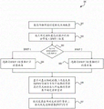
Fig. 4 illustrates a flow diagram of an example process 400 for determining resources from different sets of resources configured for different DM-RS mapping types, in accordance with one or more embodiments. For purposes of illustration, the process 400 is described herein primarily with reference to the receiver circuit 220 in the wireless communication device 200 of fig. 2. However, the process 400 is not limited to the receiver circuit 220 in the wireless communication device 200 of fig. 2, and one or more blocks (or operations) of the process 400 may be performed by one or more other components or chips in the wireless communication device 200. The wireless communication device 200 is also denoted as an exemplary device and the operations described herein may be performed by any suitable device, such as one or more of the wireless communication devices 118-132. Further, for illustrative purposes, the blocks of process 400 are described herein as occurring serially or linearly. However, multiple blocks of process 400 may occur in parallel. Additionally, the blocks of process 400 need not be performed in the order shown, and/or one or more blocks of process 400 need not be performed and/or may be replaced by other operations.
Subsequently, when it is determined that the DM-RS mapping type is mapping type a, the station selects a resource set corresponding to the DM-RS mapping type a at step 404. At step 405, when it is determined that the DM-RS mapping type is mapping type B, the station selects a resource set corresponding to the DM-RS mapping type B. Next, at step 406, the station determines the actual resources from the selected set of resources. In some aspects, the station may perform the selection using an indication included in the second message received from the base station. In other aspects, the station may perform the selection based on an implicit mapping of other PHY channels or signals to one or more resources in the selected set of resources such that the unmapped resources may be derived. Subsequently, at step 407, the station causes its transceiver circuitry (e.g., 205) to receive PDSCH signals or transmit PUSCH signals, e.g., on the determined actual resources.
In this embodiment, different resource sets are configured for different DM-RS mapping types (e.g., PDSCH/PUSCH mapping types a and B). As depicted in fig. 4, a station may first select a set of resources corresponding to a DM-RS mapping type and then determine the actual resources for transmitting PHY channels or signals. N resources may be configured for PDSCH mapping type a and type B, respectively, if based on the determined DCI overhead. A total of 2N resources may be configured according to this embodiment. Indeed, this approach may double the number of candidate resources available for resource allocation scheduling without any additional PHY signaling overhead compared to conventional approaches (e.g. 4G LTE) and help achieve much greater flexibility in resource allocation scheduling than conventional approaches.
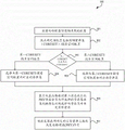
Fig. 5 depicts a flowchart of an example process 500 for determining resources from different sets of resources configured for different BWP configurations in accordance with one or more embodiments. For purposes of illustration, the process 500 is described herein primarily with reference to the receiver circuit 220 in the wireless communication device 200 of fig. 2. However, the process 500 is not limited to the receiver circuit 220 in the wireless communication device 200 of fig. 2, and one or more blocks (or operations) of the process 500 may be performed by one or more other components or chips in the wireless communication device 200. The wireless communication device 200 is also denoted as an exemplary device and the operations described herein may be performed by any suitable device, such as one or more of the wireless communication devices 118-132. Further, for illustrative purposes, the blocks of process 500 are described herein as occurring serially or linearly. However, multiple blocks of process 500 may occur in parallel. Additionally, the blocks of process 500 need not be performed in the order shown, and/or one or more blocks of process 500 need not be performed and/or may be replaced by other operations.
Subsequently, when it is determined that BWP is configured as BWP 1, the station selects a resource set corresponding to BWP 1 configuration at step 504. At step 505, upon determining that BWP is configured as BWP 2, the station selects a resource set corresponding to BWP 2 configuration. Next, at step 506, the site determines actual resources from the selected set of resources. In some aspects, the station may perform the selection using an indication included in the second message received from the base station. In other aspects, the station may perform the selection based on an implicit mapping of other PHY channels or signals to one or more resources in the selected set of resources such that the unmapped resources may be derived. Subsequently, at step 507, the station causes its transceiver circuitry (e.g., 205) to receive PDSCH signals or transmit PUSCH signals, e.g., on the determined actual resources.
In this embodiment, different resource sets are configured for different BWP configurations (e.g., BWP 1 and BWP 2). As depicted in fig. 5, a station may first select a set of resources corresponding to a particular BWP configuration and then determine the actual resources for transmitting a PHY channel or signal. N resources may be configured for BWP 1 and BWP 2, respectively, if based on the determined DCI overhead. Similarly, this approach may double the number of candidate resources available for resource allocation scheduling without any additional PHY signaling overhead and help achieve much greater flexibility in resource allocation scheduling than the conventional approach (e.g., 4G LTE) compared to the conventional approach.
Fig. 6 illustrates a flow diagram of an example process 600 for determining resources from different sets of resources configured for different component carrier configurations in accordance with one or more embodiments. For purposes of illustration, the process 600 is described herein primarily with reference to the receiver circuit 220 in the wireless communication device 200 of fig. 2. However, the process 600 is not limited to the receiver circuit 220 in the wireless communication device 200 of fig. 2, and one or more blocks (or operations) of the process 600 may be performed by one or more other components or chips in the wireless communication device 200. The wireless communication device 200 is also denoted as an exemplary device and the operations described herein may be performed by any suitable device, such as one or more of the wireless communication devices 118-132. Further, for illustrative purposes, the blocks of process 600 are described herein as occurring serially or linearly. However, multiple blocks of process 600 may occur in parallel. Additionally, the blocks of the process 600 need not be performed in the order shown, and/or one or more blocks of the process 600 need not be performed and/or may be replaced by other operations.
Subsequently, when it is determined that the component carrier configuration is CC 1, the station selects a resource set corresponding to the CC 1 configuration at step 604. At step 605, when it is determined that the component carrier configuration is CC 2, the station selects a resource set corresponding to the CC 2 configuration. Next, at step 606, the site determines actual resources from the selected set of resources. In some aspects, the station may perform the selection using an indication included in the second message received from the base station. In other aspects, the station may perform the selection based on an implicit mapping of other PHY channels or signals to one or more resources in the selected set of resources such that the unmapped resources may be derived. Subsequently, at step 607, the station has its transceiver circuitry (e.g., 205) to receive PDSCH signals or transmit PUSCH signals, e.g., on the determined actual resources.
In this embodiment, different resource sets are configured for different component carrier configurations (e.g., CC 1 and CC 2). As depicted in fig. 6, a station may first select a set of resources corresponding to a particular component carrier configuration and then determine the actual resources for transmitting PHY channels or signals. N resources may be configured for CC 1 and CC 2, respectively, if based on the determined DCI overhead. Similarly, this approach may double the number of candidate resources available for resource allocation scheduling without any additional PHY signaling overhead compared to the legacy approach (e.g., 4G LTE) and help achieve much greater flexibility in resource allocation scheduling than the legacy approach.
Fig. 7 illustrates a flow diagram of an example process 700 for determining resources from different sets of resources configured for different serving cell configurations in accordance with one or more embodiments. For purposes of illustration, the process 700 is described herein primarily with reference to the receiver circuit 220 in the wireless communication device 200 of fig. 2. However, the process 700 is not limited to the receiver circuit 220 in the wireless communication device 200 of fig. 2, and one or more blocks (or operations) of the process 700 may be performed by one or more other components or chips in the wireless communication device 200. The wireless communication device 200 is also denoted as an exemplary device and the operations described herein may be performed by any suitable device, such as one or more of the wireless communication devices 118-132. Further, for illustrative purposes, the blocks of process 700 are described herein as occurring serially or linearly. However, multiple blocks of process 700 may occur in parallel. Additionally, the blocks of process 700 need not be performed in the order shown, and/or one or more blocks of process 700 need not be performed and/or may be replaced by other operations.
Process 700 begins at step 701, where a station (e.g., 128, 200) obtains a configuration associated with a PHY channel. Next, at step 702, the station determines that the configuration includes a serving cell configuration by receiving a message from a base station (e.g., 116) indicating that the received frame includes a serving cell configuration for resource allocation scheduling. In some aspects, the received frame is a downlink frame associated with a downlink transmission of a base station. The received frame may include PHY channels/signals (e.g., PDSCH, PDCCH). In some embodiments, the serving cell configuration is associated with a resource allocation schedule for downlink transmissions. Next, at step 703, the station determines whether the serving cell configuration is a first serving cell configuration (abbreviated as "SCELL 1") or a second serving cell configuration (abbreviated as "SCELL 2"). If the serving cell configuration is SCELL 1, then process 700 proceeds to step 704. Otherwise, process 700 proceeds to step 705.
Subsequently, when it is determined that the serving cell configuration is SCELL 1, the station selects a resource set corresponding to the SCELL 1 configuration at step 704. At step 705, upon determining that the serving cell configuration is SCELL 2, the station selects a resource set corresponding to the SCELL 2 configuration. Next, at step 706, the site determines actual resources from the selected set of resources. In some aspects, the station may perform the selection using an indication included in the second message received from the base station. In other aspects, the station may perform the selection based on an implicit mapping of other PHY channels or signals to one or more resources in the selected set of resources such that the unmapped resources may be derived. Subsequently, at step 707, the station causes its transceiver circuitry (e.g., 205) to receive PDSCH signals or transmit PUSCH signals, e.g., on the determined actual resources.
In this embodiment, different resource sets are configured for different serving cell configurations (e.g., SCELL 1 and SCELL 2). As depicted in fig. 7, a station may first select a set of resources corresponding to a particular serving cell configuration and then determine the actual resources for transmission of PHY channels or signals. N resources may be configured for SCELL 1 and SCELL 2, respectively, if based on the determined DCI overhead. Similarly, this approach may double the number of candidate resources available for resource allocation scheduling without any additional PHY signaling overhead and help achieve much greater flexibility in resource allocation scheduling than the legacy approach (e.g., 4G LTE) compared to the legacy approach.
Fig. 8 illustrates a flow diagram of an example process 800 for determining resources from different sets of resources configured for different transmission waveforms or multiple access configurations in accordance with one or more embodiments. For purposes of illustration, the process 800 is described herein primarily with reference to the receiver circuit 220 in the wireless communication device 200 of fig. 2. However, the process 800 is not limited to the receiver circuit 220 in the wireless communication device 200 of fig. 2, and one or more blocks (or operations) of the process 800 may be performed by one or more other components or chips in the wireless communication device 200. Wireless communication device 200 is also denoted as an exemplary device and the operations described herein may be performed by any suitable device, such as one or more of wireless communication devices 118-132. Further, for illustrative purposes, the blocks of process 800 are described herein as occurring serially or linearly. However, multiple blocks of process 800 may occur in parallel. Additionally, the blocks of the process 800 need not be performed in the order shown, and/or one or more blocks of the process 800 need not be performed and/or may be replaced by other operations.
Subsequently, when it is determined that transform precoding is used in uplink transmission, the station selects a resource set corresponding to the uplink transmission using transform precoding at step 804. At step 805, when it is determined that transform precoding is not used in uplink transmission, the station selects a set of resources corresponding to uplink transmission that does not include transform precoding. Next, at step 806, the station determines actual resources from the selected set of resources. In some aspects, the station may perform the selection using an indication included in the second message received from the base station. In other aspects, the station may perform the selection based on an implicit mapping of other PHY channels or signals to one or more resources in the selected set of resources such that the unmapped resources may be derived. Then, at step 807, the station causes its transceiver circuitry (e.g., 205) to receive PDSCH signals or transmit PUSCH signals, e.g., on the determined actual resources.
In this embodiment, different sets of resources are configured for different transmission waveforms or multiple access schemes (e.g., whether or not transform precoding is used in uplink transmission). As depicted in fig. 8, a station may first select a set of resources corresponding to uplink transmissions that use transform precoding (e.g., DFT-s-OFDM) or uplink transmissions that do not use transform precoding (e.g., CP-OFDM), and then determine the actual resources for transmission of a PHY channel or signal. The N resources may be configured for uplink transmission using transform precoding or uplink transmission not using transform precoding, respectively, if based on the determined DCI overhead. Similarly, this approach may double the number of candidate resources available for resource allocation scheduling without any additional PHY signaling overhead and facilitate much greater flexibility in resource allocation scheduling than the legacy approach (e.g., 4G LTE) compared to the legacy approach.
Fig. 9 illustrates a flow diagram of an example process 900 for determining resources from different sets of resources configured for different CORESET/search space configurations in accordance with one or more embodiments. For purposes of illustration, the process 900 is described herein primarily with reference to the receiver circuit 220 in the wireless communication device 200 of fig. 2. However, the process 900 is not limited to the receiver circuit 220 in the wireless communication device 200 of fig. 2, and one or more blocks (or operations) of the process 900 may be performed by one or more other components or chips in the wireless communication device 200. The wireless communication device 200 is also denoted as an exemplary device and the operations described herein may be performed by any suitable device, such as one or more of the wireless communication devices 118-132. Further, for illustrative purposes, the blocks of process 900 are described herein as occurring serially or linearly. However, multiple blocks of process 900 may occur in parallel. Additionally, the blocks of the process 900 need not be performed in the order shown, and/or one or more blocks of the process 900 need not be performed and/or may be replaced by other operations.
Subsequently, when it is determined that the received frame is configured with a first CORESET/search space configuration, the station selects a set of resources corresponding to the first CORESET/search space configuration at step 904. At step 905, i.e., when it is determined that the received frame is configured with a second CORESET/search space configuration, the station selects a set of resources corresponding to the second CORESET/search space configuration. Next, at step 906, the station determines the actual resources from the selected set of resources. In some aspects, the station may perform the selection using an indication included in the second message received from the base station. In other aspects, the station may perform the selection based on an implicit mapping of other PHY channels or signals to one or more resources in the selected set of resources such that the unmapped resources may be derived. Subsequently, at step 907, the station causes its transceiver circuitry (e.g., 205) to receive PDSCH signals or transmit PUSCH signals, e.g., on the determined actual resources.
In this embodiment, different resource sets are configured for different CORESET/search space configurations (e.g., their periodic configuration and/or temporal location). As depicted in fig. 9, a station may first select a set of resources corresponding to a particular CORESET/search space configuration and then determine the actual resources for transmission of a PHY channel or signal. N resources may be configured for the first and second CORESET/search space configurations, respectively, if based on the determined DCI overhead. Similarly, this approach may double the number of candidate resources available for resource allocation scheduling without any additional PHY signaling overhead and help achieve much greater flexibility in resource allocation scheduling than the legacy approach (e.g., 4G LTE) compared to the legacy approach.
Figure 10 conceptually illustrates an electronic system 1000 that may be used to implement one or more embodiments of the present technology. For example, electronic system 1000 may be a network device, a media converter, a desktop computer, a laptop computer, a tablet computer, a server, a switch, a router, a base station, a receiver, a telephone, or any general electronic device that transmits signals over a network. Such an electronic system 1000 includes interfaces for various types of computer-readable media, as well as various other types of computer-readable media. In one or more embodiments, electronic system 1000 is or includes one or more of wireless communication devices 118-132. Electronic system 1000 includes a bus 1008, one or more processors 1012, a system memory 1004, a Read Only Memory (ROM) 1010, a persistent storage 1002, an input device interface 1014, an output device interface 1006, and a network interface 1016, or subsets and variations thereof.
Bus 1008 generally represents all of the system bus, peripheral buses, and chipset buses that communicatively connect the numerous internal devices of electronic system 1000. In one or more embodiments, the bus 1008 communicatively connects the one or more processors 1012 to the ROM 1010, the system memory 1004, and the permanent storage device 1002. One or more processors 1012 retrieve instructions to be executed and data to be processed from these various storage units to perform the processes of the present disclosure. In various embodiments, one or more of processors 1012 may be a single processor or a multi-core processor.
The ROM 1010 stores static data and instructions for the one or more processors 1012 and other modules of the electronic system. On the other hand, the persistent storage device 1002 is a read-write memory device. The persistent storage device 1002 is a non-volatile storage unit that stores instructions and data even when the electronic system 1000 is turned off. One or more embodiments of the present disclosure use a mass storage device (e.g., a magnetic or optical disk and its corresponding disk drive) as the persistent storage device 1002.
Other embodiments use removable storage devices (e.g., floppy disks, flash drives, and their corresponding disk drives) as the permanent storage device 1002. Like the persistent storage device 1002, the system memory 1004 is a read-write memory device. However, unlike the persistent storage device 1002, the system memory 1004 is a volatile read-and-write memory, such as random access memory. The system memory 1004 stores any instructions and data required by the one or more processors 1012 to operate. In one or more embodiments, the processes of the present disclosure are stored in the system memory 1004, permanent storage 1002, and/or ROM 1010. From these various storage units, one or more processors 1012 retrieve the instructions to be executed and the data to be processed in order to perform the processes of one or more embodiments.
The bus 1008 also connects to an input device interface 1014 and an output device interface 1006. The input device interface 1014 enables a user to communicate information and select commands to the electronic system. Input devices used with input device interface 1014 include, for example, alphanumeric keyboards and pointing devices (also referred to as "cursor control devices"). Output device interface 1006 enables, for example, the display of images generated by electronic system 1000. Output devices used with output device interface 1006 include, for example, printers and display devices such as Liquid Crystal Displays (LCDs), light Emitting Diode (LED) displays, organic Light Emitting Diode (OLED) displays, flexible displays, flat panel displays, solid state displays, projectors, or any other device for outputting information. Included in one or more embodiments are devices that function as both input and output devices, such as a touch screen. In these embodiments, the feedback provided to the user may be any form of sensory feedback, such as visual feedback, auditory feedback, or tactile feedback, and input from the user may be received in any form, including acoustic, speech, or tactile input.
Finally, as shown in FIG. 10, bus 1008 also couples electronic system 1000 to one or more networks (not shown) through one or more network interfaces 1016. In this manner, the computer may be part of one or more computer networks, such as a local area network ("LAN"), a wide area network ("WAN"), or an intranet or network of networks, such as the internet. Any or all of the components of the electronic system 1000 may be used in combination with the present disclosure.
For convenience, various examples of aspects of the disclosure are described below as entries. These are provided as examples only and do not limit the present technology.
Entry A1: a station for facilitating wireless communication in a broadband cellular network, the station comprising: one or more memories; and one or more processors coupled with the one or more memories, the one or more processors configured to cause: determining a first resource configuration of a plurality of resource configurations in at least one of a plurality of domains associated with a physical layer (PHY) channel or signal, wherein each domain of the plurality of domains corresponds to one of: demodulation reference signal mapping type, partial bandwidth configuration, component carrier in carrier aggregation, serving cell, transformation precoding for uplink transmission or control resource set/search space configuration; selecting a first set of resources corresponding to a first resource configuration; determining an actual resource from a plurality of resources in the selected first set of resources; and occupying the determined actual resources to transmit or receive a corresponding PHY channel or signal.
Entry A2: a station for facilitating wireless communication in a broadband cellular network, the station comprising: a transceiver; one or more memories; and one or more processors coupled with the one or more memories, the one or more processors configured to cause: obtaining a configuration associated with a physical layer (PHY) channel; selecting a set of resources from a plurality of resources corresponding to the configuration; determining actual resources from the selected set of resources; and causing the transceiver to transmit or receive the corresponding PHY signal on the determined actual resource.
Entry B1: a method, comprising: determining whether a physical layer (PHY) channel or signal includes a first resource configuration of a plurality of resource configurations or a second resource configuration of the plurality of resource configurations in one of a plurality of domains, wherein each domain of the plurality of domains corresponds to one of: demodulation reference signal (DM-RS) mapping type, partial bandwidth configuration, component carrier in carrier aggregation, serving cell, transform precoding for uplink transmission or control resource set (CORESET)/search space configuration; selecting a first set of resources corresponding to the first resource configuration when the PHY channel or signal includes the first resource configuration; selecting a second set of resources corresponding to the second resource configuration when the PHY channel or signal includes the second resource configuration; determining an actual resource from a plurality of resources in the selected first set of resources or the selected second set of resources; and occupying the determined actual resources to transmit or receive a corresponding PHY channel or signal.
Entry B2: a method, comprising: obtaining a configuration associated with a physical layer (PHY) channel; selecting a set of resources from a plurality of resources corresponding to the configuration; determining actual resources from the selected set of resources or the selected second set of resources; and causing the transceiver to transmit or receive the corresponding PHY signal on the determined actual resource.
Entry C1: a non-transitory computer-readable storage medium storing computer-executable instructions that, when executed by one or more processors, cause the one or more processors to perform operations comprising: determining a first resource configuration of a plurality of resource configurations in at least one of a plurality of domains associated with a physical layer (PHY) channel or signal, wherein each domain of the plurality of domains corresponds to one of: demodulation reference signal mapping type, partial bandwidth configuration, component carrier in carrier aggregation, serving cell, transformation precoding for uplink transmission or control resource set/search space configuration; selecting a first set of resources corresponding to a first resource configuration; determining an actual resource from a plurality of resources in the selected first set of resources; and occupying the determined actual resources to transmit or receive a corresponding PHY channel or signal.
Entry C2: a non-transitory computer-readable storage medium storing computer-executable instructions that, when executed by one or more processors, cause the one or more processors to perform operations comprising: obtaining a configuration associated with a physical layer (PHY) channel; selecting a set of resources from a plurality of resources corresponding to the configuration; determining actual resources from the selected set of resources; and causing the transceiver to transmit or receive the corresponding PHY signal on the determined actual resource.
Examples of attaching items in one or more aspects are described below.
Entry A1: the one or more processors are configured to cause: a first message received from a base station is processed, wherein a first set of resources is selected based on an indication included in the first message.
Entry A2: the one or more processors are configured to cause: processing a second message received from the base station, wherein the actual resources are determined based on including an indication in the second message, and wherein the second message follows the first message.
Entry A3: the one or more processors are configured to cause: processing a first message received from a base station; and acquiring predetermined control information on one or more of: a demodulation reference signal (DM-RS) mapping type, a partial Bandwidth (BWP) configuration, a Component Carrier (CC), a serving cell, a transmission waveform, or a multiple access scheme, wherein the first set of resources is selected based on an indication included in the first message and predetermined control information acquired from the first message, and wherein the first message is received before the first message.
Entry A4: selecting a first set of resources based on predetermined control information regarding one or more of: demodulation reference signal (DM-RS) mapping type, partial Bandwidth (BWP) configuration, component Carrier (CC), serving cell, use of transform precoding in Uplink (UL) transmission.
Entry A5: the actual resources are determined based on an implicit mapping between the resources in the selected first set of resources and one or more other PHY channels or signals.
Entry A6: the PHY channels include: a physical Downlink (DL) shared channel (PDSCH), a physical Uplink (UL) shared channel (PUSCH), a Physical DL Control Channel (PDCCH), a Physical UL Control Channel (PUCCH), a Physical Random Access Channel (PRACH), wherein the PHY signal corresponds to a channel state information reference signal (CSI-RS), a Scheduling Request (SR), or a Sounding Reference Signal (SRs).
Entry A7: each of the plurality of resource configurations corresponds to a different one of a plurality of demodulation reference signal (DM-RS) mapping types for a DL PHY channel or an UL PHY channel.
Entry A8: each of the plurality of resource configurations corresponds to a different one of a plurality of partial Bandwidth (BWP) configurations.
Entry A9: each of the plurality of resource configurations corresponds to a different Component Carrier (CC) of a plurality of CCs in the carrier aggregation.
Entry a10: each of the plurality of resource configurations corresponds to a different serving cell of the plurality of serving cells.
Entry a11: when transform precoding is used in uplink transmission, each of the plurality of resource configurations corresponds to a different one of the plurality of transmission waveforms.
Entry a12: when using transform precoding in uplink transmission, each of the plurality of resource configurations corresponds to a different one of multiple access schemes.
Item A13: each of the plurality of resource configurations corresponds to a different Physical Downlink Control Channel (PDCCH) configuration of a plurality of PDCCH configurations.
Entry a14: configurations associated with PHY channels include: a demodulation reference signal (DM-RS) mapping type, a fractional Bandwidth (BWP) configuration, a component carrier, a serving cell, a transmission waveform, a multiple access scheme, or a Physical Downlink Control Channel (PDCCH) configuration.
Entry a15: the transceiver is configured to receive a first message from a base station, wherein a configuration is obtained from the first message.
Entry a16: the transceiver is configured to receive a second message from the base station, and wherein the actual resources are determined based on an indication included in the second message.
Entry a17: different configurations correspond to different sets of resources.
Entry a18: configuring a plurality of resource sets for the PHY channel, and wherein different configurations correspond to different resource sets comprising: each DM-RS mapping type corresponds to each resource set; or each BWP configuration corresponds to each resource set; or each component carrier corresponds to each resource set; or each serving cell corresponds to each resource set; or each transmission waveform corresponds to each resource set; or each of the multiple access schemes corresponds to each resource set; or each PDCCH configuration corresponds to each resource set.
Entry B1: one of the plurality of domains includes a demodulation reference signal (DM-RS) mapping type, and wherein the first resource configuration corresponds to a Physical Downlink Shared Channel (PDSCH)/Physical Uplink Shared Channel (PUSCH) mapping type a and the second resource configuration corresponds to a PDSCH/PUSCH mapping type B.
Entry B2: one of the plurality of domains corresponds to a partial Bandwidth (BWP), and wherein the first resource configuration corresponds to a first BWP configuration and the second resource configuration corresponds to a second BWP configuration.
Entry B3: one of the plurality of domains corresponds to a component carrier in carrier aggregation for a PHY channel or signal, and wherein the first resource configuration corresponds to a first component carrier and the second resource configuration corresponds to a second component carrier.
Entry B4: one of the plurality of domains corresponds to a serving cell for a PHY channel or signal, and wherein the first resource configuration corresponds to a first serving cell and the second resource configuration corresponds to a second serving cell.
Entry B5: one of the plurality of domains corresponds to transform precoding in the uplink transmission, and wherein the first resource configuration corresponds to a first transmission waveform for the uplink transmission with transform precoding and the second resource configuration corresponds to a second transmission waveform for the uplink transmission without transform precoding.
Entry B6: one of the plurality of domains corresponds to a control resource set (CORESET)/search space configuration, wherein a first resource configuration corresponds to a first CORESET/search space configuration and a second resource configuration corresponds to a second CORESET/search space configuration.
Entry B7: configurations associated with PHY channels include: a demodulation reference signal (DM-RS) mapping type, a fractional Bandwidth (BWP) configuration, a component carrier, a serving cell, a transmission waveform, a multiple access scheme, or a Physical Downlink Control Channel (PDCCH) configuration.
Entry B8: the transceiver is configured to receive a first message from a base station, and wherein the configuration is obtained from the first message.
Entry B9: the transceiver is configured to receive a second message from the base station, and wherein the actual resources are determined based on an indication included in the second message.
Entry B10: different configurations correspond to different sets of resources.
Entry B11: multiple resource sets are configured for the PHY channel, and wherein different configurations correspond to different resource sets including: each DM-RS mapping type corresponds to each resource set; or each BWP configuration corresponds to each resource set; or each component carrier corresponds to each resource set; or each serving cell corresponds to each resource set; or each transmission waveform corresponds to each resource set; or each of the multiple access schemes corresponds to each resource set; or each PDCCH configuration corresponds to each resource set.
Entry C1: the operation comprises the following steps: radio Resource Control (RRC) signaling included in a downlink frame received from a base station is acquired, wherein a first resource configuration and a first resource set are determined from the acquired RRC signaling.
Entry C2: the operation comprises the following steps: downlink Control Information (DCI) included in the downlink frame is acquired, wherein the DCI indicates an index corresponding to an actual resource in the selected first set of resources.
Entry C3: configurations associated with PHY channels include: a demodulation reference signal (DM-RS) mapping type, a fractional Bandwidth (BWP) configuration, a component carrier, a serving cell, a transmission waveform, a multiple access scheme, or a Physical Downlink Control Channel (PDCCH) configuration.
Entry C4: the transceiver is configured to receive a first message from a base station, and wherein the configuration is obtained from the first message.
Entry C5: the transceiver is configured to receive a second message from the base station, and wherein the actual resources are determined based on an indication included in the second message.
Entry C6: different configurations correspond to different sets of resources.
Entry C7: configuring a plurality of resource sets for the PHY channel, and wherein different configurations correspond to different resource sets comprising: each DM-RS mapping type corresponds to each resource set; or each BWP configuration corresponds to each resource set; or each component carrier corresponds to each resource set; or each serving cell corresponds to each resource set; or each transmission waveform corresponds to each resource set; or each of the multiple access schemes corresponds to each resource set; or each PDCCH configuration corresponds to each resource set.
A method comprising one or more of the methods, operations, or portions thereof described herein.
An apparatus comprising means adapted to perform one or more of the methods, operations, or portions thereof described herein.
A hardware device comprising circuitry configured to perform one or more of the methods, operations, or portions thereof described herein.
An apparatus comprising means adapted for performing one or more of the methods, operations, or portions thereof described herein.
An apparatus comprising components operable to perform one or more of the methods, operations, or portions thereof described herein.
In one aspect, a method may be an operation, an instruction, or a function, and vice versa. In one aspect, an entry may be modified to include some or all of the terms (e.g., instructions, operations, functions, or components) recited in other entry(s), word(s), sentence(s), phrase(s), paragraph(s), and/or claim(s). During prosecution, one or more claims may be amended as dependent on one or more other claims and one or more claims may be amended to delete one or more features.
Implementations within the scope of the present disclosure may be implemented, in part or in whole, using a tangible computer-readable storage medium (or multiple tangible computer-readable storage media of one or more types) encoding one or more instructions. The tangible computer readable storage medium may also be non-transitory in nature.
A computer-readable storage medium may be any storage medium that can be read, written, or otherwise accessed by a general purpose or special purpose computing device, including any processing electronics and/or processing circuitry capable of executing instructions. The computer readable medium may include, by way of example and not limitation, any volatile semiconductor memory. The computer readable medium may also include any non-volatile semiconductor memory.
Additionally, the computer-readable storage medium may include any non-semiconductor memory, such as optical disk storage, magnetic tape, other magnetic storage devices, or any other medium capable of storing one or more instructions. In some implementations, the tangible computer-readable storage medium may be directly coupled to the computing device, while in other implementations, the tangible computer-readable storage medium may be indirectly coupled with the computing device, e.g., via one or more wired connections, one or more wireless connections, or any combination thereof.
The instructions may be directly executable or may be used to develop executable instructions. For example, the instructions may be implemented as executable or non-executable machine code, or as instructions in a high-level language, which may be compiled to produce executable or non-executable machine code. Further, instructions may also be implemented as or may include data. Computer-executable instructions may also be organized in any format, including routines, subroutines, programs, data structures, objects, modules, applications, applets, functions, and the like. Those skilled in the art will appreciate that the details including, but not limited to, the number, structure, order, and organization of instructions may vary considerably without altering the underlying logic, functionality, processing, and output.
Although the above discussion primarily refers to a microprocessor or multi-core processor executing software, one or more implementations are performed by one or more integrated circuits, such as an Application Specific Integrated Circuit (ASIC) or Field Programmable Gate Array (FPGA). In one or more embodiments, such integrated circuits execute instructions stored on the circuit itself.
Those skilled in the art will appreciate that the various illustrative blocks, modules, elements, components, methods, and algorithms described herein may be implemented as electronic hardware, computer software, or combinations of both. To illustrate this interchangeability of hardware and software, various illustrative blocks, modules, elements, components, methods, and algorithms have been described above generally in terms of their functionality. Whether such functionality is implemented as hardware or software depends upon the particular application and design constraints imposed on the overall system. Skilled artisans may implement the described functionality in varying ways for each particular application. The various components and blocks may be arranged differently (e.g., arranged in a different order or divided in a different manner) without departing from the scope of the present technology.
It should be understood that any particular order or hierarchy of blocks in the processes disclosed is an illustration of example methodologies. It should be understood that the particular order or hierarchy of blocks in the process may be rearranged or all illustrated blocks may be performed based on design preferences. Any of the blocks may be performed simultaneously. In one or more embodiments, multitasking and parallel processing may be advantageous. Moreover, the separation of various system components in the embodiments described above should not be understood as requiring such separation in all embodiments, and it should be understood that the described program components and systems can generally be integrated within a single software product or packaged into multiple software products.
As used in the description and any claims of this application, the terms "base station," "receiver," "transmitter," "computer," "server," "processor," and "memory" all refer to electronic or other technical devices. These terms do not include one or a group of people. For purposes of this description, the term "display" or "displaying" refers to displaying on an electronic device.
As used herein, the phrase "at least one of," separating any item by the terms "and" or "preceding a series of items is modifying the entire list, rather than modifying each member (e.g., each item) of an item. The phrase "at least one" does not require the selection of at least one of each of the listed items; rather, the phrase is intended to include at least one of any term, and/or at least one of any combination of terms, and/or at least one of each term. For example, the phrases "at least one of A, B and C" or "at least one of A, B or C" each refer to: only A, only B or only C; A. any combination of B and C; and/or A, B and C.
The terms "configured to," "operable to," and "programmed to" do not imply any particular tangible or intangible modification of an object, but are intended to be used interchangeably. In one or more embodiments, the processor is configured to monitor and control operations or components, which also means that the processor is programmed to monitor and control operations or the processor is operable to monitor and control operations. Likewise, the processor is configured to execute code, which may be interpreted as the processor being programmed to execute code or the processor being operable to execute code.
Phrases such as an aspect, the aspect, another aspect, some aspects, one or more aspects, an implementation, the implementation, another implementation, some implementations, one or more implementations, an embodiment, the embodiment, another embodiment, some embodiments, one or more embodiments, a configuration, the configuration, another configuration, some configurations, one or more configurations, the technology, the disclosure, the present application, and other variations of these are for convenience and do not imply that a disclosure relating to such phrase is essential to the technology or that such disclosure applies to all configurations of the technology. Disclosure relating to such phrases may apply to all configurations, or one or more configurations. Disclosure relating to such phrases may provide one or more examples. Phrases such as one aspect or certain aspects may refer to one or more aspects and vice versa, and this applies analogously to other preceding phrases.
The word "exemplary" is used herein to mean "serving as an example, instance, or illustration. Any embodiment described herein as "exemplary" or "exemplary" is not necessarily to be construed as preferred or advantageous over other embodiments. Furthermore, to the extent that the terms "including", "having", and the like are used in either the detailed description or the claims, such terms are intended to be inclusive in a manner similar to the term "comprising" as "comprising" is interpreted when employed as a transitional word in a claim.
All structural and functional equivalents to the elements of the various aspects described throughout this disclosure that are known or later come to be known to those of ordinary skill in the art are expressly incorporated herein by reference and are intended to be encompassed by the claims. Furthermore, nothing disclosed herein is intended to be dedicated to the public regardless of whether such disclosure is explicitly recited in the claims. No claim element should be construed in accordance with the provisions of 35 u.s.c. § 112 sixth paragraph unless the element is explicitly recited using the phrase "means for.
The above description is provided to enable any person skilled in the art to practice the various aspects described herein. Various modifications to these aspects will be readily apparent to those skilled in the art, and the generic principles defined herein may be applied to other aspects. Thus, the claims are not intended to be limited to the aspects shown herein, but is to be accorded the full scope consistent with the language claims, wherein reference to an element in the singular is not intended to mean "one and only one" unless specifically so stated, but rather "one or more. The term "some" means one or more unless specifically stated otherwise. Pronouns in the male (e.g., his) include the female and the neutral gender (e.g., her and it), and vice versa. Headings and sub-headings, if any, are used for convenience only and do not limit the disclosure.
Claims (7)
1. A station for wireless communication, the station comprising:
a transceiver;
one or more memories; and
one or more processors coupled with the one or more memories, the one or more processors configured to cause:
obtaining a configuration associated with a physical layer (PHY) channel, wherein the PHY channel is configured with a plurality of resource sets, and wherein different configurations correspond to different resource sets; wherein, the two different resource sets means that the second resource set does not include at least one resource in the first resource set, one resource has a plurality of parameters in a time domain, a frequency domain, a code domain and a spatial domain, and the two different resource sets means that the value of the at least one parameter for the two resources is different;
selecting a set of resources corresponding to the configuration from a plurality of resources,
determining the actual resources from the selected set of resources, an
Causing the transceiver to transmit or receive a corresponding PHY signal on the determined actual resource;
wherein the configuration associated with the PHY channel comprises: a partial bandwidth BWP configuration;
wherein the transceiver is configured to receive a first message, and wherein the configuration is obtained from the first message; the transceiver is configured to receive a second message, and wherein the actual resource is determined based on an indication included in the second message.
2. The station of claim 1, wherein different configurations correspond to different sets of resources, including:
each of the BWP configurations corresponds to each resource set.
3. The station of claim 1, wherein the PHY channel comprises: a physical Downlink (DL) shared channel (PDSCH), a physical Uplink (UL) shared channel (PUSCH), a Physical DL Control Channel (PDCCH), a Physical UL Control Channel (PUCCH) and a Physical Random Access Channel (PRACH).
4. A method of wireless communication, comprising:
obtaining a configuration associated with a physical layer (PHY) channel; wherein a plurality of resource sets are configured for the PHY channel, and wherein different configurations correspond to different resource sets; wherein, the two different resource sets means that the second resource set does not include at least one resource in the first resource set, one resource has a plurality of parameters in a time domain, a frequency domain, a code domain and a spatial domain, and the two different resource sets means that the value of the at least one parameter for the two resources is different;
selecting a set of resources from a plurality of resources corresponding to the configuration;
determining actual resources from the selected set of resources; and
transmitting or receiving a corresponding PHY signal on the determined actual resource;
wherein the configuration associated with the PHY channel comprises: a partial bandwidth BWP configuration;
receiving a first message, wherein the configuration is obtained according to the first message;
receiving a second message, wherein the actual resource is determined based on an indication included in the second message.
5. The method of claim 4, wherein different configurations correspond to different sets of resources, comprising:
each of the BWP configurations corresponds to each resource set.
6. The method of claim 5, wherein the PHY channel comprises: a physical Downlink (DL) shared channel PDSCH, a physical Uplink (UL) shared channel PUSCH, a physical DL control channel PDCCH, a physical UL control channel PUCCH and a physical random access channel PRACH.
7. A non-transitory computer-readable storage medium storing computer-executable instructions that, when executed by one or more processors, cause the one or more processors to perform the method of one of claims 4 to 6.
Applications Claiming Priority (4)
| Application Number | Priority Date | Filing Date | Title |
|---|---|---|---|
| US201762594107P | 2017-12-04 | 2017-12-04 | |
| US62/594,107 | 2017-12-04 | ||
| CN201880065850.6A CN111201761A (en) | 2017-12-04 | 2018-12-04 | Multi-resource set configuration |
| PCT/CN2018/119232 WO2019109921A1 (en) | 2017-12-04 | 2018-12-04 | Multiple resource set configuration |
Related Parent Applications (1)
| Application Number | Title | Priority Date | Filing Date |
|---|---|---|---|
| CN201880065850.6A Division CN111201761A (en) | 2017-12-04 | 2018-12-04 | Multi-resource set configuration |
Publications (2)
| Publication Number | Publication Date |
|---|---|
| CN111641578A CN111641578A (en) | 2020-09-08 |
| CN111641578B true CN111641578B (en) | 2023-01-24 |
Family
ID=66751296
Family Applications (2)
| Application Number | Title | Priority Date | Filing Date |
|---|---|---|---|
| CN202010424068.8A Active CN111641578B (en) | 2017-12-04 | 2018-12-04 | Wireless communication method, station and storage medium |
| CN201880065850.6A Pending CN111201761A (en) | 2017-12-04 | 2018-12-04 | Multi-resource set configuration |
Family Applications After (1)
| Application Number | Title | Priority Date | Filing Date |
|---|---|---|---|
| CN201880065850.6A Pending CN111201761A (en) | 2017-12-04 | 2018-12-04 | Multi-resource set configuration |
Country Status (7)
| Country | Link |
|---|---|
| US (1) | US11246127B2 (en) |
| EP (1) | EP3718277B1 (en) |
| JP (1) | JP2021506155A (en) |
| KR (1) | KR20200091449A (en) |
| CN (2) | CN111641578B (en) |
| AU (1) | AU2018381739A1 (en) |
| WO (1) | WO2019109921A1 (en) |
Families Citing this family (5)
| Publication number | Priority date | Publication date | Assignee | Title |
|---|---|---|---|---|
| US11595236B2 (en) | 2019-08-16 | 2023-02-28 | Qualcomm Incorporated | Techniques for demodulation reference signal time domain pattern configuration |
| WO2021189213A1 (en) * | 2020-03-23 | 2021-09-30 | 华为技术有限公司 | Control information sending and receiving methods and apparatus |
| US11877292B2 (en) * | 2020-07-29 | 2024-01-16 | Qualcomm Incorporated | Techniques for activating and releasing resources across multiple component carriers |
| WO2022027485A1 (en) * | 2020-08-06 | 2022-02-10 | Nec Corporation | Methods for communication, terminal device, network device and computer-readable media |
| CN116235612A (en) * | 2020-10-09 | 2023-06-06 | 中兴通讯股份有限公司 | Resource mapping for scheduling inter-cell multi-transmission/reception point operation |
Family Cites Families (8)
| Publication number | Priority date | Publication date | Assignee | Title |
|---|---|---|---|---|
| US9215058B2 (en) | 2012-03-06 | 2015-12-15 | Blackberry Limited | Enhanced PHICH transmission for LTE-advanced |
| CN103581094B (en) * | 2012-07-24 | 2016-12-28 | 电信科学技术研究院 | The transmission method of downlink user dedicated demodulation reference signal and equipment |
| EP2882121B1 (en) * | 2012-07-30 | 2019-10-09 | Sharp Kabushiki Kaisha | Base station device, mobile station device, communication method, and integrated circuit |
| US9226211B2 (en) | 2013-01-17 | 2015-12-29 | Intel IP Corporation | Centralized partitioning of user devices in a heterogeneous wireless network |
| CN104009827B (en) * | 2013-02-22 | 2019-05-21 | 电信科学技术研究院 | A kind of transmission method and equipment of user equipment specific demodulated reference signal |
| CN107294682A (en) * | 2016-04-01 | 2017-10-24 | 中兴通讯股份有限公司 | DMRS sending method and device |
| EP3662711A4 (en) * | 2017-08-02 | 2021-02-17 | Intel IP Corporation | Apparatus, system and method to implement reserved resources for forward compatibility in new radio (nr) networks |
| US10666480B2 (en) * | 2017-11-16 | 2020-05-26 | Ofinno, Llc | Bandwidth part slot format indication |
-
2018
- 2018-12-04 AU AU2018381739A patent/AU2018381739A1/en not_active Abandoned
- 2018-12-04 EP EP18885826.0A patent/EP3718277B1/en active Active
- 2018-12-04 JP JP2020530360A patent/JP2021506155A/en not_active Withdrawn
- 2018-12-04 WO PCT/CN2018/119232 patent/WO2019109921A1/en unknown
- 2018-12-04 CN CN202010424068.8A patent/CN111641578B/en active Active
- 2018-12-04 CN CN201880065850.6A patent/CN111201761A/en active Pending
- 2018-12-04 KR KR1020207019359A patent/KR20200091449A/en not_active Application Discontinuation
-
2020
- 2020-05-27 US US16/884,924 patent/US11246127B2/en active Active
Also Published As
| Publication number | Publication date |
|---|---|
| KR20200091449A (en) | 2020-07-30 |
| EP3718277B1 (en) | 2022-06-22 |
| WO2019109921A1 (en) | 2019-06-13 |
| US20200288449A1 (en) | 2020-09-10 |
| US11246127B2 (en) | 2022-02-08 |
| CN111641578A (en) | 2020-09-08 |
| CN111201761A (en) | 2020-05-26 |
| EP3718277A1 (en) | 2020-10-07 |
| EP3718277A4 (en) | 2021-03-03 |
| JP2021506155A (en) | 2021-02-18 |
| AU2018381739A1 (en) | 2020-07-23 |
Similar Documents
| Publication | Publication Date | Title |
|---|---|---|
| CN111641578B (en) | Wireless communication method, station and storage medium | |
| US11832234B2 (en) | Scheduling in license assisted access | |
| US10367616B2 (en) | Dynamic sounding reference signal scheduling | |
| EP3155857B1 (en) | Channel usage beacon signal transmissions based on uplink transmissions over an unlicensed radio frequency spectrum band | |
| US11019584B2 (en) | User equipment operation in bandwidth narrower than synchronization signal bandwidth | |
| EP2826164B1 (en) | Down-sampling of cell-specific reference signals (crs) for a new carrier type (nct) | |
| US10555331B2 (en) | Nested system operation | |
| US20170279580A1 (en) | Sounding reference signal transmission for enhanced carrier aggregation | |
| EP3379760A1 (en) | Techniques for configuring uplink channels in unlicensed radio frequency spectrum bands | |
| US10341042B2 (en) | Narrowband operation with reduced sampling rate | |
| US10448380B2 (en) | Split symbol control for aligned numerology | |
| US11153052B2 (en) | Common reference signals for multiple search spaces within a control resource set | |
| KR20210042359A (en) | Method implemented by user equipment and user equipment | |
| US20220217705A1 (en) | Ue capability information for a unified tci framework | |
| WO2018228496A1 (en) | Indication method, processing method, and apparatus | |
| US11234264B2 (en) | Method and apparatus for uplink transmission in a wireless communication system | |
| WO2021226994A1 (en) | Control signaling for physical control channel reliability enhancement | |
| EP3857775A1 (en) | Burst detection in wireless communications | |
| WO2020155106A1 (en) | Wideband communications based on availability assessment | |
| US20200170006A1 (en) | Methods and devices for data communication based on license assisted access | |
| WO2017028000A1 (en) | Discovery signal transmission on unlicensed spectrum |
Legal Events
| Date | Code | Title | Description |
|---|---|---|---|
| PB01 | Publication | ||
| PB01 | Publication | ||
| SE01 | Entry into force of request for substantive examination | ||
| SE01 | Entry into force of request for substantive examination | ||
| GR01 | Patent grant | ||
| GR01 | Patent grant |