CN111629793B - Couplable fin device and toe body - Google Patents
Couplable fin device and toe body Download PDFInfo
- Publication number
- CN111629793B CN111629793B CN201880082526.5A CN201880082526A CN111629793B CN 111629793 B CN111629793 B CN 111629793B CN 201880082526 A CN201880082526 A CN 201880082526A CN 111629793 B CN111629793 B CN 111629793B
- Authority
- CN
- China
- Prior art keywords
- boot
- fin
- coupling
- connector
- toe
- Prior art date
- Legal status (The legal status is an assumption and is not a legal conclusion. Google has not performed a legal analysis and makes no representation as to the accuracy of the status listed.)
- Active
Links
Images


Classifications
-
- A—HUMAN NECESSITIES
- A63—SPORTS; GAMES; AMUSEMENTS
- A63B—APPARATUS FOR PHYSICAL TRAINING, GYMNASTICS, SWIMMING, CLIMBING, OR FENCING; BALL GAMES; TRAINING EQUIPMENT
- A63B31/00—Swimming aids
- A63B31/08—Swim fins, flippers or other swimming aids held by, or attachable to, the hands, arms, feet or legs
- A63B31/10—Swim fins, flippers or other swimming aids held by, or attachable to, the hands, arms, feet or legs held by, or attachable to, the hands or feet
- A63B31/11—Swim fins, flippers or other swimming aids held by, or attachable to, the hands, arms, feet or legs held by, or attachable to, the hands or feet attachable only to the feet
-
- A—HUMAN NECESSITIES
- A43—FOOTWEAR
- A43B—CHARACTERISTIC FEATURES OF FOOTWEAR; PARTS OF FOOTWEAR
- A43B5/00—Footwear for sporting purposes
- A43B5/08—Bathing shoes ; Aquatic sports shoes
-
- A—HUMAN NECESSITIES
- A43—FOOTWEAR
- A43C—FASTENINGS OR ATTACHMENTS OF FOOTWEAR; LACES IN GENERAL
- A43C11/00—Other fastenings specially adapted for shoes
-
- A—HUMAN NECESSITIES
- A43—FOOTWEAR
- A43C—FASTENINGS OR ATTACHMENTS OF FOOTWEAR; LACES IN GENERAL
- A43C11/00—Other fastenings specially adapted for shoes
- A43C11/14—Clamp fastenings, e.g. strap fastenings; Clamp-buckle fastenings; Fastenings with toggle levers
- A43C11/1406—Fastenings with toggle levers; Equipment therefor
- A43C11/142—Fastenings with toggle levers with adjustment means provided for on the shoe, e.g. rack
-
- A—HUMAN NECESSITIES
- A63—SPORTS; GAMES; AMUSEMENTS
- A63B—APPARATUS FOR PHYSICAL TRAINING, GYMNASTICS, SWIMMING, CLIMBING, OR FENCING; BALL GAMES; TRAINING EQUIPMENT
- A63B31/00—Swimming aids
- A63B31/08—Swim fins, flippers or other swimming aids held by, or attachable to, the hands, arms, feet or legs
- A63B31/10—Swim fins, flippers or other swimming aids held by, or attachable to, the hands, arms, feet or legs held by, or attachable to, the hands or feet
- A63B31/11—Swim fins, flippers or other swimming aids held by, or attachable to, the hands, arms, feet or legs held by, or attachable to, the hands or feet attachable only to the feet
- A63B2031/112—Swim fins, flippers or other swimming aids held by, or attachable to, the hands, arms, feet or legs held by, or attachable to, the hands or feet attachable only to the feet with means facilitating walking, e.g. rectractable, detachable or pivotable blades
Abstract
A method of coupling a boot toe body to a fin device involves moving a first boot connector in a direction toward a retaining surface while a portion of the boot toe body is between the first boot connector on the fin device and the retaining surface on the fin device, thereby retaining a portion of the boot toe body between the first boot connector and the retaining surface.
Description
Cross Reference to Related Applications
This application claims benefit and priority from U.S. patent application No. 15/789,747, filed on 20/10/2017 and published as U.S. patent publication No. 2018/0133555. U.S. provisional patent application 61/322,104, PCT international application number PCT/CA2011/000395, U.S. patent application number 13/639,446, PCT international application number PCT/CA2012/000946, U.S. patent application number 14/171,288, U.S. provisional patent application number 62/088,387, U.S. patent application number 14/435,084, PCT international application number PCT/CA2015/051278, U.S. provisional patent application number 62/281,890, U.S. provisional patent application number 62/412,603, PCT international application number PCT/CA2015/051278, PCT international application number PCT/CA2017/050044, U.S. patent application number 15/533,367, U.S. patent application number 15/666,206, and U.S. patent application number 15/789,747 are incorporated herein by reference in their entirety.
Technical Field
The present invention relates generally to fins, and more particularly to a fin device coupleable to a toe body, a toe body coupleable to a fin device, a system including a coupleable fin device and a toe body, and a method of coupling a fin device and a toe body.
Background
The user may couple known fins to each foot of the user. For example, the fins may help generate propulsion in the water when a user kicks the water in the water.
Many known fins have foot pockets for receiving the feet of the user, but such foot pockets are typically part of the fin and are available in only a few standard sizes, as the cost of manufacturing and distributing the entire fin with a wide variety of foot sizes, for example, can be very high. Thus, when a user selects such a fin, the user must also select the size of the individual foot pocket of the fin (usually from a small number of available sizes). Thus, such foot pockets do not generally conform to the user's foot and the space between the foot and the inner wall of the foot pocket may receive water, disadvantageously increasing the resistance of the fin in the water and limiting the user's control of the fin. Other known fins include a replacement for the foot pocket, but such known replacements may still require the user to select from a small number of standard sizes, as manufacturing and distribution costs may be high, for example, for a wide variety of foot sizes.
Disclosure of Invention
According to one embodiment, a method of coupling a boot-toe body to a fin device comprising a fin body coupled to a boot-coupling body is disclosed, the method comprising: connecting a first boot connector on a first end of the boot coupling to a first complementary boot connector on a top side of the toe body; and connecting a second boot connector on a second end of the boot coupling to a second complementary boot connector on the underside of the boot toe body.
According to another embodiment, a fin device coupleable to a toe body is disclosed, the device comprising: a fin body; and a boot coupling body coupleable to the fin body. The boot coupling body includes: first and second ends; a first boot connection means on a first end of the boot coupling (the first boot connection means for connecting with a first complementary boot connection means on a top side of the boot coupling); and a second boot connection means on the second end of the boot coupling body (the second boot connection means for connecting with a second complementary boot connection means on the underside of the toe body).
In accordance with another embodiment, a bootie body coupleable to a fin device is disclosed (the fin device including a fin body coupleable to a bootie coupling body including first and second ends), the bootie body including: a first boot connection means located on a top side of the toe body for connection with a first complementary boot connection means of the first end of the boot coupling; and a second boot connection means on the underside of the boot toe body (for connection with a second complementary boot connection means on the second end of the boot coupling).
According to an embodiment, a fin system is disclosed, the fin system comprising a device and a bootie body.
According to another embodiment, a fin device coupleable to a toe body is disclosed, the device comprising: a fin body; and a boot coupling body coupleable to the fin body. The boot coupling body includes: first and second ends; a first boot connector on a first end of the boot coupling (the first boot connector for connecting with a first complementary boot connector on a top side of the boot coupling); and a second boot connector on a second end of the boot coupling (the second boot connector for connecting with a second complementary boot connector on the underside of the toe body).
In accordance with another embodiment, a boot toe body coupleable to a fin device (the fin device coupleable to a fin body of a boot coupling body including first and second ends) is disclosed, the boot toe body comprising: a first boot connector on a top side of the boot toe body (for connection with a first complementary boot connector at a first end of the boot coupling body); and a second boot connector on the underside of the boot toe body (for connecting with a second complementary boot connector on the second end of the boot coupling).
According to another embodiment, a method of coupling a boot toe body to a fin device is disclosed, the method comprising, while a portion of the boot toe body is between a first boot connector on the fin device and a retaining surface on the fin device, moving the first boot connector in a direction toward the retaining surface, thereby maintaining the portion of the boot toe body between the first boot connector and the retaining surface.
According to another embodiment, a fin device connectable to a toe body is disclosed, the device comprising: a body defining a retaining surface; and a first boot connector movable in a direction toward and away from the fixed surface; wherein the fin device defines a space between a retaining surface on the fin device and the first boot connector for receiving a portion of the boot toe body in the space.
According to an embodiment, a fin system is disclosed, the fin system comprising a device and a bootie body.
Other aspects and features will become apparent to those ordinarily skilled in the art upon review of the following description of illustrative embodiments in conjunction with the accompanying figures.
Drawings
Fig. 1 is an exploded top view of a fin system according to an embodiment.
Fig. 2 is an exploded bottom perspective view of a fin apparatus including a fin body, a boot coupling, and a fastener of the fin system of fig. 1.
Fig. 3 is a top view of the fin device of fig. 2.
Fig. 4 is a side view of the fin device of fig. 2.
Fig. 5 is an exploded bottom view of the fin system of fig. 1.
Fig. 6 is a partial side cross-sectional view of the boot coupler and the boot toe body of the fin system of fig. 1 taken along line 6-6 shown in fig. 1.
Figure 7 is a partial side cross-sectional view of the boot coupling and the toe body of figure 1 in a first state of coupling the boot coupling to the toe body.
Figure 8 is a partial side cross-sectional view of the boot coupling and the boot toe body of figure 1 in a second state of coupling the boot coupling to the boot toe body.
Figure 9 is a partial side cross-sectional view of the boot coupling of figure 1 coupled to the boot toe body of figure 1.
Figure 10 is a partial side cross-sectional view of a boot coupling and a boot toe body according to another embodiment.
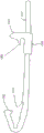
Figure 11 is a side view of a boot system according to another embodiment.
Figure 12 is a side view of a boot system according to another embodiment.
Figure 13 is a bottom view of a toe body according to another embodiment.
Fig. 14 is an exploded bottom view of a fin system according to another embodiment.
Fig. 15 is a partial side view of a fin system according to another embodiment.
Fig. 16 is a top view of a fin apparatus according to another embodiment.
Figure 17 is a bottom view of a boot coupling and a fin according to another embodiment.
Figure 18 is a bottom view of a boot coupling and a fin according to another embodiment.
Figure 19 is a bottom view of a boot coupling and a fin according to another embodiment.
Figure 20 is a bottom view of a boot coupling and a fin according to another embodiment.
Figure 21 is a bottom view of a boot coupling and a fin according to another embodiment.
Figure 22 is a side cross-sectional view of a boot coupling according to another embodiment.
Figure 23 is a side cross-sectional view of the toe body of the boot according to the embodiment of figure 22.
Figure 24 is a partial side cross-sectional view of the boot coupling and boot toe body of figures 22 and 23 with the clasp of the boot coupling in a coupled position.
Figure 25 is a partial side cross-sectional view of the boot coupling and boot toe body of figures 22 and 23 with the clasp of the boot coupling in a decoupled position.
Fig. 26 is a bottom view of a fin device including the boot coupling of fig. 22, with the clasp of the heel coupling in a decoupled position.
Fig. 27 is a side view of the fin system of fig. 1.
Figure 28 is a side view of a clasp according to another embodiment.
Fig. 29 is another exploded top view of the fin system of fig. 1.
Fig. 30 is another exploded top view of the fin system of fig. 1.
Fig. 31 is a top view of the fin device and the toe body of the fin system of fig. 1.
Fig. 32 is a proximal end view of a fin device of the fin system of fig. 1.
Fig. 33 is a distal end view of a fin apparatus of the fin system of fig. 1.
Fig. 34 is a top view of the fin device and the toe body of the fin system of fig. 1.
Figure 35 is a bottom view of a boot coupling and a fin according to another embodiment.
Figure 36 is a bottom view of a boot coupling and a fin according to another embodiment.
Figure 37 is a bottom view of a boot coupling according to another embodiment.
Figure 38 is a bottom view of a boot coupling and a fin according to another embodiment.
Figure 39 is a partial bottom view of a boot coupling according to another embodiment.
Figure 40 is a bottom view of a boot coupling according to another embodiment.
Figure 41 is a bottom view of a portion of a boot, boot coupling, and fin according to another embodiment.
Figure 42 is a bottom view of a boot coupling and a fin according to another embodiment.
Fig. 43 is an exploded bottom view of a fin system according to another embodiment.
Fig. 44 is a side cross-sectional view of the fin frame of the fin system of fig. 43 taken along line 44-44 in fig. 43.
Fig. 45 is an exploded bottom view of the coupling body of the fin system of fig. 43.
Fig. 46 is a side cross-sectional view of a boot coupling including the fin frame and coupling of fig. 43.
Figure 47 is an exploded bottom view of a coupling body according to another embodiment.
Figure 48 is a side cross-sectional view of the coupling body of figure 47 and the boot toe body according to the embodiment of figure 47.
FIG. 49 is a side cross-sectional view of a boot and heel coupling portion of a boot coupling according to another embodiment.
Fig. 50 is a side partial cross-sectional view of a fin system according to another embodiment.
Figure 51 is a side schematic view of a boot coupling according to another embodiment.
Figure 52 is a side schematic view of the boot coupling of figure 51 having a boot toe body coupled to the boot coupling.
Figure 53 is a side schematic view of the boot coupling of figure 51 with the toe body of figure 52 coupled to the boot coupling.
Figure 54 is a side schematic view of the boot toe body of figure 52 ejected from the boot coupling of figure 51.
Figure 55 is a side schematic view of a boot coupling according to another embodiment.
Figure 56 is a side view of a toe body according to another embodiment.
Figure 57 is a side view of a boot shell that can be coupled to figure 56.
Figure 58 is a side view of a boot toe body and boot coupling according to another embodiment.
Figure 59 is a side view of the boot toe body of figure 58 and a boot coupling according to another embodiment.
Figure 60 is a side view of a boot toe body and boot coupling according to another embodiment.
Figure 61 is a side view of a boot toe body, boot coupling, and boot shell according to another embodiment.
Figure 62 is a side view of a boot and toe body according to another embodiment.
FIG. 63 is a side view of a boot shell, liner, and toe body according to another embodiment.
Figure 64 is a side schematic view of a boot coupling according to another embodiment.
FIG. 65 is an exploded top view of a boot and heel coupling portion of a boot coupling according to another embodiment.
FIG. 66 is a side cross-sectional view of the boot and heel coupling portion in an uncoupled state according to the embodiment of FIG. 65.
FIG. 67 is a side cross-sectional view of the boot and heel coupling portion in a coupled condition according to the embodiment of FIG. 65.
Fig. 68 is an exploded bottom view of a fin system according to another embodiment.
Fig. 69 is a side cross-sectional view of the fin system of fig. 68.
Fig. 70 is a top view of the fin system of fig. 68.
FIG. 71 is a side view of a boot coupling and a heel coupling according to another embodiment.
FIG. 72 is an unassembled side view of a boot and heel coupling of a boot coupling according to another embodiment.
FIG. 73 is an assembled side view of the boot and heel coupling according to the alternative embodiment of FIG. 72.
FIG. 74 is a perspective view of a boot coupling and a heel coupling in accordance with another embodiment.
Figure 75 is a perspective view of a boot according to another embodiment.
Fig. 76 is a perspective view of a fin according to another embodiment.
Figure 77 is a side view of a boot and a toe body according to another embodiment.
Fig. 78 is an exploded bottom view of a fin system according to another embodiment.
Fig. 79 is an exploded bottom view of the fin system of fig. 78.
Fig. 80 is an exploded top perspective view of the fin system of fig. 78 showing the shoe coupling of the assembled fin system of fig. 78.
Fig. 81 is a top perspective view of the fin system of fig. 78.
Fig. 82 is a cross-sectional view of the fin system of fig. 78, showing the toe body and showing the shank body of the boot coupling of the fin system of fig. 78 in an open position.
Fig. 83 is a cross-sectional view of the fin system of fig. 78, showing the toe body of fig. 82, and showing the lever body of fig. 82 in a closed position.
Fig. 84 is an exploded top perspective view of the fin system of fig. 78 showing the toe body of fig. 82.
Fig. 85 is a top perspective view of the fin system of fig. 78 showing a toe body according to another embodiment.
Fig. 86 is a bottom perspective view of the fin system of fig. 78 showing the toe body of fig. 85.
Detailed Description
Referring to fig. 1, a fin system according to an embodiment is shown generally at 100 and includes a fin 102, a boot coupler 104, a boot toe 106, and a boot 108.
The fin 102 has a proximal end shown generally at 110 and is configured to couple to the boot coupling 104 and the boot toe 106 as described below. The fin 102 also has a distal end, shown generally at 112, opposite the proximal end 110. The fin 102 has a top side (shown generally at 114) and a bottom side (shown generally at 116).
When a user wearing the fin 102 walks on a surface, the bottom side 116 is generally facing downward and is therefore generally in contact with the surface. Generally, the "bottom" side herein refers to the side that faces downward and generally contacts the surface when the user walks on the surface. However, when using the fin 102 in water, the user may be facing downwards, and the "bottom" side of the fin here refers to the surface that is normally facing upwards when the swimmer is using face down. Further, a "bottom view" herein generally refers to a view of such a "bottom" side, and thus in the case of fins, a "bottom view" herein generally refers to a view from above. Conversely, the "top" side of the fin herein refers to the surface that is normally facing downward when the swimmer is in use, and the "top view" side herein refers generally to such a "top" side, and thus, where the fin is in use, the "top" side herein refers generally to looking from below.
The fin 102 also defines a first through-hole, shown generally at 118, extending between the top and bottom sides 114, 116, and a second through-hole, shown generally at 120, extending between the top and bottom sides 114, 116. The fin 102 includes a retainer 122 positioned in the through hole 118 and extending beyond the bottom side 116. The retainer 122 defines a generally transverse through bore, shown at 124, for receiving a fastener 126, as described below. For example, the retainer 122 may be made of a relatively rigid thermoplastic material and, for example, the fastener 126 may be a metal rivet.
For example, herein, a "relatively rigid thermoplastic material" may refer to a thermoplastic material having a modulus of elasticity of about 100 megapascals (MPa) to about 500 MPa. For example, the components described herein may be made from a variety of materials, including thermoplastic materials, such as thermoplastic polyurethanes, polypropylenes, polyamides, thermoplastic elastomers, styrene-butadiene-styrene, styrene-ethylene-butadiene-styrene, ethylene, polyolefins, acetal resins, polyoxymethylene plastics (e.g., DELRIN @)TMOr DELRIN 107TM) And/or combinations of two or more of the foregoing. These thermoplastic materials may also be fiber filled, and/or composite matrix materials comprising glass and/or carbon fibers, for example.
Referring to figures 1 and 2, the boot coupling 104 is generally semi-circularly curved, with a top portion shown generally at 128, a bottom portion shown generally at 130, and a middle portion shown generally at 132 and extending between the top 128 and bottom 130.
The middle portion 132 defines a socket (shown generally at 134) that is open to the space between the top 128 and bottom 130. As shown in fig. 3 and 4, the socket 134 is sized to receive a portion of the retainer 122. As shown in fig. 5, the distal end of the retainer 122 has two spaced apart lobes, and thus the socket 134 includes two spaced apart grooves for receiving the respective lobes of the retainer 122 (shown in fig. 2). The intermediate portion 132 also defines a generally transverse through-hole, shown generally at 136, and is sized for the fastener 126.
Still referring to fig. 1 and 2, the top portion 128 defines a cage (or retainer) 138 that extends into the space between the top portion 128 and the bottom portion 130, and the bottom portion 130 defines a clasp (or boot) 140 that extends into the space between the top portion 128 and the bottom portion 130. Thus, the boot coupling 104 is a unitary body with a cage 138 and a clasp 140.
Referring to fig. 1-4, the through-hole 118 is sized to receive a portion of the middle portion 132, the top 128 of the portion being located on the top side 114 of the fin 102 and the bottom 130 of the portion being located on the bottom side 116 of the fin 102. As shown in fig. 3 and 4, the boot coupling 104 may be positioned with the intermediate portion 132 in the through-hole 118 such that the through-hole 124 is laterally aligned with the through-hole 136, such that the fastener 126 may be received in the through-hole 124 and the through-hole 136. In position, the retainers 138 extend through the through holes 120 and out the bottom side 116 of the fin 102. The fastener 126 may couple the fin 102 to the boot coupling 104, but in another embodiment, such a fastener may be omitted if the fin and boot coupling may interlock or otherwise couple without such a fastener. Here, as shown in fig. 3 and 4, the "fin device" may refer to an assembly of the fin body 102 and the shoe coupling body 104. In other embodiments, the fin device may include more or fewer portions and may be integrally formed as a single unitary body.
Referring to fig. 1 and 5, the toe body 106 is curved and has a top portion (shown generally at 142), a bottom portion (shown generally at 144), and a middle portion (shown generally at 146) extending between the top portion 142 and the bottom portion 144. The top portion 142 defines a socket (shown generally at 148) that opens to the top side of the toe body 106, and the bottom portion 144 defines a socket (shown generally at 150) that opens to the bottom side of the toe body 106. At the forward end (shown generally at 152), the medial portion 146 defines a groove (shown generally at 154) extending between the top and bottom sides of the toe body 106. The groove 154 defines a front surface 155 that is complementary to the retaining surface 156 on the retainer 122 such that the groove 154 can receive a portion of the retainer 122 when the retaining surface 156 contacts the front surface 155.
Referring to fig. 6, the cage 138 defines a retaining surface 158 that is complementary to a retaining surface 160 in the socket 148. Further, the clasp 140 defines a retention surface 162 that is complementary to a retention surface 164 in the receptacle 150. In the absence of external forces, the intermediate portion 132 is curved such that the curvature of the curved inner surface of the intermediate portion 132 (extending into the space between the top 128 and bottom 130) is greater than the curvature of the complementary outer surface on the toe body 106 front end 152. However, the boot coupling 104 is resiliently deformable, and as described below, coupling the boot toe 106 involves resiliently deforming the boot coupling 104, which reduces the curvature of the curved inner surface of the intermediate portion 132 to a curvature closer to the complementary outer surface on the front end 152 of the boot toe 106, and increases the separation distance between the cage 138 and the clasp 140.
Referring to fig. 7, the forward end 152 of the toe body 106 may be received in the space between the top portion 128 and the sole portion 130 by the cage 138 (which is received in the receptacle 148) such that the retaining surface 158 contacts the retaining surface 160. When the retaining surface 158 contacts the retaining surface 160, the boot toe body 106 may pivot relative to the boot coupling body 104 about a generally transverse axis defined by the contact points of the retaining surface 158 on the retaining surface 160, and the boot coupling body 104 may pivot relative to the boot toe body 106 about a generally transverse axis defined by the contact points of the retaining surface 158 on the retaining surface 160. If the boot toe body 106 rotates about the rotation axis in the direction of arrow 166, or if the boot coupling body 104 rotates about the rotation axis in the direction of arrow 168, or both, the catch 140 and retaining surface 162 approach the socket 150 by moving in the direction of arrow 170.
Fig. 8 shows the clasp 140 closer to the receptacle 150, the clasp moving in the direction of arrow 170 relative to the position shown in fig. 7. The boot coupling 104 is more elastically deformable than the boot toe 106. Thus, as the clasp 140 moves from the position shown in figure 7 to a position closer to the receptacle 150 as shown in figure 8, the boot coupling 104 elastically deforms, which causes the curvature of the curved inner surface of the intermediate portion 132 to decrease closer to the curvature of the complementary outer surface on the front end 152 of the toe body 106 and the separation distance between the cage 138 and clasp 140 to increase.
Since the boot coupling 104 has elastically deformed to increase the separation distance between the cage 138 and the catch 140, the boot coupling 104 elastically urges the catch 140 in a direction generally toward the cage 138. Thus, as shown in fig. 9, as the retaining surface 162 moves in the direction of arrow 170 past the retaining surface 164, the receptacle 150 receives the clasp 140 and the retaining surface 162 of the clasp 140 contacts the retaining surface 164. The retaining surfaces 158, 160, 162 and 164 are positioned to retain the cage 138 and clasp 140 from moving in a direction toward the fin 102, and the clasp 140 is thus connected to the toe body 106 at the socket 150, while the cage 138 is attached to the toe body 106 at the socket 148 with the retaining surface 158 in contact with the retaining surface 160. In various embodiments, a "socket" need not be a recess, but may include other structures that define at least one retention surface to function as a connector.
Thus, the cage 138, the buckle 140, the socket 148, and the socket 150 function as a connector (or boot connector). The cage 138 and the socket 148 are first complementary connectors (or boot connectors) and the buckle 140 and the socket 150 are second complementary connectors (or boot connectors). When the cage 138 is connected to the toe body 106 at the socket 148 and when the clasp 140 is connected to the toe body 106 at the socket 150, the front surface 155 in the groove 154 contacts the retaining face 156 of the retainer 122, the cage 138 and clasp 140 being positioned such that the front surface 155 abuts the retaining face 156. Although the boot coupler 104 is elastically deformed by the boot toe body 106, the retainer 122 is more rigid and does not significantly elastically deform by the boot toe body 106, so the boot toe body 106 can be securely held against the retainer 122. Thus, the cage 138, the catch 140, and the retainer 122 cooperate to retain the toe body 106 from moving relative to the boot coupling 104 to couple the toe body 106 to the boot coupling 104. Further, since the front surface 155 is complementary to the retaining surface 156, the retainer cooperates with the front end 152 of the boot toe body 106 to align the boot toe body 106 with the boot coupling 104 and inhibit lateral and rotational movement of the boot toe body 106 relative to the boot coupling 104. In sum, the boot coupler 104 and the boot toe body 106 may cooperate to automatically align the boot toe body 106 with the boot coupler 104, which facilitates coupling of the boot toe body 106 to the boot coupler 104.
The embodiments shown in fig. 1-9 may facilitate a simple and intuitive method of coupling and decoupling a fin device to a boot, as a user may couple the fin device to the boot by "inserting" a boot coupling body to the fin device with one hand or without the hand at all.
As shown in fig. 9, in some embodiments, the boot coupling may be permanently coupled to the toe body. However, in other embodiments, the boot coupling may be decoupled from the boot toe body.
Referring to fig. 10, a fin system according to another embodiment is shown generally at 172 and includes a fin 174, a boot coupler 176, a boot toe 106, and a boot 178. The fin 174 is substantially identical to the fin 102 and the toe body 178 is substantially identical to the toe body 106. The boot coupling 176 is substantially identical to boot coupling 104 and also includes a clasp (or boot clasp) 180 that is substantially identical to clasp 140, but boot coupling 176 includes a rigid rod 182 that is coupled to clasp 180 and extends behind clasp 180. Moving rod 182 away from boot toe body 178 in direction 184 causes a force to be transferred from rod 182 to clasp 180 to release or decouple boot coupling 176 (and thus fin 174 coupled to boot coupling 176) from boot toe body 178 because the portion of boot coupling 176 forward of clasp 180 is sufficiently flexible to allow clasp 180 to withdraw from the socket or connector of boot toe body 178 in response to a force from rod 182 exiting boot toe body 178. The lever 182 may include a safety lock (not shown) to prevent accidental release. For example, fig. 41 shows a rigid rod 292 including a safety lock 294. Further, fig. 42 illustrates a rigid rod 296 in accordance with another embodiment, wherein the rod 296 includes a heel coupling body as described below.
As shown in fig. 5, the boot toe body 106 may be coupled to the boot 108. For example, the toe body 106 may be formed by injection molding, and the boot 108 may be made of neoprene or the like material and sewn, glued, or otherwise secured to the toe body 106. Alternatively, for example, the boot toe body 106 and the boot 108 may be integrally formed by multi-stage injection molding. In some embodiments, the toe body of the boot may extend far beyond the toe region (e.g., as shown in fig. 13), and may comprise, for example, part or all of the entire boot.
Generally, the boot toe bodies described herein may be molded (or otherwise formed) into one or a few sizes and then coupled to boots of different sizes and materials. Accordingly, one or a small number of sizes of boot toe bodies may be fabricated to facilitate coupling to a fin device (such as the fin devices described herein). Manufacturing one or a small number of sizes of toe bodies may reduce manufacturing costs compared to other boot binding systems, as one or a small number of sizes of toe bodies may be coupled to a variety of different boots. For example, boots may be manufactured by many manufacturers in a wide variety of varieties that may vary depending on the size and shape of the foot, materials, ankle support, and many other aspects, without the need for separate tools or injection molds to manufacture different toe bodies for each type of boot. For example, the toe body 106 may be coupled to a low ankle boot 188 as shown in FIG. 11 or a high ankle boot 190 as shown in FIG. 12. Further, referring to fig. 14, the boot toe body 106 may be coupled to a boot shell 192, and the boot shell 192 may be configured to receive a boot and be coupled to a boot 194.
Further, for example, the boots described herein may be similar to the boots described and illustrated in U.S. provisional patent application 61/322,104 filed 4/8/2010, or similar to the boots described and illustrated in U.S. patent application 13/639,446.
Referring to fig. 15, another embodiment includes a toe body 196 similar to the toe body 106, except that the toe body 196 is configured to be attachably and detachably coupled to the boot 198. For example, the toe body 196 may include a height adjustment mechanism 200 for adjusting the height of the socket of the toe body 196 to suit a particular boot 198. The toe body 196 may also include a heel coupling 202 having a third connector (or third boot connector) configured to couple to a heel region (shown generally at 204) of the boot 198. The length of heel coupling body 202 may be adjusted to accommodate different lengths and sizes of boot 198, and thus the separation distance between the first and second connectors and the third connector. For example, the boot toe 196 may couple the fin apparatus to a dry-suit or a user's preferred boot.
Further, the boots and toe bodies described herein may include a sole body such as the sole body described and illustrated in PCT international application PCT/CA 2012/000946. Further, the "boot" herein is not limited to any particular footwear, and may include shoes and other footwear, as well as, for example, prosthetics. Figure 40 shows a toe body according to another embodiment wherein the hinge 290 allows for greater flexibility between the toe and heel portions of the toe body.
Furthermore, fin devices may vary in many ways (e.g., in length, width, shape, material, and flexibility). For example, the fin device described herein may be similar to the fin device (or "flipper") described and illustrated in U.S. provisional patent application 61/322,104, or similar to the fin device (or "flipper") described and illustrated in U.S. patent application 13/639,446. Fig. 16 shows fin devices 206, 208, 210, 212, and 214 according to other embodiments.
Referring to FIG. 17, another embodiment includes a boot coupling 216 similar to those described herein, but the boot coupling 216 includes a heel coupling 218. The heel coupling body 218 includes side posts 220 and 222, the side posts 220 and 222 configured to attach to a coil spring band (not shown) to extend between the side posts 220 and 222 and behind a heel region of the boot (e.g., the heel region 204 of the boot 198 or the heel region of the boot 108 (shown generally at 224)).
Referring to FIG. 18, another embodiment includes a boot coupling 226 similar to those described herein, but the boot coupling 216 includes a heel coupling 228. The heel coupling body 228 has a ring shape with a rear portion, generally shown as 230. At rear portion 230, heel coupling 228 includes a connector (or boot connector) 232, and connector (or boot connector) 232 is receivable in a socket at the heel end of the boot (e.g., socket 1050 shown in fig. 37 of PCT international application No. PCT/CA 2011/000395). The loop of the heel coupling body 228 is elastically deformable to stretch around the rear portion 230 of the heel of the boot, and the length of the loop portion of the heel coupling body 228 is adjustable.
Fig. 19 to 21 and fig. 35 to 39 show length adjustment in other embodiments. Figure 19 shows a boot coupling having a resiliently extendable heel coupling 236. Figures 35-39 also illustrate a boot coupling having a resiliently extendable heel coupling. Fig. 20 shows a boot coupling 238 having a heel coupling 240 that is adjustable in length by positioning a connector 242 in different apertures 244, 246 and 248 of the boot coupling 238. Figures 35, 36, 37 and 39 also illustrate a boot coupling having a heel coupling that is adjustable in length. Fig. 21 illustrates a replaceable semi-rigid heel coupling body 250.
Referring to FIG. 22, a boot coupling according to another embodiment is shown generally at 252 and is similar to the boot coupling described above. The boot coupling 252 has a top side (shown generally at 254) and a bottom side (shown generally at 256). The boot coupler 252 also has a clasp (or boot clasp) 258 coupled to the boot coupler 252 by a generally cylindrical fastener 260 coupled to the boot coupler 252 for rotation about an axis of rotation 262 extending between the top side 254 and the bottom side 256 of the boot coupler 252. Thus, the clasp 258 is coupled to the boot coupling body 252 for rotation about an axis of rotation 262. The boot coupling 252 also includes a heel coupling 264 that is connectable to a connector (or boot connector) 266 at the heel end of the boot. Heel coupling body 264 is also coupled to fastener 260 for rotation about rotational axis 262. Thus, rotation of heel coupling body 264 about rotational axis 262 transfers torque to fastener 260 and clasp 258, thereby rotating clasp 258 about rotational axis 262 in response to rotation of heel coupling body 264 about rotational axis 262. The catch 258 defines a retainer 268 having a retaining surface 270 facing the bottom side 256 of the boot coupling body 252.
Referring to fig. 23, the toe body 272 according to the embodiment of fig. 22 is similar to the toe bodies described above, and the toe body 272 has a top side (shown generally at 274) and a bottom side (shown generally at 276). On the bottom side 276, the toe body 272 defines a socket 278, the socket 278 defining a retaining surface 280 facing the top side 274 of the toe body 272.
Referring to fig. 24 and 25, when the catch 258 is rotated about the axis of rotation 262 such that the retainer 268 is positioned above the retaining surface 280, the retaining surface 270 contacts the retaining surface 280 to retain the catch 258 in the receptacle 278, and the catch 258 thus acts as a connector (or as a boot connector) to connect the boot coupling 252 to the boot toe 272, the catch 258, and thus the receptacle 278 is a complementary connector (or boot connector). However, when clasp 258 is rotated about axis of rotation 262 such that retainer 268 is no longer above retaining surface 280, then clasp 258 no longer connects boot coupling 252 to boot toe 272 at socket 278 and boot coupling 252 is thus decoupled from boot toe 272.
In some embodiments, the clasp 258 may be made of a material such as polytetrafluoroethylene (or polytetrafluoroethylene (TM)) or may include an insert of a material to reduce friction and facilitate sliding on the retaining surface 280. Figure 28 shows a clasp (or boot clasp), shown generally at 286, according to another embodiment. The clasp 286 includes a roller 288 to facilitate snapping onto the retention surface 280. The rollers 288 may also be made of or may include inserts of a material such as polytetrafluoroethylene (or teflon) to reduce friction and facilitate sliding on the retaining surface 280. The roller 288 may also have an elliptical cross-sectional shape to facilitate snapping onto the retaining surface 280, for example, to snap the fin arrangement into the toe box when the clasp 286 is in a coupled position (similar to the position shown in fig. 24) or a partially coupled position (similar to between the positions shown in fig. 24 and 25), for example, for use in water. Referring to fig. 26, the heel coupling body 264 may be rotated to a stowed position toward the distal end of the fin to enable storage or transfer of the fin apparatus. Fig. 35-39 illustrate other embodiments including a rotatable clasp coupled to a heel coupling body.
The embodiment of fig. 22-26 enables a simple and intuitive method of coupling and decoupling the fin apparatus to the boot, as the user can couple the fin apparatus to the boot in a single action with only one hand by rotating the heel coupling body 264 into a position in which the heel coupling body 264 is connected with the heel of the boot, and the user can decouple the fin apparatus from the boot in a single action again with only one hand by rotating the heel coupling body 264 into a position in which the heel coupling body 264 is disconnected from the heel of the boot. The heel coupling body 264 may include a safety lock (not shown) to prevent accidental release.
Referring to fig. 27, the fin system of fig. 1 is shown assembled with the top surface 282 of the fin body 102 generally coplanar with the top surface 284 of the toe body 106. As mentioned above, swimmers who use fin systems (such as those described above) will typically face downward when swimming, and thus top surface 282 and top surface 284 face generally downward when in use. Furthermore, the swimmer's most powerful kicks are usually downward kicks, so the swimmer's propulsion is usually strongly dependent on the powerful downward kicks. During downward kicking, water flows over the top surface 284 and the top surface 282, and in some embodiments, positioning the top surface 282 generally coplanar with the top surface 284 can cause the water to more fluidize and efficiently flow from the top surface 284 to the top surface 282 during downward kicking. Thus, as shown in the embodiments described above, having the fin body 102 with the top surface 282 positioned generally coplanar with the top surface 284 may allow for more efficient flow of liquid than other fin systems.
Referring to fig. 43, a fin system according to another embodiment is shown generally at 300 and includes a shoe coupling (shown generally at 302). The boot coupling 302 includes a coupling 304 and a fin frame 306. The fin system 300 also includes a boot toe body 308 (not shown) that is attachable to the boot. The fin frame 306 may be integrally, permanently, removably or non-removably coupled to the fin body 307, and when the fin frame 306 is coupled to the fin body 307, the fin frame 306 and the fin body 307 may work together, essentially the same function as the other fin bodies described above (e.g., fin body 102 or the fin bodies shown in fig. 16, 21, 26, 35, 36 and 42). Further, the other fins described above (e.g., fin 102 or the fins shown in fig. 16, 21, 26, 35, 36, and 42) may be understood to include a fin frame (e.g., similar to fin frame 306) that may or may not be removably coupled to a fin (e.g., similar to fin 307) and a boot coupling that may be removably coupled to the fin frame as described herein.
The fin frame 306 has a top side (shown generally at 312), a bottom side (shown generally at 314), a proximal end (shown generally at 316), a distal end (shown generally at 318 and 320), and a retaining member (or fin retaining member) 322 extending longitudinally from the proximal end 316 and laterally centered between the two distal ends 318 and 320. The retaining member 322 also protrudes from the top 312 of the fin frame and then curves into a generally semi-circular shape toward the proximal end 316. The retaining member 322 includes a top portion 324 and an intermediate portion 326. The top 324 of the retaining member 322 defines a retaining surface (or fin retaining surface) 328. The retaining member 322 is resiliently deformable such that applying a downward force on the top 324 will reduce the space between the top 324 and the top side 312 of the fin frame 306.
Referring to fig. 43 and 44, the fin frame 306 further includes a holder (or retainer) 330 extending downwardly into the space from a bottom side 314 of a proximal end 316 of the fin frame 306. The cage 330 defines a complementary retaining surface 332 to a retaining surface 334 defined on the toe body 308. The fin frame 306 also defines an adjustable retaining surface 336 sized to be received in a corresponding groove 337 on the toe body 308. The position of the adjustable retaining surface 336 may be adjusted to adjust the amount that the adjustable retaining surface 336 extends from the remainder of the fin frame 306. In the illustrated embodiment, the position of the adjustable retaining surface 336 is adjusted using an adjustment tool that includes a threaded member 338 that passes through the center of the skeg frame 306. Around the adjustable retaining surface 336 and below the cage 330, the fin frame 306 defines a tapered surface such that when the toe body 308 approaches the fin frame 306, the fin frame 306 may automatically center or align relative to the toe body 308, which facilitates coupling the toe body 308 to the boot coupling 302 with hands-free motion by "insertion" (described below).
The coupling body 304 is similar to the boot coupling body 252 shown in figure 22 and is curved in a generally semi-circular shape having a top 340, a bottom 342, a middle portion 344 extending between the bottom 342 of the top 340, and a catch (or boot catch) 346 on the bottom. The middle portion 344 defines a through-hole 348, the through-hole 348 being sized to receive the retaining member 322 of the skeg frame 306. Through-hole 348 defines a retaining surface (or fin retaining surface) 350 that is complementary to retaining surface 328 of retaining member 322 such that when retaining member 322 is received in through-hole 348 of coupling body 304, retaining surfaces 350 and 328 act as a connector (or boot connector) to couple fin frame 306 to coupling body 304. Additionally, retaining surfaces 350 and 328 may be disengaged from one another to allow removal of retaining member 322 from through-hole 348 to detach fin frame 306 from coupling body 304. Thus, the boot coupling 302 of the illustrated embodiment may include a fin frame 306 coupled (or detachably coupled) to the coupling 304.
Referring to fig. 45, the clasp 346 of the coupling body 304 is coupled to the support body 354 by a cylindrical fastener 353 to allow the clasp 346 to rotate relative to the support body 354. The support 354 is coupled to the base 342 and the coupling body 304 by a fastener 352 such that the base 342, and the support 354 and clasp 346, are rotatable about an axis of rotation 355 defined by the fastener 352. The support 354 is resiliently deformable to allow the clasp 346 to resiliently move away in a downward direction from the rest position. Thus, the boot coupling 302 can be elastically deformed (at least by the elastic deformation of the support 354, the support 354 also acts as a spring) to change the separation distance between the cage 330 and the clasp 346. The catch 346 is sized to be received by the retaining surface 356 of the toe body 308.
The coupling body 304 also has an alignment member (shown generally at 358) that is rotationally coupled to the support body 354 such that rotation of the alignment member 358 about the axis of rotation 355 causes similar rotation of the support body 354 about the axis of rotation 355. Thus, alignment member 358 helps rotate clasp 346 about axis of rotation 355. The alignment member 358 also defines a curved retaining surface 360 that extends longitudinally beyond the catch 346 and is sized to be received by a longitudinal groove (shown, for example, in fig. 13) of the sole of a boot or toe body (e.g., toe body 308). In some embodiments, alignment member 358 may be replaced with rigid rod 182 in fig. 10 or a heel coupling (e.g., heel coupling 202 in fig. 15 or any of the heel couplings shown in fig. 17-22). In embodiments including a heel coupling, the heel coupling may also be rotatably coupled to the catch 346 to rotate about an axis of rotation 355, so when the heel coupling is coupled to a connector on the heel of a boot (or boot connector), the heel coupling may prevent movement of the catch 346, which may prevent release of the catch 346 from the retaining surface 356, thereby preventing release of the boot coupling 302 from the toe body 308.
When the boot coupling body 302 is fitted with the fin frame 306 coupled with the coupling body 304 and the retaining member 322 is received in the through hole 348 as shown in fig. 46, a user wearing a boot including or coupled to the toe body 308 may connect a connector or boot connector (retaining surface 332) to a complementary connector or complementary boot connector (retaining surface 334 as shown in fig. 43) and apply a downward force to the clasp 346, causing elastic deformation of the support body 354 when the clasp 346 is resiliently moved downward until the clasp 346 rolls over the edge of the retaining surface 356, and when the support body 354 resiliently pushes the clasp 346 upward again, the connector "snaps" into the clasp 346, thereby connecting the clasp 346 to the retaining surface 356. Thus, the clasp 346 is a roller and the boot toe body 308 may be coupled to the boot coupling 302 by "plugging" into the boot coupling 302 in hands-free motion.
Alternatively, when the clasp 346 rotates about the axis of rotation 355 to a position where the retaining surface 356 may be accessed without contacting the retaining surface 356, a user wearing a boot including or coupled to the boot toe body 308 may connect a connector or boot connector (retaining surface 332) to a complementary connector or complementary boot connector (retaining surface 334 shown in FIG. 43) so that the clasp 346 may rotate about the axis of rotation 355 to a position where the clasp 346 is connected to the retaining surface 356. As shown in fig. 46, the rotation shaft 355 has an angle at which the top side is inclined away from the skeg frame 306 and the bottom side is inclined toward the skeg frame 306, such an angle causing the clasp 346 to move downward (so as to be in a direction away from the top side and in contact with the holding surface 356) when the clasp 346 is rotated about the rotation shaft 355 in a direction connecting the clasp 346 with the holding surface 356.
Either way, once the catch 346 is connected to the retaining surface 356, connecting the toe body 308 to the boot coupling 302, the adjustable retaining surface 336 will be received against the retaining surface in the groove 337, the retaining surface 332 of the cage 330 will be received against the retaining surface 334, and the catch 346 will be received against the retaining surface 356, effectively locking the toe body 308 to the boot coupling 302. In addition, the curved retaining surface 360 may be received by a longitudinal groove in the sole of a boot or toe body (e.g., toe body 308) (as shown in fig. 13) when the clasp 346 has "snapped" into place against the retaining surface 356.
The embodiment of fig. 43-46 may enable a simple and intuitive method of coupling and decoupling the fin device to the boot, as the user may couple the fin device to the boot including or coupled to the boot-toe body by engaging the cage against the retaining surface of the boot-toe body, align the boot-and-boot-coupler by rotating the alignment member so that the boot-coupler is centrally aligned with the boot-toe body, then rotate the boot-toe body relative to the boot-coupler about a generally lateral axis of rotation, elastically deform the clasp and coupler in a downward direction so that it approaches the corresponding retaining surface of the boot-toe body until it "snaps" into place against the corresponding retaining surface of the boot-toe body. Alternatively, when the clasp is rotated to a position where the clasp can access the retaining face 356 without contacting the retaining face 356, the user can engage the cage against the toe body's retaining member 322 and then can rotate the clasp to a position connecting the clasp to the retaining face 356. Either way, the fin device may be coupled to the boot until the clasp is rotated to a position that may disengage the clasp from the retaining surface 356 to disengage the toe body 308 from the boot coupling body 302. As shown in fig. 46, the rotation shaft 355 has an angle at which the top side is inclined away from the skeg frame 306 and the bottom side is inclined toward the skeg frame 306, such an angle causing the catch 346 to move upward (so as to be in a direction toward the top side and out of contact with the holding surface 356) when the catch 346 is rotated about the rotation shaft 355 in a direction to separate the catch 346 from the holding surface 356.
Referring to fig. 47 and 48, a fin apparatus 400 according to another embodiment includes a shoe coupling (shown generally at 402). The fin device 400 also includes a boot toe body 404 integrated or permanently coupled to a boot 406. In an alternative embodiment, the boot toe body 404 may be removably coupled to the boot 406. The boot coupling 402 includes a coupling 408 and a fin frame 410. In some embodiments, a fin (not shown) may be integrally or permanently coupled to the fin frame 410. In other embodiments, the fin may be removably coupled to the fin frame 410.
In the illustrated embodiment, the fin frame 410 may be removably coupled to the coupler 408 to form the boot coupler 402. In some embodiments, the fin frame 410 may be removably coupled to the coupling body 408 using two respective retaining curved surfaces on each of the fin frame 410 and the coupling body 408 (e.g., with reference to the methods described in fig. 43-46).
The fin frame 410 defines a cage (or retention body) 430 defining a retention surface 431, the retention surface 431 sized to be received against a retention surface 432 when the shoe coupling 402 is coupled to the toe body 404.
The coupling body 408 is similar to the boot coupling body 252 depicted in FIG. 22, and is curved in a generally semi-circular shape having a top portion (shown generally at 412), a bottom portion 414, and an intermediate portion 416 extending between the top portion 412 and the bottom portion 414, and a clasp (or boot clasp) 418 secured to the bottom portion 414 with a fastener 420. The fastener 420 secures the catch 418 by extending laterally through the slot 436 and allows the catch 418 to rotate relative to the base 414, so the catch 418 is also a roller. The slot 436 is elongated in a generally vertical direction to allow the fastener 420 (and thus the clasp 418) to move vertically up and down within the slot 436. The clasp 418 may be similar to the clasp 286 shown in fig. 28.
The bottom portion 414 of the coupling body 408 may extend longitudinally away from the front of the boot 406 and may include a rigid rod (e.g., rigid rod 182 in fig. 10) or a heel coupling body (e.g., heel coupling body 202 in fig. 15 or any of the heel coupling bodies described in fig. 17-22). The sole 414 of the boot coupler 408 may be sized to be received in a longitudinal groove, which may be located at the sole of the boot 406 or at the sole of the toe body 404 (not shown).
The middle portion 416 of the coupling body 408 defines a rotational interface 424, and either the top portion 412 or the bottom portion 414 of the coupling body 408 is rotatable about the rotational interface 424. Fastener 426 acts as a pivot for rotation as this rotation occurs and also couples top portion 412 and bottom portion 414 of coupling body 408 together. When coupled to the fin frame 410, rotation of the coupling body 408 may provide an advantage in storage and protection of the fin device 400 when it is transported or not in use, as the bottom portion 414 of the coupling body 408 may rotate to be parallel to the fin frame 410, thereby reducing the size of the overall device and protecting the bottom portion 414 (which may include a long longitudinal extension, such as a heel coupling body or rigid rod).
In the embodiment shown, the clasp 418 is located above the spring 422, but is not attached to the spring 422, the spring 422 being made of an elastically deformable material. The spring 422 is secured within the base 414 of the coupling body 408 using fasteners 426 and 428. When a downward force is applied to the catch 418, the catch 418 will move downward against the spring 422. Because the spring 422 is elastically deformed, the catch 418 will return to its original position upon removal of any downward force on the catch 418. Thus, the boot coupling 402 may be elastically deformed (at least by the elastic deformation of the spring 422) to change the separation distance between the cage 430 and the catch 418.
The toe body 404 defines a retaining surface 432 sized to receive the cage 430. The toe body 404 also defines a retaining surface 434 on the underside of the toe body. The retaining surface 434 is sized to receive the catch 418 of the coupling body 408 when coupling the boot coupling body 402 to the toe body 404.
The illustrated embodiment facilitates a simple and intuitive method of coupling and decoupling a fin device including at least a boot coupler 402 and a boot toe 404. The user may couple the boot coupling 402 to a boot including the boot toe 404 by engaging the cage 430 against the retaining surface 432 of the boot toe 404, aligning the boot toe 404 with the boot coupling 402 by rotating the sole portion 414 about the axis of rotation defined by the fastener 426, thereby aligning the clasp 418 with the retaining surface 434 of the boot toe 404, and then rotating the boot toe 404 about a generally transverse axis of rotation formed between the top portion 412 and the sole portion 414 of the coupling 408 relative to the boot coupling 402, thereby causing the boot toe 404 to exert a downward force on the clasp. The downward force on the catch 418 causes it to move downward due to the corresponding elastic deformation of the spring 422. As the toe body 404 further deforms the spring 422, the clasps 418 approach the corresponding retaining surfaces 434 of the toe body 404 until the clasps "snap" into place against the corresponding retaining surfaces 434. Alternatively, when the clasp is rotated to a position where the clasp can access the retaining face 434 without contacting the retaining face 434, the user can engage the cage against the retaining face 432 of the toe body and then can rotate the clasp to a position connecting the clasp to the retaining face 434. Either way, the fin device may be coupled to the boot until the clasp is rotated to a position that may separate the clasp from the retaining surface.
Figure 64 shows a boot coupling according to another embodiment. The boot coupling of fig. 64 is similar to the boot coupling 402 shown in fig. 47 and 48 and includes a clasp, boot clasp, or roller 722 that is separate from the spring 724 and is movable relative to the spring 724 in the area of the recess defined by the spring 724. The spring (e.g., spring 724) may be a thermoplastic leaf spring or other type of spring (which may be made of other materials).
Referring to figure 49, another embodiment of a boot coupling 600 is similar to the boot coupling 402 shown in figures 47 and 48. The boot coupling 600 includes a coupling body 602 (shown generally at 602) and a fin frame 604. In some embodiments, a fin (not shown) may be integrally or permanently coupled to the fin frame 604. In other embodiments, the fin may be removably coupled to the fin frame 604.
In the illustrated embodiment, the fin frame 604 may be removably coupled to the coupling body 602 to form the boot coupling body 600. In some embodiments, fin frame 604 may be removably coupled to coupling body 602 using two respective retaining curved surfaces on each of fin frame 604 and coupling body 602 (e.g., with reference to the methods described in fig. 43-46).
The fin frame 604 defines a cage (or retention body) 606 that includes a retention surface 608, and the retention surface 431 may be sized to be received against a corresponding retention surface 432 on the toe body in a manner similar to that described with reference to fig. 47 and 48.
The coupling body 602 is similar to the coupling body 408 described in fig. 47 and 48 in that the coupling body 602 is curved in a generally semi-circular shape having a top portion (shown generally at 610), a bottom portion (shown generally at 612), and an intermediate portion (shown generally at 614) extending between the top portion 610 and the bottom portion 612.
The bottom portion 612 of the coupling body 602 may extend longitudinally away from the front of the fin frame 604 and may include a rigid rod (e.g., rigid rod 182 in fig. 10) or a heel coupling body (e.g., heel coupling body 202 in fig. 15 or any of the heel coupling bodies described in fig. 17-22).
The middle portion 614 of the coupling body 602 defines a rotational interface 616, and either the top portion 610 or the bottom portion 612 of the coupling body 602 is rotatable about the rotational interface 424. Fastener 618 acts as a pivot for rotation as the rotation occurs and also couples top portion 610 and bottom portion 612 together. When coupled to fin frame 604, rotation of coupling body 602 may provide the same advantages to a fin device including the present embodiment as described with reference to fig. 47 and 48.
In the illustrated embodiment, spring 620 is secured within bottom portion 612 of coupling body 602 with fasteners 618 and 622. The spring 620 is made of an elastically deformable material, similar to the spring 422 shown in fig. 47 and 48. However, in the illustrated embodiment, spring 620 defines an integral hook (or clasp or boot) 624 composed of or comprising the same elastically deformable material as spring 620. In the illustrated embodiment, the hook 624 and the spring 620 are part of a single body, which may be produced as a single piece using injection molding techniques, for example. The hook 624 functions in substantially the same manner as the hook 418 shown in fig. 47 and 48, and when a downward force is applied to the top of the hook 624, the hook 624 can be elastically deformed in a downward direction along the spring 620. Because the spring 620 and the hook 624 are elastically deformed, the hook 418 will return to its original position upon removal of any downward force on the hook 624.
The illustrated embodiment facilitates the same simple and intuitive method of coupling and decoupling a fin device including at least the boot coupling body 600 to a boot toe body (not shown) similar to that described with reference to fig. 47 and 48. Replacing the catch 418 with an integral hook 624 may provide durability and longevity advantages of the coupling body 600. The illustrated embodiment may also provide advantages during production and manufacture of the coupling body 602.
Referring to FIG. 50, an embodiment of a heel coupling body 502 is shown. The heel coupling 502 may be an extension of the sole portion 504 of the boot coupling described in previous embodiments (not shown) and is designed to be removably coupled to the heel 506 of a boot 508. The boot 508 need not be a complete boot, but may be an open heel body for receiving a boot or for receiving a foot or prosthesis, for example, in various embodiments. The heel coupling body 502 includes a retaining surface 509, the retaining surface 509 sized to be received against a corresponding retaining surface 510.
The heel coupling body 502 also defines a rod mechanism, shown generally at 512, and includes a rod 514, a wedge 516, and an actuator 518. When the retaining surfaces 509 are received against the respective retaining surfaces 510, the actuator 518 contacts the surface 524 of the shoe 508, which causes the lever mechanism 512 to rotate about the fastener 522 in a direction that causes the wedge 516 to abut the lock 520, which causes the retaining surface 509 to abut the retaining surface 510, such that the heel coupling 502 is substantially "locked" in position against the heel 506 of the shoe 508. A user operating the illustrated embodiment may "unlock" the heel coupling 502 from the boot 508 by rotating the stem 514 in a generally rearward direction about the fastener 522. Thus, removal of the wedge 516 from contact with the lock 520 stops the retaining surface 509 from abutting the retaining surface 510, and the actuator 518 then applies a force against the surface 524, urging the retaining surface 509 rearwardly away from the retaining surface 510 to move the heel coupling body 502 rearwardly and away from the "locked" position against the heel 506 of the boot 508.
Referring to fig. 51, a boot coupling according to another embodiment is shown generally at 628 and includes a toe coupling region (shown generally at 630) and is substantially identical to the coupling 408 and the fin frame 410 shown in fig. 47 and 48. The boot coupling body 628 also includes a heel coupling body, shown generally at 632, that is similar to the heel coupling body 502 shown in fig. 50, except that the heel coupling body 632 defines recesses, shown generally at 634, 636 and 638, to receive the wedge 640 at three locations defined by each recess 634, 636 and 638. Rod 642 and actuator 644 may move wedge 640 in substantially the same manner as rod 514 and actuator 518, respectively, described above with reference to fig. 50, but resiliently urge wedge 640 into recesses 634, 636, and 638 such that the wedge is more naturally located in one of the three positions defined by recesses 634, 636, and 638.
As shown in fig. 52, the rod 642 may be moved to position the wedge 640 in the recess 634, thereby moving the wedge 640 into a position coupled to the heel region of the toe body 646. Then, as shown in fig. 53, the user may straddle the boot coupling 628 and, in doing so, transfer force from the underside of the toe body 646 to the actuator 644, which (as described above with reference to fig. 50) may urge the wedge into the position defined by the recess 638 and lock the heel coupling 632 to the heel region of the toe body 646. Thus, in various embodiments such as those described herein, the connection to the heel region need not be on the boot itself, but may be on the toe body 646, or on any other body coupled to or possibly coupled to the bootie. As shown in fig. 54, the rod 642 may be pulled out of the heel region of the toe 646 to eject the toe 646 from the boot coupling 628.
Referring to fig. 55, a boot coupling according to another embodiment is shown generally at 648 and includes a toe coupling region (shown generally at 650), and is similar to the coupling 408 and the fin frame 410 shown in fig. 47 and 48. The boot coupling 648 further includes a heel coupling, shown generally at 652, that is substantially identical to the heel coupling 632 shown in fig. 51-54. Toe coupling region 650 includes a clasp (or boot clasp) 654 substantially identical to clasp 418 shown in fig. 47 and 48, but clasp 654 is coupled to or integral with a spring 656 secured by fasteners 658 and 660. As shown in fig. 55, spring 656 is elastically deformable to allow elastic movement of clasp 654 as shown in fig. 55 and generally described above.
Referring to fig. 56 and 57, a boot toe body according to another embodiment is shown generally at 662 and is configured to be removably coupled to a toe coupling region (shown generally at 664) of a boot coupling at a coupling region of the boot toe body 662 and is substantially identical to the coupling 408 and fin frame 410 shown in fig. 47 and 48. For example, the toe 662 is also configured to be removably coupled to a boot shell 666, which boot shell 666 may be temporarily, removably, non-removably, permanently, or integrally coupled to a dry-suit, a user-preferred boot, a pad, or a bootie. Referring to fig. 8, the toe body 662 may be configured to removably couple to a boot coupling 668, the boot coupling also having a heel coupling (shown generally at 670) that is substantially the same as the heel coupling 502 shown in fig. 50. Fig. 61 shows an embodiment that includes a boot toe body, shown generally at 682 (which is similar to boot toe body 662), which is removably coupled to the toe coupling region of the boot toe coupling, shown generally at 684 (which is also similar to coupling 408 and fin frame 410 shown in fig. 47 and 48), and which is removably coupled to the boot shell of the boot, shown generally at 686 (which is similar to boot shell 666).
Referring to fig. 59, a toe body according to another embodiment is shown generally at 672 and is configured to detachably couple at a toe region of the toe body 672 to a toe coupling region of a toe coupling shown generally at 674 (which is substantially identical to the coupling 408 and the fin frame 410 shown in fig. 47 and 48) and is also configured to detachably couple at a heel region of the toe body 672 to a heel coupling shown generally at 676 of the toe body 674 (which is substantially identical to the heel coupling 502 shown in fig. 50). The toe body 662 is also configured to be removably coupled to a dry-suit or user-preferred boot, for example, which may be received in a sandal-like structure of either toe body 674. Fig. 60 shows an embodiment including a boot (shown generally at 678) that may be removably coupled to a sandal-like boot toe body (shown generally at 680).
Referring to fig. 62, a boot assembly according to another embodiment is shown generally at 688 and includes a boot 690, which may be, for example, a one-piece boot or may be a boot liner or bootie combined with a boot shell. The boot assembly 688 further includes a boot toe body 692, the boot toe body 692 being connectable to the boot coupling body in the toe region as described herein or also in the heel region. The boot 690 includes a connector (shown generally at 694) on the upper side of the toe region of the boot 690, and the connecting surface of the connector 694 is complementary to the connecting surface of the connector (shown generally at 696) on the upper side of the toe region of the boot toe body 692. The boot 690 also includes a connector (shown generally at 698) on the heel region of the boot 690, and the connecting surface of the connector 698 is complementary to the connecting surface of a connector (shown generally at 700) on the heel region of the toe body 692. Thus, the connectors 694, 696, 698 and 700 may help to removably attach the boot 690 to the boot toe body 692.
Referring to fig. 63, a boot assembly in accordance with another embodiment is shown generally at 702 and includes a boot shell 704, which boot shell 704 may be temporarily, removably, non-removably, permanently or integrally coupled (e.g., by snapping, gluing, stitching or other shoe manufacturing techniques) to a neoprene sock or bootie 706. The combination of the boot shell 704 and the bootie pad 706 may form a relatively very light boot that may be desirable for some embodiments. The boot assembly 702 also includes a boot toe body 708, the boot toe body 692 being connectable to the boot coupling at the toe region as described herein or also at the heel region. The pad 706 includes connectors shown generally at 710 and 712 (in the illustrated embodiment, these connectors are sewn into a flexible hook or other pad element) located on the upper side of the toe region of the pad 706, with the connecting surfaces of the connectors 710 and 712 being complementary to the connecting surfaces of the connectors (shown generally at 714 and 716) located on the upper side of the toe region of the boot toe body 708, respectively. The pad 706 also includes a connector (shown generally at 718) on the heel region of the pad 706, and a connecting surface of the connector 718 is complementary to a connecting surface of a connector (shown generally at 720) on the heel region of the toe body 708. Thus, the connectors 710, 712, 714, 716, 718, and 720 may facilitate removably attaching the pad 706 to the boot toe body 708. More generally, in some embodiments, a "boot" herein may include a combination of a shell and a permanently coupled or replaceable liner. Further, the shell 704 may transfer forces from fins (not shown) coupled to the toe region of the shell 704 to other regions of the user's foot in the pad 706, and in various other embodiments, such a shell or other similar structure may transfer forces from fins coupled to the toe region of the shell to other regions of the user's foot.
Referring to FIG. 65, another embodiment of a heel coupling is shown generally at 802. The heel coupling 802 may be an extension of the sole portion 804 of the boot coupling, such as described above, and is designed to be removably coupled to the boot 808. The boot 808 need not be a complete boot, but may be an open heel body for receiving a boot or for receiving a foot or prosthesis, for example, in various embodiments.
The first end 816 of the retaining mechanism 810 is connected to the boot coupling by a hinge 818, which in the illustrated embodiment is a fastener that serves as a pivot for rotation, but which in other embodiments may be other hinges. The second end 816 of the retention mechanism 810 is connected to one end of a connector 822 by a hinge 824, the hinge 824 being a fastener that serves as a rotational pivot in the illustrated embodiment, but may be other hinges in other embodiments. The other end of connector 822 is connected to the boot coupling by a hinge 826, which in the embodiment shown is a fastener that serves as a pivot for rotation, but which in other embodiments may be other hinges. The first end 816 of the retention mechanism 810 includes a retention rod 812. A rod extension 828 is connected to the end of the retaining rod 812.
The boot 808 further includes a heel portion 806 that includes a retention channel 836, the retention channel 836 sized to receive a retention surface 834 of the resiliently deformable portion 814 of the retention mechanism 810.
Fig. 66 and 67 illustrate the coupling effect of the heel coupling body 802. Referring to FIG. 66, the heel coupling 802 is shown prior to the coupling of the boot 808 to the boot coupling. In this uncoupled position, the retaining rod 812 is tilted back from the boot coupling, and the resiliently deformable portion 814 of the retaining mechanism 810 is in a relatively expanded state.
FIG. 67 shows the heel coupling 802 in a coupled state with the boot 808. As the shoe 808 rotates downward after coupling to the toe coupling (not shown), the heel portion 806 of the shoe 808 applies a downward force to the second end 820 of the retaining mechanism 810. A downward force applied to the second end 820 causes the connector 822 to rotate about the hinge 826 rearwardly away from the heel portion 806 of the boot 808. Rotation of the connector 822 about the hinge 826 causes the retaining mechanism 810 to rotate about the hinge 818, causing the second end 820 of the retaining mechanism 810 to move rearward away from the heel portion 806 of the boot 808. The connector 822 maintains a generally constant separation distance between the hinges 824 and 826 such that rearward movement of the second end 820 of the retention mechanism 810 causes the resiliently deformable portion 814 of the retention mechanism 810 to resiliently compress such that the separation distance between the first end 816 and the second end 820 (and the separation distance between the hinge 818 and the hinge 824) is shortened. Accordingly, heel coupling 802 is configured to change the separation distance between hinges 818 and 824 in response to movement of retaining mechanism 810 about hinge 818 by moving connector 822 about hinge 826 (hinge 826 is located on boot 808 and spaced apart from hinge 818).
When the hinge 824 passes through an imaginary plane formed between the hinge 818 and the hinge 826, the elastically deformable portion 814 is able to expand and the elastic expansion force of the elastically deformable portion 814 of the retaining mechanism 810 urges the retaining surface 834 on the elastically deformable portion 814 against and into contact with the retaining surface in the retaining channel 836 on the heel portion 806 of the boot 808, securing the heel portion 806 of the boot 808 against the boot coupling body 802. Accordingly, the resilient force caused by the resilient deformation of the resiliently deformable portion 814 holds the retaining face 834 against a retaining face in the retaining channel 836 on the heel portion 806 of the boot 808, and the resiliently deformable portion 814 (and thus more generally the retaining mechanism 810) is thereby configured to resiliently deform by varying the separation distance between the hinge 818 and the hinge 824 in response to movement of the retaining mechanism 810 about the hinge 818, corresponding to securing the retaining face 834 against a retaining surface in the retaining channel 836.
The user can disengage the shoe 808 from the shoe coupling by moving the rod extension 828 back away from the shoe 808, which causes the retaining rod 812 to move in the same direction, thereby rotating the retaining mechanism 810 about the hinge 818. When the retaining mechanism 810 is rotated about the hinge 818, the second end 820 will approach the heel portion 806 of the boot 808. Accordingly, the resiliently deformable portion 814 will compress, thereby reducing the separation distance between the first end 816 and the second end 820 of the retention mechanism 810 and causing the resiliently deformable portion 814 to exit the retention channel 836. The connector 822 will rotate forward about the hinge 826 toward the heel portion 806 of the boot 808; when the connector 822 passes through an imaginary plane formed between the hinges 818 and 826, the resiliently deformable portion 814 is able to expand again, and the resilient expansion force of the resiliently deformable portion 814 pushes the retaining surface 834 out of the retaining channel 836 and pushes the second end 820 of the retaining mechanism 810 up against the heel portion 806 of the boot 808, pushing the boot 808 up away from the boot coupling 802.
Referring to fig. 68 and 69, a fin system according to another embodiment is shown generally at 900 and includes a shoe coupling (shown generally at 902), a fin frame (shown generally at 904). The fin system 900 further includes a boot toe body integrally coupled to the boot, and is shown generally at 906. On top, the toe body 906 includes a socket 901, for example, which serves as a connector (or as a boot connector) similar to the socket 148 described above. Further, at the bottom, the boot toe body 906 includes a socket 903, e.g., a socket that serves as a connector (or as a boot connector) similar to the socket 150 described above.
The fin frame 904 may be integrally, permanently, removably, or non-removably coupled to a fin (e.g., the fin 307 shown in fig. 43 or other fins such as described herein), and when the fin frame 904 is coupled to such a fin, the fin frame 904 and the fin may work together, functioning substantially the same as the other fins described above (e.g., the fin 102 or the fins shown in fig. 16, 21, 26, 35, 36, and 42). Still further, the other fins described above (e.g., fin 102 or the fins shown in fig. 16, 21, 26, 35, 36, and 42) may be understood to include a fin frame (e.g., similar to fin frame 904) that may or may not be removably coupled to a fin (e.g., similar to fin 307) and a boot coupling that may be removably coupled to such a fin frame as described herein. Fin frame 904 has a top side (shown generally at 907), a bottom side (shown generally at 908), a proximal end (shown generally at 910), a distal end (shown generally at 912 and 914), and a central portion (shown generally at 913).
The fin frame 904 also includes a first fin connector 916, the first fin connector 916 being located in a central portion 913 of the fin frame 904 between the distal ends 912 and 914 and projecting outwardly from the fin frame 904 in a direction away from the proximal end 910 of the fin frame 904. In this embodiment, the first fin connector 916 is cylindrical. In other embodiments, the first fin connector 916 may be a different shape. The first fin connector 916 defines a first fin retention surface 917. The fin frame 904 also includes a first fin connector 922, a first fin connector 916 located in a central portion 913 of the fin frame 904 and extending from a proximal end 910 of the fin frame 904 away from the fin frame 904. The second fin connector 922 defines a second fin retention surface 923.
Referring to fig. 68 and 70, in the current embodiment, the fin frame 904 further includes first and second projections 936 and 938 extending from laterally opposite sides of the fin frame 904 in a direction away from the first fin connector 916 and toward respective laterally opposite sides of the toe body 906. The first and second protrusions 936 and 938 are proximate or in contact with respective laterally opposite sides of the toe body 906 when the toe body 906 is coupled to a fin including the toe coupler 902 and the fin frame 904. In some embodiments, one or both of the first and second projections 936 and 938 may be elastically deformable such that when the toe body 906 is coupled to a fin including the toe coupler 902 and the fin frame 904, the first and second projections 936 and 938 may be elastically urged to contact respective laterally opposite sides of the toe body 906. Thus, the first and second protrusions 936 and 938 may fill the gap or space between the toe body 906 and the fin. Filling these gaps or spaces may reduce hydrodynamic drag, or may reduce or avoid any possibility of entanglement with objects such as fishing lines.
Referring to figures 68, 69 and 70, the boot coupling 902 is similar to the boot coupling 104 shown in figure 1 in that the boot coupling is curved in a generally semi-circular shape having a top 928, a bottom 930, and a middle portion 932 extending between the top 928 and the bottom 930. The top portion 928 includes a cage 929, the cage 929 being complementary to the socket 901 and serving as a connector (or boot connector) similar to the cage 138, 330, 430 or 606 as described above. The intermediate portion 932 includes a recess 918 that defines a first complementary fin retention surface 920 sized to contact a first fin retention surface 917 on the first fin connector 916 of the fin frame 904 when the recess 918 receives the first fin connector 916. The bottom 930 includes a buckle (or boot buckle) 931 that is complementary to the socket 903 and functions as a connector (or boot connector) similar to the buckle 286, the buckle 346, the buckle 418, or the buckle 624 described above.
The boot coupling 902 includes curved members 933 and 935, which can affect the force required to change the separation distance between the cage 929 and the catch 931, thereby changing the ease with which the boot coupling 902 is coupled to or decoupled from the toe 906. For example, relatively rigid curved members 933 and 935 may result in relatively secure coupling of boot-coupler 902 to boot-toe body 906, and relatively flexible curved members 933 and 935 may result in relatively easy separation of boot-coupler 902 from boot-toe body 906. The curved members 933 and 935 may be integrally formed in the boot coupling 902 or may be removable and replaceable, also allowing adjustment of the force required to change the spacing distance between the cage 929 and the catch 931. Alternative embodiments may omit curved members 933 and 935, or may include only one or more such curved members. Further, boot couplings according to other embodiments (e.g., other boot couplings described herein) may include one, two, or more such curved members, or such curved members may be omitted.
The bottom 930 also includes a fin catch 924 that defines a second complementary fin retaining surface 926. Fig. 69 illustrates the fin catch 924 in a retained position, wherein the second complementary fin retaining surface 926 is positioned to contact a second fin retaining surface 923 on a second fin connector 922 on the fin frame 904 when the groove 918 receives the first fin connector 916 (as shown in fig. 69).
In this embodiment, the fin catch 924 resiliently moves in a generally downward direction from the retaining position relative to the remainder of the boot coupling 902 such that the fin catch 924 may alternate between the retaining position and the release position with the second complementary fin retaining surface 926 separated from the second fin retaining surface 923 to allow the fin frame 904 to release from the boot coupling 902.
In this embodiment, prior to coupling the boot coupler 902 to the boot toe 906, the fin frame 904 may be coupled to the boot coupler 902 (which forms a fin including the boot coupler 902 and the fin frame 904). Initially, in one embodiment, the first fin connector 916 on the fin frame 904 is received in the groove 918 such that the first fin retaining surface 917 contacts the first complementary fin retaining surface 920. Additionally, the fin frame 904 may exert a downward force on the fin clasp 924, causing the fin clasp 924 to move generally downward from a retaining position to a release position relative to the remainder of the boot coupling 902. The second fin connector 922 may then be moved out of the fin catch 924 such that the fin catch 924 moves generally upward from the release position back to the retaining position relative to the remainder of the boot coupling 902, causing the second complementary fin retaining surface 926 to contact the second fin retaining surface 923. The fin frame 904 may be removably coupled to the boot coupling 902 because the retaining surfaces 920 and 926 limit the movement of the fin frame 904 relative to the boot coupling 902.
To disengage the fin frame 904 from the boot coupling 902, the fin catch 924 may be moved to a release position, causing the second complementary fin retaining surface 926 and the second fin retaining surface 923 to lose contact and allowing the fin frame 904 to move in a direction away from the groove 918 on the boot coupling 902, causing the first fin retaining surface 917 and the first complementary fin retaining surface 920 to lose contact.
Thus, the fin system 900 allows a fin frame 904 (which may be integrally, permanently, removably, or non-removably coupled to a fin, e.g., fin 307 as shown in fig. 43 or other fins described herein) to be attached to the boot coupling 902 and detached from the boot coupling 902 (e.g., by snapping the fin frame 904 into or out of the boot coupling 902). Generally, the connections and disconnections described herein may be audible, tactile, or audible and tactile (which may provide confirmation to the user whether the connection or disconnection is complete).
Other embodiments as described herein may include similar connectors coupling the fin frame (or fins) to the boot coupling. For example, in one embodiment, the fin frame 306 (shown in fig. 43) may be coupled to the coupling body 304 (also shown in fig. 43) with connectors (or fin connectors) similar to the first fin connector 916, the second fin connector 922, the groove 918, and the fin clasp 924 described above, rather than with the retaining member 322 described above. As another example, in one embodiment, fin frame 904 may be coupled to coupling body 902 with a connector similar to retaining member 322 (shown in fig. 43) as described above. More generally, such connectors and components of the embodiments described herein may be altered or exchanged in alternative embodiments.
The toe body 906 is similar to the toe body 106 (shown in figures 1, 6, and 7). Accordingly, the boot coupling 902 may be coupled to the boot toe body 906 in substantially the same manner as described with reference to figures 6 and 7.
Referring to fig. 71, a boot coupling according to another embodiment is shown generally at 1000 and includes a first boot connector 1002, a second boot connector 1004, a heel coupling 1005, and a strap 1010, which may be semi-rigid in some embodiments. For example, the first boot connector 1002 may be similar to the retainer 138, the retainer 330, the retainer 430, the retainer 606, or the retainer 929 described above, and the second boot connector 1004 may be similar to the clasp 140, the clasp 58, the clasp 286, the clasp 346, the clasp 418, the clasp 624, or the clasp 931 described above. Heel coupling 1005 includes a third boot connector 1006 and a fastener 1009, which may be, for example, a threaded fastener (which may be tightened onto strap 1010 by turning fastener 1009), or may be one or more different fasteners. For example, the third boot connector 1006 may be similar to the connector 266, heel coupling 502, heel coupling 632, heel coupling 652, or heel coupling 802 described above, all of which may be used as a connector (or boot connector) as described herein.
A strap 1010 extends between the first and second boot connectors 1002 and 1004 and the third boot connector 1006. Heel coupling body 1005 is slidably connected to strap 1010 such that a user may adjust the distance between first and second boot connectors 1002 and 1004 and third boot connector 1006 by slidably moving heel coupling body 1005 along strap 1010 to a desired position. Fastener 1009 may be tightened onto strap 1010 to secure heel coupling 1005 in a desired position on strap 1010. Thus, the distance that first and second boot connectors 1002 and 1004 are spaced from third boot connector 1006 is adjustable, and any excess length of strap 1010 may be removed and disposed of, if desired. In some embodiments, heel coupling 1005 may be secured to strap 1010 using a plurality of rods. In some embodiments, at least one of the fasteners may be included on strap 1010, heel coupling 1005, or both. Other embodiments, such as those described herein, may be similarly adapted. For example, connector 266 may be located on a heel coupling that is slidable along the strap, and such heel coupling may have a fastener that can secure the heel coupling to such strap at a desired location. Additionally, for example, other heel couplings (such as heel coupling 502, heel coupling 632, heel coupling 652, or heel coupling 802) may slide along the strap and may have fasteners capable of securing the heel coupling to such straps at a desired location.
Referring to fig. 72 and 73, another embodiment of a heel coupling body is shown generally at 1100. The heel coupling 1100 may be an extension of a bottom portion of the boot coupling (e.g., connector 266, heel coupling 502, heel coupling 632, heel coupling 652, or heel coupling 802 as described above), or may be slidably attached to a strap as shown in fig. 71, for example. Heel coupling 1100 defines a boot connector (or third boot connector) 1102 having a boot retaining surface 1103. For example, the boot connector 1102 may be similar to the third boot connector 1006 described above. Heel coupling 1100 also defines a boot connector (or fourth boot connector) 1104 having a boot retaining surface 1105.
To couple the boot 1108 to the heel coupling body 1100, a retaining surface 1103 on the boot connector 1102 may be positioned on a corresponding heel retaining surface 1111 of the receptacle 1110. Additionally, as an additional connection, the boot connector 1104 may be pushed into the socket 1112 such that the boot retaining surfaces 1105 contact corresponding heel retaining surfaces 1113, further coupling the heel coupling 1100 to the boot 1108. Boot connectors 1102 and 1104 thus interface with sockets 1110 and 1112 to limit movement of boot 1108 relative to heel coupling body 1100, and boot connector 1104 thus may act as an additional or "safety" connector to reduce or avoid any possibility of heel coupling body 1100 inadvertently separating from boot 1108. Other embodiments as described herein may also include an additional or "safety" connector such as boot connector 1104 and a complementary boot connector such as socket 1112.
Fig. 74, 75 and 76 are illustrations of other embodiments. For example, FIG. 74 illustrates a boot coupling according to one embodiment, and FIG. 75 illustrates a boot including a sole according to one embodiment. For example, such a sole inlay and other bodies such as those described herein may be used as a sole stiffener, and may also be used as a toe body, heel coupling body, or both a toe body and heel coupling body as described herein. Such a sole inlay and other bodies such as those described herein may be formed in different sizes (e.g., nine different lengths for different shoe sizes). Alternatively, spacer inlays for the toe and sole regions of a boot may be placed in a mold for a particular shoe size and spaced a distance according to the particular shoe size such that such spacer inlays may reduce tooling costs involved in producing a one-piece sole inlay for different shoe sizes and different sizes. Still other embodiments may include only the toe portion and omit any heel portion, which may also reduce tool cost. Embodiments as described herein may be sized to balance one or more of operational, functional, ergonomic, appearance, and producibility interests, for example, and may provide an interface between a person's foot and a fin that may provide sufficient support to attach and use the fin, which may allow flexibility of the ankle joint under water, and may protect a foot walking on rough and sharp surfaces. The boot of fig. 75 is a body for receiving the boot and includes an additional or "safety" connector (similar to boot connector 1104) identified at 3 of fig. 75. Fig. 76 shows a fin according to an embodiment.
In some embodiments, a boot or boot inlay (e.g., the boot inlay shown in fig. 75 or other boot or boot inlays, such as those described herein) may include one or more (e.g., four) cleats or studs located on the underside to contact a surface (e.g., the ground) when a user wearing the boot walks over such a surface. Such a wedge or stud may prevent a user from damaging or abrading a boot or other surface on a boot inlay while walking on such a surface, which may retain a retaining surface or other surface or structure as described herein, e.g., which may retain the functionality and prolong the usability of a boot or boot inlay as described herein. Additionally, the cleats or cylinders may be removable and replaceable (e.g., when a user walks on the surfboard such that the cleats or cylinders contact the surface and wear), such that replacing the cleats or cylinders may further extend the usability of the boot or boot inlay (e.g., as described herein).
As another example, referring to fig. 77, a boot assembly according to another embodiment is shown generally at 1120, and the boot assembly includes a boot inlay (shown generally at 1122). The front profile 1124 may be attached to the shoe inlay 1122 using fasteners 1126 and 1128, and the rear profile 1130 may be attached to the shoe inlay 1122 using fasteners 1132 and 1134. For example, in some embodiments, the fasteners 1126, 1128, 1132, and 1134 may be stainless steel screws or bolts that may be connected to the metal inserts 1136, 1138, 1140, and 1142, respectively. As with the cleats or studs described above, the front and rear profiles 1124, 1130 may be located on the underside to contact a surface (e.g., the ground) when a user wearing the boot assembly 1120 walks over such a surface, thereby preventing other surfaces on the boot assembly 1120 from being damaged or worn when the user walks over such a surface, such surfaces or structures may retain a retaining surface or other surface or structure as described herein, which may, for example, retain the functionality and prolong usability of the boot assembly 1120 described herein. Additionally, the front and rear profiles 1124, 1130 may be removable and replaceable (e.g., when a user walks on a surface and the front and rear profiles 1124, 1130 wear due to contact with the surface), so replacing the front and rear profiles 1124, 1130 may further extend the usability of the boot assembly 1120. For example, alternative embodiments may include more or fewer alternative profiles, different alternative profiles, or no alternative profiles at all, and more, fewer, or different fasteners on a boot, toe body, boot inlay, or various different embodiments of other shoes or footwear such as those described herein.
Referring to fig. 78 and 79, a fin system according to another embodiment is shown generally at 1144 and includes a shoe coupling (shown generally at 1146) and a fin frame 1148. The fin frame 1148 may be integrally, permanently, removably or non-removably coupled to a fin body (e.g., the fin body 307 shown in fig. 43 or other fin bodies such as described herein) and when the fin frame 1148 is coupled to such a fin body, the fin frame 1148 and the fin body may work together, functioning substantially the same as the other fin bodies described above (e.g., the fin body 102 or the fin bodies shown in fig. 16, 21, 26, 35, 36 and 42). Fin frame 1148 may be similar to fin frame 904 and include fin connectors 1150 defining fin retention surfaces 1152, which fin retention surfaces 1152 may be similar to first fin connector 916 and first fin retention surface 917, respectively. Further, the fin frame 1148 defines a retaining surface 1153.
Once the boot coupling 1146 is assembled, rod 1156 may be moved to the open position shown in fig. 80-82, wherein rod 1156 is rotated about pivot 1174 to space distal end 1189 of rod 1156 from top 1160. When the distal end 1189 of the rod 1156 is moved away from the top portion 1160, the pivot 1184 moves about the pivot 1174 and moves the moveable connector body 1158 and clasp 1180 in a direction 1178 away from the bottom portion 1162. As shown in fig. 83, the lever 1156 can be moved to a closed position, wherein the lever 1156 pivots about pivot 1174 such that the distal end 1189 of the lever 1156 is closer to the top 1160. As the distal end 1189 of the rod 1156 is moved closer to the top portion 1160, the pivot 1184 moves about the pivot 1174 and moves the moveable connector body 1158 and clasp 1180 in a direction 1178 toward the bottom portion 1162.
Thus, once assembled, boot coupler 1146 may function similarly to boot coupler 902, except that button 1180 may be moved in direction 1178 toward and away from bottom 1162 (and thus toward and away from fin frame 1148 and toward and away from retaining surface 1153). For example, the fin frame 1148 may be coupled to the boot coupler 1146 by receiving the fin connector 1150 in the groove 1168, more generally to the boot coupler 1146 as described above with reference to the fin frame 904 and the boot coupler 902, or otherwise (e.g., otherwise as described herein).
Referring to fig. 82, the fin frame 1148 may then be coupled to the toe body 1190 by receiving a portion of the toe body 1190 in a space (defined by the components of the fin frame 1148 and the boot coupling body 1146) between the retaining surface 1153 and the clasp 1180. The toe body 1190 has an anterior surface 1191 which may be complementary to the retaining surface 1153. Further, on top, the boot toe 1190 includes a socket 1192, e.g., a socket that serves as a connector (or as a boot connector) similar to the socket 148 described above. Further, at the bottom, the boot toe 1190 includes a socket 1194, e.g., a socket that serves as a connector (or as a boot connector) similar to the socket 150 described above. The fin frame 1148 may be coupled to the toe body 1190, for example, by positioning the holder 1166 in the socket 1192 and positioning the clasp 1180 in the socket 1194 when the rod 1156 is in the open position (as shown in fig. 80-82), with the clasp 1180 moving in a direction 1178 away from the base 1162. As shown in fig. 82, the front surface 1191 may thereby be positioned proximate to the retaining surface 1153, and the clasp 1180 may be easily received in the receptacle 1194 when the shaft 1156 is in the open position because moving the clasp 1180 in a direction 1178 away from the base 1162 may pass the clasp 1180 past the retaining surface 1196 in the receptacle 1194. Then, when the holder 1166 is in the socket 1192 and the clasp 1180 is received in the socket 1194, the rod 1156 may move to a closed position (as shown in fig. 83) in which the distal end 1189 of the rod 1156 moves proximate the top 1160 and the clasp 1180 moves in a direction 1178 toward the bottom 1162, toward the retaining surface 1153, and toward the retaining surface 1196. When the clasp 1180 is moved in a direction 1178 toward the bottom 1162, toward the retaining surface 1153, and toward the retaining surface 1196, the clasp 1180 may be retained behind the retaining surface 1196, such that the fin frame 1148 may be coupled to the toe body 1190. Further, as the clasp 1180 is moved in a direction 1178 toward the bottom 1162, toward the retaining surface 1153, and toward the retaining surface 1196, the front surface 1191 may be positioned in contact with the retaining surface 1153 (as shown in fig. 83), thereby coupling the fin frame 1148 to the toe body 1190 by retaining a portion of the toe body 1190 between the clasp 1180 and the retaining surface 1153 (as shown in fig. 83). In other words, when a portion of the toe body 1190 is positioned between the clasp 1180 and the retaining surface 1153 (as shown in fig. 83), the portion of the toe body 1190 may be retained between the clasp 1180 and the retaining surface 1153 by moving the clasp 1180 in a direction 1178 toward the retaining surface 1153, and toward the retaining surface 1196. Thus, as described above, the front surface 1191 and the retaining surface 1153 function similarly to the retaining surface 156 and the front surface 155. Additionally, by returning the rod 1156 to the open position (as shown in fig. 80-82), the fin frame 1148 may be disengaged from the toe 1190 to move the clasp 1180 back in a direction 1178 away from the base 1162, thereby allowing the clasp 1180 to move past the retaining surface 1196 in the socket 1194.
The rod body 1156 may be releasably secured in the closed position (as shown in fig. 83) in a different manner to maintain the fin frame 1148 coupled to the toe body 1190. For example, as shown above, a portion of rod 1156 may snap into and releasably secure in recess 1169 of connector body 1167. However, connector body 1167 is merely an example, and lever 1156 may be releasably secured in the closed position in a different manner (e.g., may include different snaps, retainers, clips, or a combination thereof). In addition, boot coupling body 1146 may be configured such that when rod 1156 is moved to the closed position, pivot 1184 moves about pivot 1174, moveable connector body 1158 may be stretched and a tensile force may be applied to moveable connector body 1158, and pivot 1184 may pass through a straight line extending through clasp 1180 and pivot 1174. Once pivot 1184 moves about pivot 1174 in a direction toward the closed position and through a line extending through clasp 1180 and pivot 1174, tension applied to moveable connector body 1158 as described above may tend to secure rod 1156 in the closed position.
Referring to fig. 85 and 86, a boot toe 1198 is shown according to another embodiment, at the top, the boot toe 1198 includes a socket 1200, e.g., a socket that functions as a connector similar to the socket 148 described above (or as a boot connector). Further, at the bottom, the boot toe 1198 includes a socket 1202 that functions as a connector (or as a boot connector) similar to the socket 150 described above, for example.
The embodiment of fig. 78 to 86 is merely an example, and other embodiments may differ. For example, alternative embodiments may include different fins or different fin frames as described herein. For example, in some embodiments, the fins, the fin frame, or both the fins and the fin frame may be attached to or part of the boot coupler 1146 in different ways (as described herein). Further, although in the illustrated embodiment the retaining surface 1153 is located on the fin frame, in alternative embodiments such retaining surface may be located on a different body or structure of the fin apparatus, such as on the retainer (e.g., as retainer 122 on retaining surface 156) or, for example, on a different fin frame or boot coupling as described herein. Further, such a retaining surface in alternative embodiments may be on a damping member (e.g., damping member 934 as described above) or may be adjustable similar to adjustable retaining surface 336 as described above. In addition, alternate embodiments may include different clasps or other connectors that may be moved in other ways. For example, alternative embodiments may include alternatives to the body 1156, alternatives may include hinges other than the pivots 1174 and 1184, or the hinges may be omitted, or otherwise different. For example, the replacement rod 1156 may be located on a different portion of the boot coupling and may move in a different direction or move in a different manner. As another example, alternative embodiments may include alternatives to the moveable connector body 1158, and alternatives may be moved in other ways and may be connected in other ways.
Further, in an alternative to the embodiment of fig. 78-86, the cage (or retaining body) on top of the boot coupling (e.g., cage 1166) may be movable (e.g., in response to movement of the stem). In other words, the embodiment of fig. 78-86 may be reversed such that the moveable connector (e.g., moveable when clasp 1180 is moveable as described above) may be complementary to the connector on the top side of the toe body. Of course, alternative embodiments may be varied in other ways, and may include, for example, more than one moveable connector, such as a moveable connector complementary to a connector on the top side of the toe body (e.g., moveable when clasp 1180 is moveable as described above) and, for example, another moveable connector complementary to a connector on the bottom side of the toe body (e.g., also moveable when clasp 1180 is moveable as described above).
Typically, a boot toe body such as described herein may be molded into or otherwise temporarily or permanently coupled to a boot (including other shoes or prostheses) to form a boot that may be connected to a fin device such as described herein. Such a boot toe body may be standardized and manufactured in one or a few sizes, thereby reducing manufacturing costs compared to other boot binding systems, while many manufacturers may manufacture many kinds of such boots (such as the boots described herein) that may vary depending on the size and shape of the foot, materials, ankle support, and many other ways. Furthermore, the fin devices described herein may vary in many respects (e.g., in length, width, shape, material, and flexibility). However, where the boot includes a standard boot toe body (such as the boot toe bodies described herein) and the fin device is connectable to such boot toe body, such various boots and various fin devices may be interchanged. Thus, a user may interchange various boots and/or various fin devices to form a combination of specific boots and specific fin devices to suit a particular purpose (e.g., a combination of a boot for cold water and a fin device for spear fishing, or a boot for warm water in combination with a fin device for snorkeling), without the need for the entire fin system to embody the desired characteristics of the boots and fin devices. Further, as the boot or fin apparatus improves over time, the user may only upgrade the improved boot or the improved fin apparatus without having to upgrade the entire fin apparatus to benefit therefrom. Thus, the toe body may serve as an interface between a person's foot and various fin devices.
The various components of the above-described embodiments may be changed or interchanged in alternative embodiments. For example, in alternative embodiments, some or all of the bootie toes of embodiments as described herein may be combined with some or all of the fins as described herein or some or all of the bootie couplers as described herein. As another example, in alternative embodiments, the connectors in some embodiments may be interchangeable with the connectors in other embodiments. For example, the toe connector of one embodiment may be combined with the heel connector of another embodiment. As another example, in alternative embodiments, for example, a boot, other footwear, a body coupled to a boot, a body coupled to other footwear, a body configured to be coupled to a boot, a body configured to be coupled to other footwear, a body configured to be secured or coupled, directly or indirectly, to a foot or prosthesis, all of which are interchangeable. Thus, where a connection to a boot is shown, for example, in alternative embodiments may be a similar connection to other footwear, to a body coupled to a boot, to a body coupled to other footwear, to a body configured to be coupled to a boot, to a body configured to be coupled to other footwear, or to a body configured to be secured or coupled directly or indirectly to a foot or prosthesis. As yet another example, in alternative embodiments, various different fin devices, fin frames, and fins (such as those described herein) may be substituted for one another. Therefore, while specific embodiments have been described and illustrated, these should be considered as merely illustrative and not restrictive of the invention, as interpreted in accordance with the following claims.
Claims (15)
1. A method of coupling a boot-toe body to a fin device, the device comprising a boot-coupling body comprising a substantially semi-circular body, a shank, and a moveable connector body, the substantially semi-circular body having a top, a bottom, and an intermediate portion extending between the top and the bottom, the method comprising:
moving the first boot connector in a direction toward the retaining surface when a portion of the boot toe body is positioned between the first boot connector on the fin device and the retaining surface on the fin device to retain a portion of the boot toe body between the first boot connector and the retaining surface, wherein moving the first boot connector in the direction toward the retaining surface includes moving the shank such that the first boot connector moves toward and away from the base of the semi-circular body of the boot coupling.
2. The method of claim 1, wherein moving the first boot connector toward the retaining surface comprises connecting the first boot connector to a first complementary boot connector on the toe body, the first complementary boot connector being located on a top side of the toe body or on a bottom side of the toe body.
3. The method of claim 1 or 2, further comprising connecting a second boot connector on the fin apparatus to a second complementary boot connector on the toe body, the second complementary boot connector being located on a bottom side of the toe body or on a top side of the toe body.
4. A fin device coupleable to a toe body, the device comprising:
a body defining a retention surface; and
a first boot connector movable in a direction toward and away from a retaining surface on the fin apparatus, the first boot connector configured to connect to a first complementary boot connector on the toe body, the first complementary boot connector located on a top side of the toe body or on a bottom side of the toe body;
wherein the fin device defines a space between a retaining surface on the fin device and the first boot connector for receiving a portion of the boot toe body in the space, and a rod configured to move the first boot connector in a direction toward and away from the retaining surface on the fin device,
wherein the boot coupling includes a substantially semi-circular body having a top, a bottom, and a middle portion extending between the top and the bottom, a shaft, and a moveable connector body.
5. The apparatus of claim 4, further comprising a second boot connector configured to connect to a second complementary boot connector on the boot toe body, wherein the second complementary boot connector is located on a bottom side of the boot toe body or on a top side of the boot toe body.
6. The apparatus of claim 5, wherein:
the device includes a fin and a boot coupling coupleable to the fin, the boot coupling including a substantially semi-circular body, a shaft body, and a movable connector body; and is
The first boot connector is located on the boot coupling body.
7. The apparatus of claim 6, wherein the second boot connector is located on a boot coupling body.
8. The apparatus of claim 6 or 7, wherein the boot coupling is removably coupled to a fin frame to which the fin frame is removably or non-removably coupled, wherein the second boot connector is located on the fin frame.
9. The apparatus of claim 6 or 7, wherein the boot coupling comprises a unitary body having first and second boot connectors, or comprises two or more bodies removably coupled together.
10. The device of claim 9, wherein a retaining surface on the fin device is located on the boot coupling.
11. The apparatus of claim 10, wherein the first boot connector comprises a boot cleat positionable against a retaining surface on the toe body, the boot cleat configured to secure against movement in a direction toward the fin body when the boot cleat is positioned against the retaining surface on the toe body, the boot cleat further comprising a roller positionable against the retaining surface on the toe body.
12. The apparatus of claim 11, further comprising a third boot connector for connection with a complementary boot connector on a heel end of a boot coupled to a toe body, the apparatus further comprising first and second projections positionable between laterally opposite sides of the fin apparatus and respective laterally opposite sides of the toe body when the fin apparatus is coupled to the toe body.
13. The device of claim 12, further comprising at least one resiliently compressible damping member between the toe body and the fin device when the fin device is coupled to the toe body to damp movement of the toe body relative to the fin device.
14. The apparatus of claim 13, wherein:
the boot coupling includes first and second ends;
a first boot connector located on a first end of the boot coupling; and
a second boot connector is located on the second end of the boot coupling.
15. A fin system, comprising:
the apparatus of any one of claims 4 to 14; and
a boot toe body, wherein the boot toe body comprises a boot shell configured to receive and couple to a boot, or wherein the boot toe body is part of an integrally formed boot.
Applications Claiming Priority (3)
| Application Number | Priority Date | Filing Date | Title |
|---|---|---|---|
| US15/789,747 US10675508B2 (en) | 2010-04-08 | 2017-10-20 | Coupleable fin apparatuses and boot toe bodies |
| US15/789,747 | 2017-10-20 | ||
| PCT/CA2018/051330 WO2019075580A1 (en) | 2017-10-20 | 2018-10-19 | Coupleable fin apparatuses and boot toe bodies |
Publications (2)
| Publication Number | Publication Date |
|---|---|
| CN111629793A CN111629793A (en) | 2020-09-04 |
| CN111629793B true CN111629793B (en) | 2021-10-22 |
Family
ID=66173144
Family Applications (1)
| Application Number | Title | Priority Date | Filing Date |
|---|---|---|---|
| CN201880082526.5A Active CN111629793B (en) | 2017-10-20 | 2018-10-19 | Couplable fin device and toe body |
Country Status (4)
| Country | Link |
|---|---|
| EP (1) | EP3697507A4 (en) |
| CN (1) | CN111629793B (en) |
| CA (1) | CA3093359A1 (en) |
| WO (1) | WO2019075580A1 (en) |
Citations (5)
| Publication number | Priority date | Publication date | Assignee | Title |
|---|---|---|---|---|
| EP0310828B1 (en) * | 1987-10-09 | 1991-11-06 | SCUBAPRO EUROPE S.r.l. | Swim fin with separable blade portion and shoe portion |
| CN203577259U (en) * | 2013-11-11 | 2014-05-07 | 谢新曦 | Swimming training tool |
| CN204050846U (en) * | 2014-06-30 | 2014-12-31 | 湖南安全技术职业学院 | The auxiliary fin of swimming |
| DE102014015712A1 (en) * | 2014-10-23 | 2016-04-28 | Karl Wilhelm Frasch | Diving fin or diving shoe |
| WO2017124181A1 (en) * | 2016-01-22 | 2017-07-27 | Cetatek Holdings Inc. | Coupleable fin apparatuses and boot toe bodies |
Family Cites Families (3)
| Publication number | Priority date | Publication date | Assignee | Title |
|---|---|---|---|---|
| IT1256836B (en) * | 1992-06-03 | 1995-12-21 | Technisub Spa | SWIMMING FIN. |
| US7048601B2 (en) * | 2004-04-01 | 2006-05-23 | Sclafani Maria G | Swimming flipper with blade and footwear structure |
| ITTO20070021A1 (en) * | 2007-01-15 | 2008-07-16 | Marco Montaldo | SWIMMING PIN AND RELATIVE FOOTWEAR. |
-
2018
- 2018-10-19 CA CA3093359A patent/CA3093359A1/en active Pending
- 2018-10-19 CN CN201880082526.5A patent/CN111629793B/en active Active
- 2018-10-19 EP EP18867499.8A patent/EP3697507A4/en active Pending
- 2018-10-19 WO PCT/CA2018/051330 patent/WO2019075580A1/en unknown
Patent Citations (5)
| Publication number | Priority date | Publication date | Assignee | Title |
|---|---|---|---|---|
| EP0310828B1 (en) * | 1987-10-09 | 1991-11-06 | SCUBAPRO EUROPE S.r.l. | Swim fin with separable blade portion and shoe portion |
| CN203577259U (en) * | 2013-11-11 | 2014-05-07 | 谢新曦 | Swimming training tool |
| CN204050846U (en) * | 2014-06-30 | 2014-12-31 | 湖南安全技术职业学院 | The auxiliary fin of swimming |
| DE102014015712A1 (en) * | 2014-10-23 | 2016-04-28 | Karl Wilhelm Frasch | Diving fin or diving shoe |
| WO2017124181A1 (en) * | 2016-01-22 | 2017-07-27 | Cetatek Holdings Inc. | Coupleable fin apparatuses and boot toe bodies |
Also Published As
| Publication number | Publication date |
|---|---|
| EP3697507A4 (en) | 2021-09-15 |
| EP3697507A1 (en) | 2020-08-26 |
| CN111629793A (en) | 2020-09-04 |
| CA3093359A1 (en) | 2019-04-25 |
| WO2019075580A1 (en) | 2019-04-25 |
Similar Documents
| Publication | Publication Date | Title |
|---|---|---|
| US20210023419A1 (en) | Coupleable fin apparatuses and boot toe bodies | |
| EP0572853B1 (en) | Swimming flipper | |
| US5419060A (en) | Shoe with detachable heel structure | |
| US4078322A (en) | Ski boot | |
| US9241532B2 (en) | Ski/walk mechanism | |
| EP3165113B1 (en) | Sports boot | |
| US9737762B2 (en) | Flippers, boots, systems including same, and methods of using same | |
| KR20000067994A (en) | Footwear apparatus with grinding plate and method of making same | |
| US20050204585A1 (en) | Expandable tongue for articulated boots | |
| US20150033586A1 (en) | Ski boot | |
| US6409204B1 (en) | Telemark ski boot and releasable binding assembly | |
| CA3007239C (en) | Coupleable fin apparatuses and boot toe bodies | |
| CN111629793B (en) | Couplable fin device and toe body | |
| WO2017124181A1 (en) | Coupleable fin apparatuses and boot toe bodies | |
| JPH10215914A (en) | Shoes and heel component for shoes | |
| EP0872263B1 (en) | Open-shoe type swimming flipper | |
| US11198053B2 (en) | Functional shoes and functional device for functional shoes | |
| US9622538B2 (en) | Sport boot | |
| ITMI980453A1 (en) | DEVICE FOR ADJUSTING THE POSITION OF THE UPPER WITH RESPECT TO THE HULL PARTICULARLY FOR SKI BOOTS | |
| US10888737B1 (en) | Configurable footwear for water sports | |
| CH712179A2 (en) | Sports footwear, in particular ski or snowboard boots. | |
| EP3326482B1 (en) | Ski boot | |
| EP4140547A1 (en) | Alpine touring ski boot having cantable sole | |
| US20210252373A1 (en) | Ski binding, in particular a telemark ski binding, and ski provided with such a binding | |
| CN111150170A (en) | Multipurpose snow boots |
Legal Events
| Date | Code | Title | Description |
|---|---|---|---|
| PB01 | Publication | ||
| PB01 | Publication | ||
| SE01 | Entry into force of request for substantive examination | ||
| SE01 | Entry into force of request for substantive examination | ||
| GR01 | Patent grant | ||
| GR01 | Patent grant |