CN111629448B - Random access method and device - Google Patents
Random access method and device Download PDFInfo
- Publication number
- CN111629448B CN111629448B CN201910153431.4A CN201910153431A CN111629448B CN 111629448 B CN111629448 B CN 111629448B CN 201910153431 A CN201910153431 A CN 201910153431A CN 111629448 B CN111629448 B CN 111629448B
- Authority
- CN
- China
- Prior art keywords
- symbols
- symbol
- sequences
- random access
- sequence
- Prior art date
- Legal status (The legal status is an assumption and is not a legal conclusion. Google has not performed a legal analysis and makes no representation as to the accuracy of the status listed.)
- Active
Links
Images


Classifications
-
- H—ELECTRICITY
- H04—ELECTRIC COMMUNICATION TECHNIQUE
- H04W—WIRELESS COMMUNICATION NETWORKS
- H04W74/00—Wireless channel access, e.g. scheduled or random access
- H04W74/08—Non-scheduled or contention based access, e.g. random access, ALOHA, CSMA [Carrier Sense Multiple Access]
- H04W74/0833—Non-scheduled or contention based access, e.g. random access, ALOHA, CSMA [Carrier Sense Multiple Access] using a random access procedure
- H04W74/0841—Non-scheduled or contention based access, e.g. random access, ALOHA, CSMA [Carrier Sense Multiple Access] using a random access procedure with collision treatment
-
- H—ELECTRICITY
- H04—ELECTRIC COMMUNICATION TECHNIQUE
- H04W—WIRELESS COMMUNICATION NETWORKS
- H04W74/00—Wireless channel access, e.g. scheduled or random access
- H04W74/08—Non-scheduled or contention based access, e.g. random access, ALOHA, CSMA [Carrier Sense Multiple Access]
- H04W74/0833—Non-scheduled or contention based access, e.g. random access, ALOHA, CSMA [Carrier Sense Multiple Access] using a random access procedure
-
- H—ELECTRICITY
- H04—ELECTRIC COMMUNICATION TECHNIQUE
- H04L—TRANSMISSION OF DIGITAL INFORMATION, e.g. TELEGRAPHIC COMMUNICATION
- H04L27/00—Modulated-carrier systems
- H04L27/26—Systems using multi-frequency codes
- H04L27/2601—Multicarrier modulation systems
- H04L27/2602—Signal structure
- H04L27/261—Details of reference signals
- H04L27/2613—Structure of the reference signals
-
- H—ELECTRICITY
- H04—ELECTRIC COMMUNICATION TECHNIQUE
- H04B—TRANSMISSION
- H04B7/00—Radio transmission systems, i.e. using radiation field
- H04B7/14—Relay systems
- H04B7/15—Active relay systems
- H04B7/185—Space-based or airborne stations; Stations for satellite systems
- H04B7/1851—Systems using a satellite or space-based relay
-
- H—ELECTRICITY
- H04—ELECTRIC COMMUNICATION TECHNIQUE
- H04B—TRANSMISSION
- H04B7/00—Radio transmission systems, i.e. using radiation field
- H04B7/14—Relay systems
- H04B7/15—Active relay systems
- H04B7/185—Space-based or airborne stations; Stations for satellite systems
- H04B7/1853—Satellite systems for providing telephony service to a mobile station, i.e. mobile satellite service
-
- H—ELECTRICITY
- H04—ELECTRIC COMMUNICATION TECHNIQUE
- H04J—MULTIPLEX COMMUNICATION
- H04J13/00—Code division multiplex systems
- H04J13/0007—Code type
- H04J13/0055—ZCZ [zero correlation zone]
- H04J13/0059—CAZAC [constant-amplitude and zero auto-correlation]
- H04J13/0062—Zadoff-Chu
-
- H—ELECTRICITY
- H04—ELECTRIC COMMUNICATION TECHNIQUE
- H04L—TRANSMISSION OF DIGITAL INFORMATION, e.g. TELEGRAPHIC COMMUNICATION
- H04L27/00—Modulated-carrier systems
- H04L27/26—Systems using multi-frequency codes
- H04L27/2601—Multicarrier modulation systems
- H04L27/2602—Signal structure
- H04L27/2605—Symbol extensions, e.g. Zero Tail, Unique Word [UW]
- H04L27/2607—Cyclic extensions
-
- H—ELECTRICITY
- H04—ELECTRIC COMMUNICATION TECHNIQUE
- H04L—TRANSMISSION OF DIGITAL INFORMATION, e.g. TELEGRAPHIC COMMUNICATION
- H04L27/00—Modulated-carrier systems
- H04L27/26—Systems using multi-frequency codes
- H04L27/2601—Multicarrier modulation systems
- H04L27/2647—Arrangements specific to the receiver only
- H04L27/2655—Synchronisation arrangements
- H04L27/2662—Symbol synchronisation
- H04L27/2663—Coarse synchronisation, e.g. by correlation
-
- H—ELECTRICITY
- H04—ELECTRIC COMMUNICATION TECHNIQUE
- H04L—TRANSMISSION OF DIGITAL INFORMATION, e.g. TELEGRAPHIC COMMUNICATION
- H04L27/00—Modulated-carrier systems
- H04L27/26—Systems using multi-frequency codes
- H04L27/2601—Multicarrier modulation systems
- H04L27/2647—Arrangements specific to the receiver only
- H04L27/2655—Synchronisation arrangements
- H04L27/2662—Symbol synchronisation
- H04L27/2665—Fine synchronisation, e.g. by positioning the FFT window
-
- H—ELECTRICITY
- H04—ELECTRIC COMMUNICATION TECHNIQUE
- H04W—WIRELESS COMMUNICATION NETWORKS
- H04W74/00—Wireless channel access, e.g. scheduled or random access
- H04W74/002—Transmission of channel access control information
-
- H—ELECTRICITY
- H04—ELECTRIC COMMUNICATION TECHNIQUE
- H04J—MULTIPLEX COMMUNICATION
- H04J13/00—Code division multiplex systems
- H04J13/10—Code generation
- H04J13/102—Combining codes
-
- H—ELECTRICITY
- H04—ELECTRIC COMMUNICATION TECHNIQUE
- H04L—TRANSMISSION OF DIGITAL INFORMATION, e.g. TELEGRAPHIC COMMUNICATION
- H04L27/00—Modulated-carrier systems
- H04L27/26—Systems using multi-frequency codes
- H04L27/2601—Multicarrier modulation systems
- H04L27/2602—Signal structure
- H04L27/2605—Symbol extensions, e.g. Zero Tail, Unique Word [UW]
-
- H—ELECTRICITY
- H04—ELECTRIC COMMUNICATION TECHNIQUE
- H04L—TRANSMISSION OF DIGITAL INFORMATION, e.g. TELEGRAPHIC COMMUNICATION
- H04L27/00—Modulated-carrier systems
- H04L27/26—Systems using multi-frequency codes
- H04L27/2601—Multicarrier modulation systems
- H04L27/2602—Signal structure
- H04L27/261—Details of reference signals
- H04L27/2613—Structure of the reference signals
- H04L27/26132—Structure of the reference signals using repetition
-
- H—ELECTRICITY
- H04—ELECTRIC COMMUNICATION TECHNIQUE
- H04L—TRANSMISSION OF DIGITAL INFORMATION, e.g. TELEGRAPHIC COMMUNICATION
- H04L27/00—Modulated-carrier systems
- H04L27/26—Systems using multi-frequency codes
- H04L27/2601—Multicarrier modulation systems
- H04L27/2647—Arrangements specific to the receiver only
- H04L27/2655—Synchronisation arrangements
- H04L27/2668—Details of algorithms
- H04L27/2673—Details of algorithms characterised by synchronisation parameters
- H04L27/2675—Pilot or known symbols
-
- H—ELECTRICITY
- H04—ELECTRIC COMMUNICATION TECHNIQUE
- H04L—TRANSMISSION OF DIGITAL INFORMATION, e.g. TELEGRAPHIC COMMUNICATION
- H04L27/00—Modulated-carrier systems
- H04L27/26—Systems using multi-frequency codes
- H04L27/2601—Multicarrier modulation systems
- H04L27/2647—Arrangements specific to the receiver only
- H04L27/2655—Synchronisation arrangements
- H04L27/2668—Details of algorithms
- H04L27/2681—Details of algorithms characterised by constraints
- H04L27/2686—Range of frequencies or delays tested
-
- H—ELECTRICITY
- H04—ELECTRIC COMMUNICATION TECHNIQUE
- H04W—WIRELESS COMMUNICATION NETWORKS
- H04W56/00—Synchronisation arrangements
- H04W56/001—Synchronization between nodes
- H04W56/0015—Synchronization between nodes one node acting as a reference for the others
Abstract
The application provides a random access method and a random access device, which can improve the detection efficiency of a random access signal. The method comprises the following steps: the terminal equipment receives a broadcast signal; terminal deviceSending a random access signal, wherein a preamble sequence in the random access signal comprises K first symbols and Q second symbols, the first symbols and the second symbols are mutually different symbols, K, Q is an integer greater than or equal to 1, and K + Q is NSEQ,NSEQThe number of symbols included for the preamble sequence.
Description
Technical Field
The present application relates to a random access method, and in particular, to a random access method and apparatus.
Background
In the random access process, the terminal device sends a preamble sequence to the access network device, and the access network device can obtain uplink timing by detecting the position of the preamble sequence and send the uplink timing to the terminal device through timing information. And the terminal equipment and the access network equipment can carry out subsequent communication process according to the timing information.
Future communication networks, such as a fifth generation mobile communication network (5G), need to meet service requirements of various industries and provide wider service coverage. The satellite communication has the advantages of long communication distance, large coverage area, wide communication frequency band and the like. Therefore, the industry considers the convergence of 5G communication with satellite systems to provide more powerful communication services. Since the random access preamble sequence in the existing communication protocol is mainly designed for the terrestrial cell, the current design of the random access preamble sequence will hardly meet the communication requirements of the future communication network.
Disclosure of Invention
The application provides a random access method and a random access device, which can improve the detection efficiency of a random access signal.
In a first aspect, a random access method is provided, including: the terminal equipment receives the broadcast signal; the terminal device sends a random access signal, a preamble sequence in the random access signal includes K first symbols and Q second symbols, where the first symbols and the second symbols are mutually different symbols, K, Q is an integer greater than or equal to 1, and K + Q ═ NSEQ,NSEQThe number of symbols included for the preamble sequence.
In the embodiment of the application, the first symbol and the second symbol which are different from each other are arranged in the preamble sequence of the random access signal, so that the detection efficiency of the random access signal can be improved, and the access requirement of a satellite communication system or other communication systems can be met.
With reference to the first aspect, in a possible implementation manner, the Q second symbols are the same symbols.
With reference to the first aspect, in a possible implementation manner, the random access signal includes a cyclic prefix, the preamble sequence, and a guard interval, and the K first symbols and the Q second symbols meet at least one of the following conditions: the above-mentioned
 TSEQ≥TCP≥ΔTRTD,TSEQ≥TGT≥ΔTRTD(ii) a Wherein the content of the first and second substances,
 an integer part, T, representing the number of symbols comprised by the cyclic prefixSEQRepresents the time length, T, of the preamble sequenceCPRepresents the time length, T, of the cyclic prefixGTRepresents the time length of the guard interval, Δ TRTDRepresenting the maximum round-trip transmission delay difference within the cell.
In the embodiment of the application, the detection performance gain of the random access signal can be improved by designing the CP, the leader sequence and the requirement of the constraint condition to be met by the GP.
With reference to the first aspect, in one possible implementation manner, the K is a maximized number that meets the condition.
With reference to the first aspect, in a possible implementation manner, the K first symbols are the same symbols.
With reference to the first aspect, in a possible implementation manner, the first symbol is according to the u-th symbol in the first set1Generated from the u-th symbol in the second set2The number of ZC sequences generated by the generator,wherein the first set comprises NU1ZC sequences of different roots, the second set comprising NU2ZC sequences of different roots, wherein the intersection of the first set and the second set is an empty set, NU1,NU2Is an integer of 1 or more, u is 1 or less1≤NU1,1≤u2≤NU2。
In the embodiment of the application, according to the characteristics of a non-repetitive random access sequence detection algorithm, by designing the ZC sequences generating the first symbol and the second symbol, more leader sequences can be obtained by using the ZC sequences with different roots as few as possible, so that the random access efficiency is improved.
With reference to the first aspect, in a possible implementation manner, the K first symbols are different symbols from each other.
With reference to the first aspect, in a possible implementation manner, the K first symbols are generated according to ZC sequences in K third sets, and each of the K third sets includes a symbol based on a u-th symbol in the first set1M ZC sequences generated by cyclic shift of ZC sequences, the second symbol is according to the u-th symbol in the second set2Generated by ZC sequences, wherein the first set comprises NU1ZC sequences of different roots, the second set comprising NU2ZC sequences of different roots, wherein the intersection of the first set and the second set is a null set, and u is more than or equal to 11≤NU1,1≤u2≤NU2M is an integer of 1 or more; the K third sets meet the following condition: CSi={i×NCS,1,i×NCS,2,…,i×NCS,M},i=1,…,K,CSiRepresenting a set of M cyclic offsets corresponding to M ZC sequences included in the ith third set, wherein i is more than or equal to 1 and less than or equal to K; the K first symbols are in one-to-one correspondence with the K third sets, where an ith first symbol is nxn using an offset in the ith third setcs,mGenerating the ZC sequence, wherein M is more than or equal to 1 and less than or equal to M.
In the embodiment of the application, according to the characteristics of a non-repetitive random access sequence detection algorithm, by designing the ZC sequences generating the first symbol and the second symbol, more leader sequences can be obtained by using the ZC sequences with different roots as few as possible, so that the random access efficiency is improved.
With reference to the first aspect, in a possible implementation manner, the K third sets meet at least one of the following conditions: set CS1And set CS2Any two elements of (a) are different from each other; set CS1The sum of any two different elements in the set CS not belonging to2。
With reference to the first aspect, in a possible implementation manner, a length of a cyclic prefix CP in the random access signal is greater than a length of one symbol.
In a second aspect, a random access method is provided, including: the access network equipment sends a broadcast signal; the access network equipment receives a random access signal, wherein a preamble sequence in the random access signal comprises K first symbols and Q second symbols, the first symbols and the second symbols are mutually different symbols, K, Q is an integer greater than or equal to 1, and K + Q is NSEQ,NSEQThe number of symbols included for the preamble sequence.
In the embodiment of the application, the first symbol and the second symbol which are different from each other are arranged in the preamble sequence of the random access signal, so that the detection efficiency of the random access signal can be improved, and the access requirement of a satellite communication system or other communication systems can be met.
With reference to the second aspect, in one possible implementation manner, the Q second symbols are the same symbols.
With reference to the second aspect, in a possible implementation manner, the random access signal includes a cyclic prefix, the preamble sequence, and a guard interval, and the K first symbols and the Q second symbols meet at least one of the following conditions: the above-mentioned
 TSEQ≥TCP≥ΔTRTD,TSEQ≥TGT≥ΔTRTD(ii) a Wherein the content of the first and second substances,
 an integer part, T, representing the number of symbols comprised by the cyclic prefixSEQRepresents the time length, T, of the preamble sequenceCPRepresents the time length, T, of the cyclic prefixGTRepresents the time length of the guard interval, Δ TRTDRepresenting the maximum round-trip transmission delay difference within the cell.
With reference to the second aspect, in one possible implementation manner, the K is a maximized number that meets the condition.
With reference to the second aspect, in one possible implementation manner, the K first symbols are the same symbols.
With reference to the second aspect, in one possible implementation manner, the first symbol is according to the u-th symbol in the first set1Generated from the u-th symbol in the second set2Generated by ZC sequences, wherein the first set comprises NU1ZC sequences of different roots, the second set comprising NU2ZC sequences of different roots, wherein the intersection of the first set and the second set is an empty set, NU1,NU2Is an integer of 1 or more, u is 1 or less1≤NU1,1≤u2≤NU2。
With reference to the second aspect, in a possible implementation manner, the K first symbols are different symbols from each other.
With reference to the second aspect, in a possible implementation manner, the K first symbols are generated according to ZC sequences in K third sets, and each of the K third sets includes a symbol based on a u-th symbol in the first set1M ZC sequences generated by cyclic shift of ZC sequences, the second symbol is according to the u-th symbol in the second set2Generated by ZC sequences, wherein the first set comprises NU1ZC sequences of different roots, the second set comprisingNU2ZC sequences of different roots, wherein the intersection of the first set and the second set is a null set, and u is more than or equal to 11≤NU1,1≤u2≤NU2M is an integer of 1 or more; the K third sets meet the following condition: CSi={i×NCS,1,i×NCS,2,…,i×NCS,M},i=1,…,K,CSiRepresenting a set of M cyclic offsets corresponding to M ZC sequences included in the ith third set, wherein i is more than or equal to 1 and less than or equal to K; the K first symbols are in one-to-one correspondence with the K third sets, where an ith first symbol is nxn using an offset in the ith third setcs,mGenerating the ZC sequence, wherein M is more than or equal to 1 and less than or equal to M.
With reference to the second aspect, in one possible implementation manner, the K third sets meet at least one of the following conditions: set CS1And CS2Any two elements of (a) are different from each other; set CS1The sum of any two different elements in the set CS not belonging to2。
With reference to the second aspect, in a possible implementation manner, a length of a cyclic prefix in the random access signal is greater than a length of one symbol.
In a third aspect, an apparatus is provided. The apparatus provided by the present application has the functionality to implement the behavior of the terminal device or the access network device in the above-described method aspect, which comprises means (means) corresponding to the steps or functionalities described for performing the above-described method aspect. The steps or functions may be implemented by software, or by hardware (e.g., a circuit), or by a combination of hardware and software.
In one possible design, the apparatus includes one or more processors and a communication unit. The one or more processors are configured to support the apparatus to perform the corresponding functions of the terminal device in the above method. For example, a random access signal is sent to the access network device. The communication unit is used for supporting the device to communicate with other equipment and realizing receiving and/or sending functions. For example, a random access signal is received.
Optionally, the apparatus may also include one or more memories for coupling with the processor that hold the necessary program instructions and/or data for the apparatus. The one or more memories may be integral with the processor or separate from the processor. The present application is not limited.
The apparatus may be a smart terminal or a wearable device, and the communication unit may be a transceiver or a transceiver circuit. Optionally, the transceiver may also be an input/output circuit or interface.
The device may also be a communication chip. The communication unit may be an input/output circuit or an interface of the communication chip.
In another possible design, the apparatus includes a transceiver, a processor, and a memory. The processor is configured to control the transceiver or the input/output circuit to transceive signals, the memory is configured to store a computer program, and the processor is configured to execute the computer program in the memory, so that the apparatus performs the method performed by the terminal device in the first aspect or any one of the possible implementations of the first aspect.
In one possible design, the apparatus includes one or more processors and a communication unit. The one or more processors are configured to support the apparatus to perform the corresponding functions of the access network device in the above method. For example, a random access signal is received from a terminal device. The communication unit is used for supporting the device to communicate with other equipment and realizing receiving and/or sending functions. For example, reference signal indication information is transmitted.
Optionally, the apparatus may further include one or more memories for coupling with the processor, which stores program instructions and/or data necessary for the access network device. The one or more memories may be integral with the processor or separate from the processor. The present application is not limited.
The apparatus may be a base station, a gNB or a transmission point (TRP), and the communication unit may be a transceiver or a transceiver circuit. Optionally, the transceiver may also be an input/output circuit or interface.
The device may also be a communication chip. The communication unit may be an input/output circuit or an interface of the communication chip.
In another possible design, the apparatus includes a transceiver, a processor, and a memory. The processor is configured to control the transceiver or the input/output circuit to transceive signals, the memory is configured to store a computer program, and the processor is configured to execute the computer program in the memory, so that the apparatus performs the method performed by the access network device in any possible implementation manner of the second aspect or the second aspect.
In a fourth aspect, a system is provided, which includes the terminal device and the access network device.
In a fifth aspect, a computer-readable storage medium is provided for storing a computer program comprising instructions for performing the method of the first aspect or any one of the possible implementations of the first aspect.
A sixth aspect provides a computer-readable storage medium for storing a computer program comprising instructions for performing the method of the second aspect or any one of the possible implementations of the second aspect.
In a seventh aspect, a computer program product is provided, the computer program product comprising: computer program code for causing a computer to perform the method of the first aspect or any of the possible implementations of the first aspect when the computer program code runs on a computer.
In an eighth aspect, there is provided a computer program product comprising: computer program code for causing a computer to perform the method of any of the above second aspects and possible implementations of the second aspect when said computer program code is run on a computer.
Drawings
Fig. 1 is a schematic diagram of an application scenario according to an embodiment of the present application.
Fig. 2 is a schematic diagram of a random access signal in a time domain according to an embodiment of the present application.
Fig. 3 is a diagram illustrating detection of a random access preamble sequence according to an embodiment of the present application.
Fig. 4 is a flowchart illustrating a random access method according to an embodiment of the present application.
Fig. 5 is a flowchart illustrating detecting uplink timing according to an embodiment of the present application.
Fig. 6 is a schematic diagram of a random access signal in a time domain according to an embodiment of the present application.
Fig. 7 is a schematic diagram of a random access signal in a time domain according to another embodiment of the present application.
Fig. 8 is a schematic diagram of a random access signal in a time domain according to another embodiment of the present application.
Fig. 9 is a schematic diagram of detection performance of a random access signal according to an embodiment of the present application.
Fig. 10 is a diagram illustrating detection performance of a random access signal according to another embodiment of the present application.
Fig. 11 is a schematic structural diagram of a terminal device according to an embodiment of the present application.
Fig. 12 is a schematic structural diagram of an apparatus according to an embodiment of the present application.
Fig. 13 is a schematic structural diagram of an apparatus according to yet another embodiment of the present application.
Detailed Description
The technical solution in the present application will be described below with reference to the accompanying drawings.
The technical scheme of the embodiment of the application can be applied to various communication systems, for example: global system for mobile communications (GSM) systems, Code Division Multiple Access (CDMA) systems, Wideband Code Division Multiple Access (WCDMA) systems, General Packet Radio Service (GPRS), Long Term Evolution (LTE) systems, LTE Frequency Division Duplex (FDD) systems, LTE Time Division Duplex (TDD), universal mobile telecommunications system (universal mobile telecommunications system, UMTS), Worldwide Interoperability for Microwave Access (WiMAX) communication systems, future fifth generation (5G) or new radio NR systems, etc.
Terminal equipment in the embodiments of the present application may refer to user equipment, access terminals, subscriber units, subscriber stations, mobile stations, remote terminals, mobile devices, user terminals, wireless communication devices, user agents, or user devices. The terminal device may also be a cellular phone, a cordless phone, a Session Initiation Protocol (SIP) phone, a Wireless Local Loop (WLL) station, a Personal Digital Assistant (PDA), a handheld device with wireless communication function, a computing device or other processing device connected to a wireless modem, a vehicle-mounted device, a wearable device, a terminal device in a future 5G network or a terminal device in a future evolved Public Land Mobile Network (PLMN), and the like, which are not limited in this embodiment.
The access network device in this embodiment may be a device for communicating with a terminal device, where the access network device may be a Base Transceiver Station (BTS) in a global system for mobile communications (GSM) system or a Code Division Multiple Access (CDMA) system, may also be a base station (NodeB, NB) in a Wideband Code Division Multiple Access (WCDMA) system, may also be an evolved NodeB, eNB, or eNodeB in an LTE system, may also be a wireless controller in a Cloud Radio Access Network (CRAN) scenario, or may be a relay station, an access point, a vehicle-mounted device, a wearable device, and an access network device in a future 5G network or an access network device in a future evolved PLMN network, and the like, and the present embodiment is not limited.
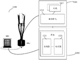
Fig. 1 is a schematic diagram of a possible application scenario of an embodiment of the present application. In fig. 1, a satellite may implement wide area coverage as an access network device, and in this scenario, a protocol stack compatible with existing protocols may be employed. In some examples, the access network device or the entity apparatus implementing the function of the access network device may be disposed on a satellite, and the satellite is not only used for implementing the transceiving of signals with the terminal device, but also used for implementing other functions of the access network device. In other examples, the access network device or the entity apparatus implementing the function of the access network device may be disposed on the ground, the satellite is only used to implement relay or transparent transmission of signals between the access network device and the terminal device, and the access network device disposed on the ground implements other functions of the access network device.
Satellite communication systems can be classified into a geostationary orbit (GEO) system, a medium orbit (MEO) system, and a low orbit (LEO) satellite communication system according to the orbital altitude of the satellite. The low earth orbit satellite has the advantages of small data propagation delay and power loss, low transmission cost, global coverage and the like, and becomes a focus of attention.
In a random access procedure specified by a communication protocol, a terminal device may send a random access signal selected from a designated set to an access network device, where the random access signal includes a preamble sequence, and the access network device obtains uplink timing by detecting a position of the preamble sequence. Timing information including uplink timing is then transmitted to the terminal device.
However, the transmission distance of satellite communication is far, the radius of the beam cell of the satellite communication system is larger than that of the ground cell, so that larger maximum round-trip transmission delay difference exists between users of the cell, which puts different requirements on the design of random access signals from the ground cell, for example, a longer random access preamble sequence needs to be used.
It should be noted that the solution of the embodiment of the present application is applicable to a satellite communication scenario, but is not limited to the satellite communication scenario, and for example, the solution may be applied to a terrestrial communication cell with a large cell radius or other types of communication cells.
Fig. 2 shows a schematic diagram of a random access signal in the time domain. Herein, the random access signal may also be referred to as a random access preamble sequence, wherein the random access signal includes a Cyclic Prefix (CP), a preamble sequence (preamble), and a Guard Time (GT). The cyclic prefix is used for compensating channel delay and solving intersymbol interference. The preamble sequence is generated using a ZC sequence. Among them, the ZC sequence is called a Zadoff-Chu sequence, and may be called a generalized chirp-like (generalized chirp-like) sequence. The guard interval is used to prevent interference between the data of the current frame and the data of the next frame. In some examples, the guard interval may not be filled with data, or for convenience of data processing, a segment of useless data may be filled in the guard interval portion. The time length of the CP is usually greater than the maximum round-trip transmission delay difference of the cell, and the time length of the GT is also greater than the maximum round-trip transmission delay difference of the cell.
The generation method of the ZC sequence may be represented by the following formula:

wherein x isu(N) denotes a root number u and a length NzcU represents the root number of the ZC sequence, NzcDenotes the ZC sequence length.
As an example, table 1 shows parameters of a preamble format (preamble format) of a low frequency band below 6GHz, and table 2 shows system parameters supported by the preamble format in table 1. Wherein, TCPIndicating the time length of the cyclic prefix, TSEQDenotes the time length of the preamble sequence,. DELTA.fRAIndicating the subcarrier spacing, TCPAnd TSEQTime unit of (1) is TsThe PRACH indicates a Physical Random Access Channel (PRACH) of 1/(1500 × 2048) ═ 32.6 ns. The guard time refers to the length of time of the guard interval.
TABLE 1
| Preamble formats | TCP | TSEQ | ΔfRA(kHz) |
| 0 | 3168 | 24576 | 1.25 |
| 1 | 21024 | 2*24567 | 1.25 |
| 2 | 4668 | 4*24576 | 1.25 |
| 3 | 3168 | 4*6144 | 5 |
TABLE 2


In existing communication protocols, a ZC sequence is generally used to generate a preamble sequence. Multiple preamble sequences based on the same root sequence can be generated by cyclically shifting a ZC sequence. But with a cyclic shift offset NCSNeed to pass throughAnd (6) counting. If N is presentCSIf the size is too large, the total number of preamble sequences that can be generated by each root sequence is reduced, so that more root sequences are needed to meet the requirement of the total number of preamble sequences of the cell. If N is presentCSIf the size of the peak is too small, the access network device may fall into the detection window of other users when detecting the correlation peak of a certain terminal device, and thus a collision occurs. Cyclic shift offset value NCSThe following conditions are satisfied:

where r denotes the cell radius, τdsRepresenting the maximum delay spread, NZCDenotes the length of the ZC sequence, TsymDenotes the duration of a preamble symbol, ngIndicating the number of guard samples appended by the receiver pulse-shaping filter.
As can be seen from equation (2), the larger the cell radius is, the required cyclic shift offset value NCSThe larger. For example, assuming that a communication system specifies that a single cell needs to contain 64 available preamble sequences, in the case that the maximum radius of the cell supported by the communication system is 102km, the 64 preamble sequences of the cell can only be generated by using 64 different root sequences, and cyclic shift cannot be used to generate the preamble sequences. The radius of the beam cell of the satellite communication system is usually larger than that of the terrestrial cell, and therefore, more root sequences cannot be generated by cyclic shift. And the number of users accessing a single satellite cell may be more than that of the terrestrial cell, and the process of detecting multi-user access by the access network equipment becomes very complicated if the existing preamble sequence format is not improved.
Fig. 3 is a diagram illustrating detection of a random access preamble sequence. As shown in fig. 3, there is a round-trip transmission delay difference between a near-point user and a far-point user, and the access network device detects a correlation peak corresponding to the user through an observation window. For random access signal design, the time length (T) of the CP of the random access signalCP) Guard interval of random access signal larger than maximum round-trip transmission delay difference in cellIt also needs to be larger than the maximum round-trip transmission delay difference in the cell. Otherwise, uplink timing errors of the access network equipment to the cell may be caused. Thus, if the maximum round-trip transmission delay difference in the beam cell is greater than TCPIt is necessary to increase the duration of the CP, preamble sequence and GT of its random access signal. For satellite communication systems, the round-trip delay variation within a beam cell may be greater than the duration of the maximum cyclic prefix of a preamble sequence specified in existing communication protocols. The existing preamble sequence formats may not meet the access requirements of the beam cells in the satellite communication system. For example, for a low-orbit satellite with an orbit height of 700 kilometers (km), the diameter of a beam cell is 200km, and when the user minimum elevation angle is 10 °, the round-trip propagation delay difference of an edge cell of the satellite is 1.3 milliseconds (ms). The round-trip delay difference is larger than the maximum CP time length of the prior preamble sequence.
In addition, for terrestrial cells, TCPTypically less than the duration of a preamble symbol, and for a satellite communication cell, TCPAnd therefore, for a satellite communication cell, an access preamble detection algorithm of the terrestrial communication system needs to be adjusted to enable the detection algorithm to detect the timing with the maximum round trip transmission delay difference larger than one preamble symbol.
In order to solve the above problem, an embodiment of the present application provides a communication method, where a preamble sequence in the communication method includes K first symbols and Q second symbols, where the K first symbols may be the same symbols or different symbols. The Q second symbols are mutually the same symbols, or are mutually repeated symbols. In the embodiment of the present application, the number, distribution, and padding design of the first symbol and the second symbol may be designed to improve the detection efficiency of detecting the random access signal.
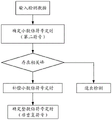
Fig. 4 is a schematic diagram of a random access method according to an embodiment of the present application. As shown in fig. 4, the method includes the following steps.
S401, the terminal equipment receives the broadcast signal.
For example, the broadcast signal may be a broadcast signal transmitted by an access network device. The broadcast signal includes random access configuration information. The random access configuration information may be configuration information of a random access signal, so that the terminal device sends the random access signal according to the random access configuration information.
S402, the terminal device sends a random access signal, a preamble sequence in the random access signal includes K first symbols and Q second symbols, wherein the first symbols and the second symbols are mutually different symbols, K, Q is an integer greater than or equal to 1, and K + Q is NSEQ,NSEQThe number of symbols included for the preamble sequence.
The first symbol and the second symbol are different symbols, which may mean that any one of the K first symbols is different from any one of the Q second symbols. The above-mentioned inequality may mean that information carried in the first symbol and the second symbol is not the same, or that a ZC sequence used to generate the first symbol is not the same as a ZC sequence used to generate the second symbol, or that a ZC sequence used to fill the first symbol is different from a ZC sequence used to fill the second symbol.
Wherein the random access signal includes a CP, the preamble sequence, and a GT. Alternatively, the random access signal including the first symbol and the second symbol may also be referred to as a non-repeated random access preamble sequence.
In the embodiment of the application, the first symbol and the second symbol which are different from each other are arranged in the preamble sequence of the random access signal, so that the detection efficiency of the random access signal can be improved, and the access requirement of a satellite communication system or other communication systems can be met.
Optionally, in some examples, the Q second symbols are the same symbols. That is, the information carried in the Q second symbols is the same, or the ZC sequences used for generating the Q second symbols are the same sequence, or the ZC sequences used for padding the Q second symbols are the same sequence. The Q second symbols may be used to determine fractional symbol timing. The decimal symbol timing may refer to a decimal portion of the timing when the preamble symbol is used as a timing unit. For example, in the case where the uplink timing exceeds one preamble symbol, the Q second symbols may be used to determine a fractional symbol portion of the timing. The decimal symbol timing may be determined by using a classical access detection algorithm of a terrestrial communication system, or may also be determined by using other detection methods.
Optionally, in some examples, the K first symbols may be the same symbols as each other, or the K first symbols may also be different symbols from each other. Alternatively, the K first symbols may be generated from the same ZC sequence or different ZC sequences. The K first symbols may be used to determine an integer multiple symbol portion of the timing. Alternatively, the K symbols are also used to distinguish between multiple users.
Optionally, in some examples, the padding of the CP may be associated with the preamble sequence. For example, the CP may be padded with a partial sequence of the length as long as the CP, which is the last of the preamble sequence. For example, if TCP=2.80ms,TSEQThe CP may be sequentially padded with data of 2.80ms length, i.e., 3.60ms to 6.40ms of the preamble sequence part, 6.40 ms.
Optionally, in some examples, the GT portion may not be populated with any data, or may be populated with a piece of data that is not useful, for convenience of data processing, or is not limited to being populated using other means.
Fig. 5 is a flowchart illustrating detecting uplink timing according to an embodiment of the present application. FIG. 5 is for TCPGreater than the duration of one preamble symbol. Wherein T isCPAn integer part of the number of symbols and a fractional part of the number of symbols may be included. Or, TCPA non-integer multiple of the number of symbols may be included. As shown in fig. 5, when performing uplink timing, an access detection algorithm may be used to detect a second symbol first to determine a decimal symbol timing; then after compensating for the fractional timing, determining the integer multiple by detecting the position of the first symbolThe symbol timing of (c).
In the terrestrial communication system, the maximum round-trip transmission delay difference is small, so the length of the preamble signal in the random access signal is short, and the symbols included in the preamble sequence are all the same symbols. In some examples of the present application, in order to adapt to the requirements of the satellite communication system specification, the total length of the preamble sequence may be increased by increasing the number of symbols included in the preamble sequence in the random access signal.
Optionally, in some examples, the subcarrier spacing employed by the random access signal may be Δ fRA1.25kHz, the duration of a symbol in a random access signal can be denoted as Tsym=1/ΔfRA0.8 ms. Wherein, Δ fRAIndicating the subcarrier spacing, TsymIndicating the length of one symbol in the random access signal. Here, the symbols in the random access signal may also be referred to as preamble symbols.
Fig. 6 is a schematic diagram of a random access signal in a time domain according to another embodiment of the present application. As shown in fig. 6, the random access signal includes a CP, a preamble sequence, and a GT. Wherein, TCP、TSEQ、TGTRespectively, the time lengths of the CP, the preamble sequence, and the GT. The embodiment of the application designs a filling mode of a ZC sequence in a random access signal and time lengths of a CP, a leader sequence and a GT in the random access signal based on a design criterion of a random access leader sequence and a leader sequence format scheme, and determines the number and distribution form of a first symbol and a second symbol in the leader sequence, so as to achieve the purposes of reducing the detection complexity of access network equipment and improving the detection efficiency of the random access signal.
With continued reference to fig. 6, in one example, the total length T of the random access signal may be madeRAIs an integer multiple of the subframe length. Wherein, TRA=TCP+TSEQ+TGTOne subframe length may be, for example, 1 ms. The length of the CP may be expressed as Wherein the content of the first and second substances,
 an integer part for representing the number of symbols,
 for the fractional part of the number of symbols.
 Is an integer greater than or equal to 0,
 is decimal, and
 length of leader sequence TSEQ=NSEQ×TsymWherein N isSEQIs a positive integer. Length of GT
 Wherein the content of the first and second substances,
 an integer part for representing the number of symbols,
 for the fractional part of the number of symbols.
 Is an integer greater than or equal to 0,
 is decimal, and
 alternatively, the intervals of the CP, the preamble sequence and the GT may each be greater than the duration T of one preamble symbolsym。
In one possible implementation, the number of first symbols and second symbols may be made equal or similar as possible. The K first symbols may be the same symbols or different symbols, and the Q second symbols may be the same symbols. For example, K ═ Q, or K ═ 1. Alternatively, in another example, the above design concept may also be understood that, in a case where there are other boundary conditions, the number of the first symbols and the number of the second symbols may be as close as possible while satisfying the other boundary conditions.
For example, when TCP>TsymThe uplink timing estimation can be performed using a non-repeating random access preamble sequence. The detection scheme utilizes the first symbol to perform integer multiple symbol timing and utilizes the second symbol to perform decimal multiple symbol timing, and the two symbols simultaneously provide detection gain for a final timing result, and the number of the two symbols in the sequence is balanced as much as possible during design. The leader sequence includes NSEQA preamble symbol of which there are K first symbols, and Q (Q ═ N)SEQ-K) repeated symbols. The magnitudes of K and Q can be made as close as possible, such as when NSEQWhen 4, 2 is the number of the first symbols.
In the embodiment of the present application, by designing the number of the first symbol and the second symbol in the preamble sequence of the random access signal, the detection performance of the random access signal can be optimized.
Optionally, in some examples, the K first symbols and the Q second symbols meet at least one of the following conditions:
(1) the above-mentioned
(2)
(3)TSEQ≥TCP≥ΔTRTD,TSEQ≥TGT≥ΔTRTD;
Wherein the content of the first and second substances, indicating the cyclic prefix packetInteger part of the number of symbols enclosed, TSEQRepresents the time length, T, of the preamble sequenceCPRepresents the time length, T, of the cyclic prefixGTRepresents the time length of the guard interval, Δ TRTDRepresenting the maximum round-trip transmission delay difference within the cell.
Wherein the above condition (1) includes The condition (3) can be understood that the time lengths of the CP, the preamble sequence and the GP need to satisfy the constraint condition of the maximum round-trip transmission delay difference of the cell. When the above conditions are satisfied, the detection performance gain of the random access signal can be improved.
In some examples, the K first symbols may be the same symbol in a case where the above condition is satisfied.
In some examples, K may be a maximized number that satisfies the above condition. Or it can be understood that in the case that the above condition is satisfied, the number of the first symbols is increased as much as possible, which will improve the detection performance gain of the random access signal. In addition, in other examples, in the case that the above condition is satisfied, the number of the first symbols and the second symbols may be made as close as possible to improve the detection performance gain of the random access signal. Wherein, the satisfying of the above condition may refer to satisfying one or more of the above conditions or satisfying all of the above conditions.
Fig. 7 is a distribution diagram of random access preamble sequence formats according to the above-mentioned conditions according to an embodiment of the present application. Assuming that the orbital height of the satellite is 700km, the user minimum elevation angle is 10 °, and the radius of the beam cell is 200 km. Maximum round trip delay RTD of edge cell of systemmax14.42ms, the minimum round trip delay RTDmin11.82ms, symbol length Tsym0.8ms, the maximum round trip transmission delay difference Δ TRTD=RTDmax-RTDmin=2.6ms。ΔTRTD>Tsym。
As shown in fig. 7, the random access preamble sequence includes a CP,A leader sequence and a GT. Wherein, TCP=2.80ms,TSEQ=6.40ms,TGT2.80ms, which satisfies Δ T in the beam cellRTDThe constraint of (2). In this case, the CP and GT have a time length of 3.5 preamble symbols, and the preamble sequence includes 8 preamble symbols. The 1 st and 5th preamble symbols of the preamble sequence are used to fill the first symbol and the remaining preamble symbols of the preamble sequence are used to fill the second symbol. The above format distribution satisfies the above condition from item (1) to item (3), where K is 2 and Q is 6. In addition, the CP may also be used to fill the second symbol. Alternatively, the second symbols may be the same symbols, and the first symbols may be the same or different symbols.
Alternatively, the selection of K may be a maximized number in case that the above condition is satisfied, which will improve the detection performance of the random access signal. For example, fig. 8 is a schematic distribution diagram of a random access preamble sequence according to another embodiment of the present application. The basic parameters of the application environment of fig. 8 are the same as those of fig. 7. However, fig. 8 only designs one first symbol, i.e., K is 1, on the basis of satisfying the above conditions. In particular, TCP=2.80ms,TSEQ=6.40ms,TGT2.80 ms. The CP and GT have a time length of 3.5 preamble symbols and the preamble sequence comprises 8 preamble symbols. The 1 st preamble symbol of the preamble sequence is used to fill the first symbol and the remaining preamble symbols of the preamble sequence are used to fill the second symbol. The CP may also be used to fill the second symbol. Alternatively, the second symbols may be the same symbols, and the first symbols may be the same or different symbols.
Fig. 9 is a diagram illustrating detection performance of the random access preamble sequence of fig. 7 corresponding to fig. 8. As shown in fig. 9, the abscissa represents the signal-to-noise ratio (SNR) of the received signal, and the ordinate represents the probability of false detection (error detection rate) of random access. In the case of a given signal-to-noise ratio, the probability of false detection is smaller when using the random access signal format of 2 first symbols than when using the random access signal format of only 1 first symbol, and thus the random access preamble sequence of fig. 7 obtains a larger detection performance gain by increasing the number of K.
The embodiment of the application also provides a design scheme of a non-repeated random access preamble format. According to the design scheme, through designing the ZC sequences for generating the first symbol and the second symbol, more leader sequences can be obtained by using the ZC sequences with different roots as few as possible.
In some examples, the K symbols are the same symbol, the first symbol is according to the u-th symbol in the first set1Generated from the u-th symbol in the second set2Generated by ZC sequences, wherein the first set comprises NU1ZC sequences of different roots, the second set comprising NU2ZC sequences of different roots, wherein the intersection of the first set and the second set is an empty set, NU1,NU2Is an integer of 1 or more, 1 is not less than u1≤NU1,1≤u2≤NU2。
In this embodiment of the present application, in a case where K first symbols are the same symbol, the above design scheme designs ZC sequences that generate the first symbol and the second symbol, so that more preamble sequences can be obtained with as few ZC sequences of different roots as possible, so as to improve random access efficiency.
As a specific example, the above-mentioned manner of generating the non-repeating random preamble sequence may include the following steps.
(1) Dividing all available ZC sequences of different roots in a cell into U1And U2And in the two sets, each ZC sequence corresponds to a different root, and each ZC sequence corresponds to a root sequence number. Set U1Is used only for generating the first symbol, set U2The ZC sequence of (1) is used only for generating the second symbol.
(2) If a terminal device in a cell wants to initiate a random access procedure, a preamble sequence to be used may be generated in the following manner: selecting the U-th from the set U11The ZC sequences are used for generating K first symbols, the K first symbols are the same symbols, and the u th symbols are all used1And generating ZC sequences. Selecting the U-th from the set U22The ZC sequences are used for generating Q second symbols, whereinQ second symbols are the same symbols, all using the u-th symbol2And generating ZC sequences. Parameter { u }1,u2Determining a leader sequence together as long as u is selected by the terminal device1、u2With one difference, a different leader sequence is considered to be used. Wherein, in some examples, due to the set U1And set U2U is different because each ZC sequence in the set has a different root number1、u2Or replaced by the root sequence number of the ZC sequence, i.e. the root sequence number is used to represent and distinguish ZC sequences of different roots.
If the set U is generated in the manner of the preamble sequence described above1Containing NU1Root sequence, set U2Containing NU2The number of the total generated leader sequences is NU1×NU2And (4) respectively. For example, if a single cell requires 64 preamble sequences. Considering the case of using the same symbol in the preamble sequence, a total of 64 ZC sequences with different roots are required because more preamble sequences cannot be generated using a simple cyclic shift method for a satellite communication system. If the preamble sequence is formed by the first symbol and the second symbol, for example, N may be setU1=8,NU2Thus, only 16 ZC sequences of different roots are needed to generate 64 preamble sequences, which can reduce the required ZC sequences of different roots.
In the embodiment of the application, according to the characteristics of a non-repetitive random access sequence detection algorithm, the ZC sequence is used for filling the first symbol and the second symbol, so that different root sequences can be utilized as few as possible to generate a leader sequence to distinguish different users, and the random access efficiency is effectively improved.
In some examples, the K first symbols are mutually different symbols, the K first symbols being generated according to ZC sequences in K third sets, each of the K third sets including a symbol based on a u-th symbol in the first set1M ZC sequences generated by cyclic shift of ZC sequences, the second symbol is according to the u-th symbol in the second set2Generated by ZC sequences, wherein the first ZC sequence is a first ZC sequenceThe set comprises NU1ZC sequences of different roots, the second set comprising NU2ZC sequences of different roots, wherein the intersection of the first set and the second set is a null set, and u is more than or equal to 11≤NU1,1≤u2≤NU2M is an integer of 1 or more; the K third sets meet the following condition: CSi={i×NCS,1,i×NCS,2,…,i×NCS,M},i=1,…,K,CSiRepresenting a set of M cyclic offsets corresponding to M ZC sequences included in the ith third set, wherein i is more than or equal to 1 and less than or equal to K; the K first symbols are in one-to-one correspondence with the K third sets, wherein the ith first symbol uses an offset in the ith third set to be i × Ncs,mM is more than or equal to 1 and less than or equal to M generated by the ZC sequence.
In the embodiment of the present application, when the K first symbols are different symbols, the cyclic offset of the ZC sequence used by the K first symbols is conditionally limited, so that, when the K first symbols are generated by using ZC sequences with the same root and different cyclic offsets, the influence on the detection performance of the preamble sequence due to the increase of the maximum round-trip transmission delay can be reduced or eliminated, and thus, more preamble sequences can be obtained by using ZC sequences with different roots as few as possible, so as to improve the random access efficiency.
Taking the non-repeated random preamble sequence shown in fig. 7 as an example, assuming that K is 2 and the two first symbols are different, the above manner of generating the non-repeated random preamble sequence may include the following steps.
(1) Dividing ZC sequences of different roots available in a cell into U1And U2And each ZC sequence corresponds to a root sequence number. Set U1Is used only for generating the first symbol, set U2The ZC sequence of (1) is used only for generating the second symbol. Wherein the first symbol is using the set U1The ZC sequence of (a) is cyclically shifted to generate a ZC sequence, and the ZC sequence used for the second symbol has no cyclic shift.
(2) If a terminal device in a cell wants to initiate a random access procedure, the following procedure can be adoptedThe used preamble sequence is generated: from the set U1To select u (th)1A ZC sequence in which the first symbol has sequence number u1Cyclic offset of NCS,mThe second first symbol adopts a sequence number u1Cyclic offset of 2NCS,mGenerating the ZC sequence of (1). From the set U2To select u (th)2The ZC sequences are used for generating Q second symbols, wherein the Q second symbols are the same symbol and all use the u < th > symbol2And generating ZC sequences. Thus, the parameter { N can be consideredCS,m,u1,u2Determine a preamble sequence together as long as the user selects NCS,m,u1,u2With a difference, different random access preamble sequences can be considered to be used.
Here, the first symbols may be considered to be generated according to ZC sequences in K third sets, where the K third sets correspond to the K first symbols in a one-to-one manner. Each third set includes a u-th set based on the first set1And the ZC sequences are subjected to cyclic offset to generate M ZC sequences. When K is 2, the third set satisfies the following condition: CS1={NCS,1,NCS,2,…,NCS,M},CS2={2×NCS,1,2×NCS,2,…,2×NCS,M}。CS1And CS2Respectively representing sets of M cyclic offsets corresponding to M ZC sequences included in the first and second third sets. Said first symbol is selected from a first third set with an offset of NCS,mThe second first symbol is selected from the second third set with an offset of 2NCS,mM is more than or equal to 1 and less than or equal to M.
Optionally, in a case where K is 2 or greater than 2, the K third sets satisfy the following condition: CSi={i×NCS,1,i×NCS,2,…,i×NCS,M},i=1,…,K,CSiRepresenting a set of M cyclic offsets corresponding to M ZC sequences included in the ith third set, wherein i is more than or equal to 1 and less than or equal to K; the K first symbols are in one-to-one correspondence with the K third sets, wherein the ith first symbolNumber is using an offset in the ith third set of i Ncs,mM is more than or equal to 1 and less than or equal to M generated by the ZC sequence.
Wherein, in some examples, due to the set U1And set U2U is different because each ZC sequence in the set has a different root number1、u2Or replaced by the root sequence number of the ZC sequence, i.e. the root sequence number is used to represent and distinguish ZC sequences of different roots.
According to the above preamble sequence generation method, if set U1Comprising NU1Root number, set U2Comprising NU2Each third set comprises M ZC sequences, and the number of usable leader sequences is M multiplied by NU1×NU2And thus the number of available preamble sequences is greatly increased.
Optionally, in some examples, the third set can reduce or eliminate an impact on the detection performance of the preamble sequence due to a large maximum round-trip transmission delay difference when at least one of the following conditions is satisfied. The following conditions apply to the case where K is 2 and also to the case where K is greater than 2.
(1) Set CS1And CS2Any two elements of (a) are different from each other;
(2) set CS1The sum of any two different elements in the set CS not belonging to2。
Optionally, in other examples, the third set can reduce or eliminate the influence on the detection performance of the preamble sequence due to the large maximum round-trip transmission delay difference when at least one of the following conditions is satisfied. The following condition applies to the case where K is 2, and also to the case where K is greater than 2.
(1) Set CSiAnd set CSjWherein any two elements in (1) are different, wherein CSiRepresenting a set of M cyclic offsets corresponding to M ZC sequences included in the ith third set, wherein i is more than or equal to 1 and less than or equal to K; CSjRepresenting a set of cyclic offsets corresponding to M ZC sequences in the jth third set, wherein j is more than or equal to 1 and less than or equal to K, and i is not equal to j;
(2) set CSiDoes not belong to the set CSj。
Alternatively, in the case where the above condition is satisfied, in the case where K is 2 or more than 2, even if the preamble sequence selects the same u1And u2The N and N are mixed together according to different time differences, and the access network equipment can also distinguish different N according to a detection algorithmCS,m。
Alternatively, the selection manner of the ZC sequence for generating the first symbol and the second symbol in the embodiments of the present application is not limited to the above example. The ZC sequence for generating the first symbol and the second symbol may also be selected in other manners, which is not limited in this embodiment of the present application.
In the embodiment of the application, a plurality of users competing for access can be distinguished by designing the K first symbols according to the characteristics of a non-repetitive random access sequence detection algorithm. The method of superposing the specific cyclic shift offset on the root sequence of the first symbol ensures that the design scheme can distinguish multiple users by using different root sequences as few as possible, thereby effectively improving the access efficiency.
Fig. 10 is a diagram illustrating detection performance of a non-repeated random access preamble sequence according to an embodiment of the present application. Fig. 10 shows detection performance of a non-repeated random access preamble sequence in a multi-user scenario. In fig. 10, the non-repeated random access preamble sequence shown in fig. 7 is used. FIG. 10 shows the number of users N user1, 2, 4, 8, and the detection performance of the preamble sequence. Parameters u used by the plurality of users1,u2Are identical, with the difference being the cyclic offset N for each usercs,mDifferent. And under the condition that the random access preamble signals of different users are transmitted by using the same time-frequency resource and almost reach the access network device at the same time, the probability of error detection of different numbers of users by the access network device is shown in fig. 10.
The abscissa of fig. 10 represents the snr of the received signal, and the ordinate represents the probability of false detection of the access signals of different numbers of users by the access network equipment, if and only if the uplinks of all users are correctly detectedThe sync position is determined to be detected correctly. As can be seen from the error detection probability curves corresponding to different numbers of users in fig. 10, the access network device can distinguish and detect different users and corresponding uplink synchronization positions. Thus, as can be seen in FIG. 10, even though different users have selected the same u1And u2The preamble sequences are mixed together according to different time differences, and the access network equipment can also distinguish different N according to a detection algorithmCS,m。
The random access method according to the embodiment of the present application is described in detail above with reference to fig. 1 and 10. The apparatus according to the embodiment of the present application is described in detail below with reference to fig. 11 to 13.
Fig. 11 is a schematic structural diagram of a terminal device according to an embodiment of the present application. The terminal device may be adapted to perform the functions of the terminal device in the above-described method embodiments. For convenience of explanation, fig. 11 shows only main components of the terminal device. As shown in fig. 11, the terminal device 1100 includes a processor, a memory, a control circuit, an antenna, and an input-output means. The processor is mainly configured to process the communication protocol and the communication data, control the entire terminal device, execute a software program, and process data of the software program, for example, to support the terminal device to perform the actions described in the above method embodiments, such as sending a random access signal. The memory is primarily used for storing software programs and data. The control circuit is mainly used for converting baseband signals and radio frequency signals and processing the radio frequency signals. The control circuit and the antenna together, which may also be called a transceiver, are mainly used for transceiving radio frequency signals in the form of electromagnetic waves. Input and output devices, such as touch screens, display screens, keyboards, etc., are used primarily for receiving data input by a user and for outputting data to the user.
When the terminal device is started, the processor can read the software program in the storage unit, interpret and execute the instruction of the software program, and process the data of the software program. When data needs to be sent wirelessly, the processor outputs a baseband signal to the radio frequency circuit after performing baseband processing on the data to be sent, and the radio frequency circuit performs radio frequency processing on the baseband signal and sends the radio frequency signal outwards in the form of electromagnetic waves through the antenna. When data is sent to the terminal equipment, the radio frequency circuit receives radio frequency signals through the antenna, converts the radio frequency signals into baseband signals and outputs the baseband signals to the processor, and the processor converts the baseband signals into the data and processes the data.
Those skilled in the art will appreciate that fig. 11 shows only one memory and one processor for ease of illustration. In an actual terminal device, there may be multiple processors and multiple memories. The memory may also be referred to as a storage medium or a storage device, and the like, which is not limited in this embodiment of the present application.
As an alternative implementation manner, the processor may include a baseband processor and/or a central processing unit, where the baseband processor is mainly used to process the communication protocol and the communication data, and the central processing unit is mainly used to control the whole terminal device, execute a software program, and process data of the software program. The processor of fig. 11 may integrate the functions of the baseband processor and the central processing unit, and those skilled in the art will understand that the baseband processor and the central processing unit may also be independent processors, and are interconnected through a bus or the like. Those skilled in the art will appreciate that the terminal device may include a plurality of baseband processors to accommodate different network formats, the terminal device may include a plurality of central processors to enhance its processing capability, and various components of the terminal device may be connected by various buses. The baseband processor can also be expressed as a baseband processing circuit or a baseband processing chip. The central processing unit can also be expressed as a central processing circuit or a central processing chip. The function of processing the communication protocol and the communication data may be built in the processor, or may be stored in the storage unit in the form of a software program, and the processor executes the software program to realize the baseband processing function.
In the embodiment of the present application, an antenna and a control circuit having a transceiving function may be regarded as the transceiving unit 1101 of the terminal device 1100, for example, for supporting the terminal device to perform a receiving function and a transmitting function as described in part of fig. 4. The processor having the processing function is considered as the processing unit 1102 of the terminal device 1100. As shown in fig. 11, the terminal device 1100 includes a transceiving unit 1101 and a processing unit 1102. A transceiver unit may also be referred to as a transceiver, a transceiving device, etc. Optionally, a device for implementing a receiving function in the transceiving unit 1101 may be regarded as a receiving unit, and a device for implementing a sending function in the transceiving unit 1101 may be regarded as a sending unit, that is, the transceiving unit 1101 includes a receiving unit and a sending unit, the receiving unit may also be referred to as a receiver, an input port, a receiving circuit, and the like, and the sending unit may be referred to as a transmitter, a sending circuit, and the like.
The processor 1102 may be configured to execute the instructions stored in the memory, so as to control the transceiver unit 1101 to receive and/or transmit signals, thereby implementing the functions of the terminal device in the above-described method embodiments. As an implementation manner, the function of the transceiving unit 1101 may be considered to be implemented by a transceiving circuit or a dedicated chip for transceiving.
Fig. 12 is a schematic structural diagram of an apparatus 1200 according to an embodiment of the present disclosure. Such as a schematic diagram of the structure of the base station. As shown in fig. 12, the apparatus 1200 may be adapted for use in the application environment described in fig. 1 or other portions of the embodiments of the present application. The access network equipment may include one or more radio frequency units, such as a Remote Radio Unit (RRU) 1201 and one or more baseband units (BBUs) (also referred to as digital units, DUs) 1202. The RRU1201 may be referred to as a transceiver unit, transceiver, transceiving circuitry, or transceiver, etc., which may include at least one antenna 1211 and a radio frequency unit 1212. The RRU1201 is mainly used for transceiving radio frequency signals and converting the radio frequency signals to baseband signals, for example, for receiving random access signals or transmitting broadcast signals. The BBU1202 is mainly used for performing baseband processing, controlling a base station, and the like. The RRU1201 and the BBU1202 may be physically disposed together or may be physically disposed separately, that is, distributed base stations.
The BBU1202 is a control center of a base station, and may also be referred to as a processing unit, and is mainly used for performing baseband processing functions, such as channel coding, multiplexing, modulation, spreading, and the like. For example, the BBU (processing unit) may be configured to control the base station to perform the operation procedure related to the access network device in the above method embodiment.
In an example, the BBU1202 may be formed by one or more boards, and the boards may collectively support a radio access network (e.g., an LTE network) of a single access system, or may respectively support radio access networks of different access systems. The BBU1202 also includes a memory 1221 and a processor 1222. The memory 1221 is used to store necessary instructions and data. For example, the memory 1221 stores preset information, a codebook, and the like in the above-described embodiment. The processor 1222 is configured to control the base station to perform necessary actions, for example, to control the base station to perform the operation procedure related to the access network device in the above method embodiment. The memory 1221 and the processor 1222 may serve one or more boards. That is, the memory and processor may be provided separately on each board. Multiple boards may share the same memory and processor. In addition, each single board can be provided with necessary circuits.
Optionally, the apparatus 1200 may be disposed on a satellite, or may be disposed in a ground station, which is not limited in this embodiment.
Fig. 13 shows a schematic structural diagram of a communication apparatus 1300. The apparatus 1300 may be used to implement the methods described in the above method embodiments, and reference may be made to the description of the above method embodiments. The communication apparatus 1300 may be a chip, an access network device (e.g., a base station), a terminal device or other access network device, etc.
The communications apparatus 1300 includes one or more processors 1301. The processor 1301 may be a general purpose processor, a special purpose processor, or the like. For example, a baseband processor, or a central processor. The baseband processor may be used to process communication protocols and communication data, and the central processor may be used to control a communication device (e.g., a base station, a terminal, or a chip), execute a software program, and process data of the software program. The communication device may include a transceiving unit to enable input (reception) and output (transmission) of signals. For example, the communication device may be a chip, and the transceiving unit may be an input and/or output circuit of the chip, or a communication interface. The chip can be used for a terminal or a base station or other access network equipment. As another example, the communication device may be a terminal or a base station or other access network equipment, and the transceiver unit may be a transceiver, a radio frequency chip, or the like.
The communication apparatus 1300 includes one or more processors 1301, and the one or more processors 1301 may implement the method of accessing a network device or a terminal device in the embodiment shown in fig. 4.
In one possible design, the communications apparatus 1300 includes means (means) for generating random access signals, and means (means) for transmitting random access signals. The functions of means for generating random access signals and means for transmitting random access signals may be implemented by one or more processors. The random access signal may be generated, for example, by one or more processors, and transmitted through a transceiver, or an interface of an input/output circuit, or chip. The random access signal may be referred to in the related description of the above method embodiments.
In one possible design, the communications apparatus 1300 includes means (means) for receiving a random access signal, and means (means) for detecting the random access signal. The method for receiving and detecting the random access signal can be referred to the related description in the above method embodiments. The random access signal may be received, for example, by a transceiver, or an interface of an input/output circuit, or chip, and detected by one or more processors.
Optionally, the processor 1301 may also implement other functions in addition to implementing the method of the embodiment shown in fig. 4.
Optionally, in one design, the processor 1301 may execute instructions to enable the communication apparatus 1300 to perform the method described in the above method embodiment. The instructions may be stored in whole or in part in the processor, such as the instruction 1303, or in whole or in part in the memory 1302 coupled to the processor, such as the instruction 1304, or may collectively cause the communication apparatus 1300 to execute the method described in the above method embodiment through the instructions 1303 and 1304.
In yet another possible design, communications apparatus 1300 may also include circuitry that may implement the functionality of the access network device or the terminal device in the foregoing method embodiments.
In yet another possible design, the communication device 1300 may include one or more memories 1302 having instructions 1304 stored thereon, which are executable on the processor, so that the communication device 1300 performs the methods described in the above method embodiments. Optionally, the memory may further store data therein. Instructions and/or data may also be stored in the optional processor. For example, the one or more memories 1302 may store the corresponding relationships described in the above embodiments, or the related parameters or tables mentioned in the above embodiments, and the like. The processor and the memory may be provided separately or may be integrated together.
In yet another possible design, the communications apparatus 1300 may further include a transceiver 1305 and an antenna 1306. The processor 1301 may be referred to as a processing unit and controls a communication apparatus (terminal or base station). The transceiver 1305, which may be referred to as a transceiver, a transceiving circuit, a transceiver, or the like, is configured to implement transceiving function of a communication device through the antenna 1306.
The present application also provides a communication system comprising one or more access network devices as described above, and one or more terminal devices.
It should be noted that the processor in the embodiments of the present application may be an integrated circuit chip having signal processing capability. In implementation, the steps of the above method embodiments may be performed by integrated logic circuits of hardware in a processor or instructions in the form of software. The processor may be a general purpose processor, a Digital Signal Processor (DSP), an Application Specific Integrated Circuit (ASIC), an off-the-shelf programmable gate array (FPGA) or other programmable logic device, discrete gate or transistor logic device, or discrete hardware components. The various methods, steps, and logic blocks disclosed in the embodiments of the present application may be implemented or performed. A general purpose processor may be a microprocessor or the processor may be any conventional processor or the like. The steps of the method disclosed in connection with the embodiments of the present application may be directly implemented by a hardware decoding processor, or implemented by a combination of hardware and software modules in the decoding processor. The software module may be located in ram, flash memory, rom, prom, or eprom, registers, etc. storage media as is well known in the art. The storage medium is located in a memory, and a processor reads information in the memory and completes the steps of the method in combination with hardware of the processor.
It will be appreciated that the memory in the embodiments of the subject application can be either volatile memory or nonvolatile memory, or can include both volatile and nonvolatile memory. The non-volatile memory may be a read-only memory (ROM), a Programmable ROM (PROM), an Erasable PROM (EPROM), an electrically Erasable EPROM (EEPROM), or a flash memory. Volatile memory can be Random Access Memory (RAM), which acts as external cache memory. By way of example, but not limitation, many forms of RAM are available, such as Static Random Access Memory (SRAM), Dynamic Random Access Memory (DRAM), Synchronous Dynamic Random Access Memory (SDRAM), double data rate SDRAM, enhanced SDRAM, SLDRAM, Synchronous Link DRAM (SLDRAM), and direct rambus RAM (DR RAM). It should be noted that the memory of the systems and methods described herein is intended to comprise, without being limited to, these and any other suitable types of memory.
The present application further provides a computer-readable medium, on which a computer program is stored, where the computer program, when executed by a computer, implements the random access method described in any of the above method embodiments.
The embodiment of the present application further provides a computer program product, and when executed by a computer, the computer program product implements the random access method described in any of the above method embodiments.
In the above embodiments, all or part of the implementation may be realized by software, hardware, firmware, or any combination thereof. When implemented in software, may be implemented in whole or in part in the form of a computer program product. The computer program product includes one or more computer instructions. When loaded and executed on a computer, cause the processes or functions described in accordance with the embodiments of the application to occur, in whole or in part. The computer may be a general purpose computer, a special purpose computer, a network of computers, or other programmable device. The computer instructions may be stored on a computer readable storage medium or transmitted from one computer readable storage medium to another, for example, from one website, computer, server, or data center to another website, computer, server, or data center via wire (e.g., coaxial cable, fiber optic, Digital Subscriber Line (DSL)) or wireless (e.g., infrared, wireless, microwave, etc.). The computer-readable storage medium can be any available medium that can be accessed by a computer or a data storage device, such as a server, a data center, etc., that incorporates one or more of the available media. The usable medium may be a magnetic medium (e.g., a floppy disk, a hard disk, a magnetic tape), an optical medium (e.g., a Digital Video Disk (DVD)), or a semiconductor medium (e.g., a Solid State Disk (SSD)), among others.
The embodiment of the application also provides a processing device, which comprises a processor and an interface; the processor is configured to execute the random access method in any of the above method embodiments.
It should be understood that the processing device may be a chip, the processor may be implemented by hardware or software, and when implemented by hardware, the processor may be a logic circuit, an integrated circuit, or the like; when implemented in software, the processor may be a general-purpose processor implemented by reading software code stored in a memory, which may be integrated in the processor, located external to the processor, or stand-alone.
It should be appreciated that reference throughout this specification to "one embodiment" or "an embodiment" means that a particular feature, structure or characteristic described in connection with the embodiment is included in at least one embodiment of the present application. Thus, the appearances of the phrases "in one embodiment" or "in an embodiment" in various places throughout this specification are not necessarily all referring to the same embodiment. Furthermore, the particular features, structures, or characteristics may be combined in any suitable manner in one or more embodiments. It should be understood that, in the various embodiments of the present application, the sequence numbers of the above-mentioned processes do not mean the execution sequence, and the execution sequence of each process should be determined by its function and inherent logic, and should not constitute any limitation to the implementation process of the embodiments of the present application.
Additionally, the terms "system" and "network" are often used interchangeably herein. The term "and/or" herein is merely an association describing an associated object, meaning that three relationships may exist, e.g., a and/or B, may mean: a exists alone, A and B exist simultaneously, and B exists alone. In addition, the character "/" herein generally indicates that the former and latter related objects are in an "or" relationship.
It should be understood that in the embodiment of the present application, "B corresponding to a" means that B is associated with a, from which B can be determined. It should also be understood that determining B from a does not mean determining B from a alone, but may be determined from a and/or other information.
Those of ordinary skill in the art will appreciate that the elements and algorithm steps of the examples described in connection with the embodiments disclosed herein may be embodied in electronic hardware, computer software, or combinations of both, and that the components and steps of the examples have been described in a functional general in the foregoing description for the purpose of illustrating clearly the interchangeability of hardware and software. Whether such functionality is implemented as hardware or software depends upon the particular application and design constraints imposed on the implementation. Skilled artisans may implement the described functionality in varying ways for each particular application, but such implementation decisions should not be interpreted as causing a departure from the scope of the present application.
It is clear to those skilled in the art that, for convenience and brevity of description, the specific working processes of the above-described systems, apparatuses and units may refer to the corresponding processes in the foregoing method embodiments, and are not described herein again.
In the several embodiments provided in the present application, it should be understood that the disclosed system, apparatus and method may be implemented in other ways. For example, the above-described apparatus embodiments are merely illustrative, and for example, a division of a unit is merely a logical division, and an actual implementation may have another division, for example, a plurality of units or components may be combined or integrated into another system, or some features may be omitted, or not executed. In addition, the shown or discussed mutual coupling or direct coupling or communication connection may be an indirect coupling or communication connection through some interfaces, devices or units, and may also be an electric, mechanical or other form of connection.
Units described as separate parts may or may not be physically separate, and parts displayed as units may or may not be physical units, may be located in one place, or may be distributed on a plurality of network units. Some or all of the elements may be selected according to actual needs to achieve the purpose of the solution of the embodiments of the present application.
In addition, functional units in the embodiments of the present application may be integrated into one processing unit, or each unit may exist alone physically, or two or more units are integrated into one unit. The integrated unit can be realized in a form of hardware, and can also be realized in a form of a software functional unit.
Through the above description of the embodiments, those skilled in the art will clearly understand that the present application can be implemented in hardware, firmware, or a combination thereof. When implemented in software, the functions described above may be stored on or transmitted over as one or more instructions or code on a computer-readable medium. Computer-readable media includes both computer storage media and communication media including any medium that facilitates transfer of a computer program from one place to another. A storage media may be any available media that can be accessed by a computer. Take this as an example but not limiting: computer-readable media can include RAM, ROM, EEPROM, CD-ROM or other optical disk storage, magnetic disk storage or other magnetic storage devices, or any other medium that can be used to carry or store desired program code in the form of instructions or data structures and that can be accessed by a computer. Furthermore, the method is simple. Any connection is properly termed a computer-readable medium. For example, if software is transmitted from a website, a server, or other remote source using a coaxial cable, a fiber optic cable, a twisted pair, a Digital Subscriber Line (DSL), or a wireless technology such as infrared, radio, and microwave, the coaxial cable, the fiber optic cable, the twisted pair, the DSL, or the wireless technology such as infrared, radio, and microwave are included in the fixation of the medium. Disk and disc, as used herein, includes Compact Disc (CD), laser disc, optical disc, Digital Versatile Disc (DVD), floppy disk and blu-ray disc where disks usually reproduce data magnetically, while discs reproduce data optically with lasers. Combinations of the above should also be included within the scope of computer-readable media.
In short, the above description is only a preferred embodiment of the present disclosure, and is not intended to limit the scope of the present disclosure. Any modification, equivalent replacement, improvement and the like made within the spirit and principle of the present application shall be included in the protection scope of the present application.
Claims (24)
1. A random access method, comprising:
the terminal equipment receives a broadcast signal;
the terminal device sends a random access signal, a preamble sequence in the random access signal includes K first symbols and Q second symbols, where the first symbols and the second symbols are mutually different symbols, K, Q is an integer greater than or equal to 1, and K + Q ═ NSEQ,NSEQThe number of symbols included in the preamble sequence;
the random access signal comprises a cyclic prefix, the preamble sequence and a guard interval, and the K first symbols and the Q second symbols meet at least one of the following conditions:
the described

TSEQ≥TCP≥ΔTRTD,TSEQ≥TGT≥ΔTRTD;
Wherein, the first and the second end of the pipe are connected with each other, an integer part, T, representing the number of symbols comprised by said cyclic prefixSEQRepresents the time length, T, of the preamble sequenceCPRepresents the time length, T, of the cyclic prefixGTRepresents the time length of the guard interval, Δ TRTDRepresenting the maximum round-trip transmission delay difference within the cell.
2. The method of claim 1, wherein the Q second symbols are the same symbols.
3. The method of claim 1, wherein K is a maximized number that meets the condition.
4. A method according to any one of claims 1 to 3, wherein the K first symbols are the same symbol.
5. The method of claim 4, wherein the first symbol is according to the u (th) symbol in the first set1Generated from the u-th symbol in the second set2Generated by ZC sequences, wherein the first set comprises NU1ZC sequences of different roots, the second set comprising NU2ZC sequences of different roots, wherein the intersection of the first set and the second set is an empty set, NU1,NU2Is an integer of 1 or more, u is 1 or less1≤NU1,1≤u2≤NU2。
6. The method according to any one of claims 1 to 3, wherein the K first symbols are mutually different symbols.
7. The method of claim 6, wherein the K first symbols are generated from ZC sequences in K third sets, each of the K third sets comprising a first set based on a u-th symbol of the first set1M ZC sequences generated by cyclic shift of ZC sequences, the second symbol is according to the u-th symbol in the second set2Generated by ZC sequences, wherein the first set comprises NU1ZC sequences of different roots, the second set comprising NU2ZC sequences of different roots, wherein the intersection of the first set and the second set is a null set, and u is more than or equal to 11≤NU1,1≤u2≤NU2M is an integer of 1 or more;
the K third sets meet the following condition: CSi={i×NCS,1,i×NCS,2,…,i×NCS,M},i=1,…,K,CSiRepresenting a set of M cyclic offsets corresponding to M ZC sequences included in the ith third set, wherein i is more than or equal to 1 and less than or equal to K;
the K first symbols are in one-to-one correspondence with the K third sets, where an ith first symbol is nxn using an offset in the ith third setcs,mGenerating the ZC sequence, wherein M is more than or equal to 1 and less than or equal to M.
8. The method of claim 7, wherein the K third sets are at least one of:
set CS1And set CS2Any two elements of (a) are different from each other;
set CS1The sum of any two different elements in the set CS not belonging to2。
9. The method of any of claims 1-3, wherein a length of a cyclic prefix in the random access signal is greater than a length of one symbol.
10. A random access method, comprising:
the access network equipment sends a broadcast signal;
the access network equipment receives a random access signal, wherein a preamble sequence in the random access signal comprises K first symbols and Q second symbols, the first symbols and the second symbols are mutually different symbols, K, Q is an integer greater than or equal to 1, and K + Q ═ NSEQ,NSEQThe number of symbols included in the leader sequence;
the random access signal comprises a cyclic prefix, the preamble sequence and a guard interval, and the K first symbols and the Q second symbols meet at least one of the following conditions:
the above-mentioned

TSEQ≥TCP≥ΔTRTD,TSEQ≥TGT≥ΔTRTD;
Wherein the content of the first and second substances, an integer part, T, representing the number of symbols comprised by said cyclic prefixSEQRepresents the time length, T, of the preamble sequenceCPRepresents the time length, T, of the cyclic prefixGTRepresents the time length of the guard interval, Δ TRTDRepresenting the maximum round-trip transmission delay difference within the cell.
11. The method of claim 10, wherein the Q second symbols are the same symbols.
12. The method of claim 10, wherein K is a maximized number that meets the condition.
13. The method according to any one of claims 10 to 12, wherein the K first symbols are the same symbols.
14. The method of claim 13, wherein the first symbol is according to the u (th) symbol in the first set1Generated from the u-th symbol in the second set2Generated by ZC sequences, wherein the first set comprises NU1ZC sequences of different roots, the second set comprising NU2ZC sequences of different roots, wherein the intersection of the first set and the second set is an empty set, NU1,NU2Is an integer of 1 or more, u is 1 or less1≤NU1,1≤u2≤NU2。
15. The method according to any one of claims 10 to 12, wherein the K first symbols are mutually different symbols.
16. The method of claim 15, wherein the K first symbols are generated from ZC sequences in K third sets, each of the K third sets comprising a base station based on a u-th symbol in the first set1M ZC sequences generated by cyclic shift of ZC sequences, the second symbol is according to the u-th symbol in the second set2Generated by ZC sequences, wherein the first set comprises NU1ZC sequences of different roots, the second set comprising NU2ZC sequences of different roots, wherein the intersection of the first set and the second set is a null set, and u is more than or equal to 11≤NU1,1≤u2≤NU2M is an integer of 1 or more;
the K third sets meet the following condition: CSi={i×NCS,1,i×NCS,2,…,i×NCS,M},i=1,…,K,CSiRepresenting a set of M cyclic offsets corresponding to M ZC sequences included in the ith third set, wherein i is more than or equal to 1 and less than or equal to K;
the K first symbols are in one-to-one correspondence with the K third sets, where an ith first symbol is nxn using an offset in the ith third setcs,mGenerating the ZC sequence, wherein M is more than or equal to 1 and less than or equal to M.
17. The method of claim 16, wherein the K third sets are at least one of:
set CS1And set CS2Any two elements of (a) are different from each other;
set CS1The sum of any two different elements in the set CS not belonging to2。
18. The method of any of claims 10 to 12, wherein a length of a cyclic prefix in the random access signal is greater than a length of one symbol.
19. A terminal device, comprising: a processor, a memory, and a transceiver;
a memory for storing a computer program;
a processor for executing a computer program stored in the memory to cause the terminal device to perform the method of any one of claims 1 to 9.
20. An apparatus, comprising: a processor, a memory, and a transceiver;
the memory for storing a computer program;
the processor to execute a computer program stored in the memory to cause the apparatus to perform the method of any of claims 10 to 18.
21. A terminal device, comprising: a processor coupled with a memory;
a memory for storing a computer program;
a processor for executing a computer program stored in the memory to cause the terminal device to perform the method of any one of claims 1 to 9.
22. An apparatus, comprising: a processor coupled with a memory;
the memory for storing a computer program;
the processor to execute a computer program stored in the memory to cause the apparatus to perform the method of any of claims 10 to 18.
23. A readable storage medium, characterized by comprising a program or instructions for performing the method of any of claims 1 to 9 when the program or instructions are run on a computer.
24. A readable storage medium, comprising a program or instructions for performing the method of any one of claims 10 to 18 when the program or instructions are run on a computer.
Priority Applications (4)
| Application Number | Priority Date | Filing Date | Title |
|---|---|---|---|
| CN201910153431.4A CN111629448B (en) | 2019-02-28 | 2019-02-28 | Random access method and device |
| EP20762979.1A EP3920638A4 (en) | 2019-02-28 | 2020-02-26 | Random access method and apparatus |
| PCT/CN2020/076807 WO2020173464A1 (en) | 2019-02-28 | 2020-02-26 | Random access method and apparatus |
| US17/459,544 US11889563B2 (en) | 2019-02-28 | 2021-08-27 | Random access method and apparatus |
Applications Claiming Priority (1)
| Application Number | Priority Date | Filing Date | Title |
|---|---|---|---|
| CN201910153431.4A CN111629448B (en) | 2019-02-28 | 2019-02-28 | Random access method and device |
Publications (2)
| Publication Number | Publication Date |
|---|---|
| CN111629448A CN111629448A (en) | 2020-09-04 |
| CN111629448B true CN111629448B (en) | 2022-05-10 |
Family
ID=72239152
Family Applications (1)
| Application Number | Title | Priority Date | Filing Date |
|---|---|---|---|
| CN201910153431.4A Active CN111629448B (en) | 2019-02-28 | 2019-02-28 | Random access method and device |
Country Status (4)
| Country | Link |
|---|---|
| US (1) | US11889563B2 (en) |
| EP (1) | EP3920638A4 (en) |
| CN (1) | CN111629448B (en) |
| WO (1) | WO2020173464A1 (en) |
Families Citing this family (4)
| Publication number | Priority date | Publication date | Assignee | Title |
|---|---|---|---|---|
| KR102642546B1 (en) * | 2020-06-30 | 2024-03-05 | 한국전자통신연구원 | Ultra low power data transmission method and apparatus |
| WO2023277384A1 (en) * | 2021-06-28 | 2023-01-05 | 삼성전자 주식회사 | Method and device for random access in wireless communication system |
| CN116699594A (en) * | 2022-02-28 | 2023-09-05 | 华为技术有限公司 | Multi-stream sensing signal generation method, device and system |
| CN114650611B (en) * | 2022-03-21 | 2023-03-17 | 南京林业大学 | Design method of 5G low-orbit satellite random access signal based on ZC sequence |
Family Cites Families (17)
| Publication number | Priority date | Publication date | Assignee | Title |
|---|---|---|---|---|
| CN101394226A (en) * | 2007-09-18 | 2009-03-25 | Nxp股份有限公司 | Random access preamble having multiple Zadoff-Chu sequence for cellular telephone system |
| CN101409584A (en) * | 2007-10-12 | 2009-04-15 | Nxp股份有限公司 | Random access preamble and receive scheme for radio communication system |
| CN102036408A (en) * | 2009-09-30 | 2011-04-27 | 意法-爱立信公司 | Equipment and method for transmitting and receiving random access preamble |
| WO2015073437A1 (en) * | 2013-11-12 | 2015-05-21 | Huawei Technologies Co., Ltd. | System and method for high efficiency wireless local area network communications |
| CA2945857C (en) * | 2014-04-16 | 2023-10-24 | Shanghai National Engineering Research Center Of Digital Television Co., Ltd. | Preamble symbol receiving method and device |
| EP3155777B1 (en) * | 2014-06-11 | 2021-01-06 | Telefonaktiebolaget LM Ericsson (publ) | Processing of random access preamble sequences |
| NZ740945A (en) * | 2015-09-28 | 2019-11-29 | Ericsson Telefon Ab L M | Random access preamble for minimizing pa backoff |
| EP3427536B1 (en) * | 2016-03-11 | 2021-05-05 | Telefonaktiebolaget LM Ericsson (publ) | Classification of user equipment using extended set of random access preambles |
| US9992800B2 (en) * | 2016-05-13 | 2018-06-05 | Qualcomm Incorporated | Techniques for performing a random access procedure in an unlicensed spectrum |
| CN107396454B (en) * | 2016-05-16 | 2022-11-01 | 中兴通讯股份有限公司 | Random access method, device and system |
| US10405353B2 (en) * | 2016-09-23 | 2019-09-03 | Samsung Electronics Co., Ltd. | Method and apparatus for random access in wireless systems |
| WO2018087706A1 (en) * | 2016-11-11 | 2018-05-17 | Telefonaktiebolaget Lm Ericsson (Publ) | Reference signal design with zadoff-chu sequences |
| CN108306841B (en) * | 2017-01-11 | 2022-02-11 | 中兴通讯股份有限公司 | Signal design method and system for OFDM communication, transmitter and receiver |
| WO2018174494A1 (en) * | 2017-03-20 | 2018-09-27 | 엘지전자 주식회사 | Method and user equipment for transmitting random access preamble, and method and base station for receiving random access preamble |
| CN108633100B (en) * | 2017-03-24 | 2023-10-20 | 华为技术有限公司 | Method and apparatus for random access response and method and apparatus for random access |
| WO2018195984A1 (en) * | 2017-04-28 | 2018-11-01 | 华为技术有限公司 | Method and device for sending random access preamble |
| EP3925377A4 (en) * | 2019-02-15 | 2022-02-16 | ZTE Corporation | Random access preambles in wireless communication |
-
2019
- 2019-02-28 CN CN201910153431.4A patent/CN111629448B/en active Active
-
2020
- 2020-02-26 EP EP20762979.1A patent/EP3920638A4/en active Pending
- 2020-02-26 WO PCT/CN2020/076807 patent/WO2020173464A1/en unknown
-
2021
- 2021-08-27 US US17/459,544 patent/US11889563B2/en active Active
Also Published As
| Publication number | Publication date |
|---|---|
| US20210392703A1 (en) | 2021-12-16 |
| US11889563B2 (en) | 2024-01-30 |
| EP3920638A1 (en) | 2021-12-08 |
| WO2020173464A1 (en) | 2020-09-03 |
| EP3920638A4 (en) | 2022-03-30 |
| CN111629448A (en) | 2020-09-04 |
Similar Documents
| Publication | Publication Date | Title |
|---|---|---|
| US11936580B2 (en) | Uplink OFDMA processing in WLANs | |
| CN111629448B (en) | Random access method and device | |
| US11432336B2 (en) | Apparatus and method for random access in wireless communication system using beamforming | |
| AU2016416149A1 (en) | Information transmission method and information transmission apparatus | |
| CN104767545A (en) | Method and apparatus for communication with high interferences | |
| CN112584507B (en) | Data processing method, device and storage medium | |
| CN110915283B (en) | System and method for sounding reference signals supporting beamforming | |
| CN112910511B (en) | Communication method based on orbital angular momentum OAM, network equipment and terminal equipment | |
| US20150229368A1 (en) | Frame synchronization method and apparatus of wireless system, and wireless system | |
| WO2018202182A1 (en) | Method and apparatus for use in resource configuration | |
| US20230276413A1 (en) | Information indication method and apparatus | |
| US10250370B2 (en) | Frame structure for a physical control channel | |
| US11382053B2 (en) | Device and method for performing wireless backhaul communication in wireless communication system | |
| JP6906782B2 (en) | Contention-based communication system | |
| CN107294690B (en) | Modulation symbol transmission method and sending equipment | |
| EP3457648A1 (en) | Data transmission method, reception side device, and sending side device | |
| US20230037846A1 (en) | Method and device for multiplexing uplink control channels in wireless communication system | |
| US20140341321A1 (en) | Transmitter and transmission method thereof |
Legal Events
| Date | Code | Title | Description |
|---|---|---|---|
| PB01 | Publication | ||
| PB01 | Publication | ||
| SE01 | Entry into force of request for substantive examination | ||
| SE01 | Entry into force of request for substantive examination | ||
| GR01 | Patent grant | ||
| GR01 | Patent grant |