CN111578233A - Anti-collision lamp - Google Patents
Anti-collision lamp Download PDFInfo
- Publication number
- CN111578233A CN111578233A CN202010328534.2A CN202010328534A CN111578233A CN 111578233 A CN111578233 A CN 111578233A CN 202010328534 A CN202010328534 A CN 202010328534A CN 111578233 A CN111578233 A CN 111578233A
- Authority
- CN
- China
- Prior art keywords
- lens
- light
- total reflection
- refraction
- emergent
- Prior art date
- Legal status (The legal status is an assumption and is not a legal conclusion. Google has not performed a legal analysis and makes no representation as to the accuracy of the status listed.)
- Pending
Links
- 230000002093 peripheral effect Effects 0.000 claims abstract description 7
- 238000007789 sealing Methods 0.000 claims description 13
- 230000004907 flux Effects 0.000 claims description 10
- 238000003825 pressing Methods 0.000 claims description 10
- 230000007704 transition Effects 0.000 claims description 9
- 238000004364 calculation method Methods 0.000 claims description 6
- 238000000034 method Methods 0.000 claims description 5
- 239000000126 substance Substances 0.000 claims description 4
- 239000011521 glass Substances 0.000 claims description 3
- 229920002379 silicone rubber Polymers 0.000 claims description 3
- 238000009826 distribution Methods 0.000 abstract description 13
- 230000000694 effects Effects 0.000 description 5
- 238000004519 manufacturing process Methods 0.000 description 5
- 230000003287 optical effect Effects 0.000 description 4
- 230000017525 heat dissipation Effects 0.000 description 3
- 230000008901 benefit Effects 0.000 description 2
- 238000005516 engineering process Methods 0.000 description 2
- 238000009434 installation Methods 0.000 description 2
- 239000000463 material Substances 0.000 description 2
- 230000009286 beneficial effect Effects 0.000 description 1
- 239000011248 coating agent Substances 0.000 description 1
- 238000000576 coating method Methods 0.000 description 1
- 230000003247 decreasing effect Effects 0.000 description 1
- 230000007547 defect Effects 0.000 description 1
- 238000001125 extrusion Methods 0.000 description 1
- 230000020169 heat generation Effects 0.000 description 1
- 238000005286 illumination Methods 0.000 description 1
- 238000012423 maintenance Methods 0.000 description 1
- 230000007246 mechanism Effects 0.000 description 1
- 238000000465 moulding Methods 0.000 description 1
- 238000005457 optimization Methods 0.000 description 1
- 239000004033 plastic Substances 0.000 description 1
- 230000008569 process Effects 0.000 description 1
- 230000001681 protective effect Effects 0.000 description 1
- 239000007787 solid Substances 0.000 description 1
Images


Classifications
-
- F—MECHANICAL ENGINEERING; LIGHTING; HEATING; WEAPONS; BLASTING
- F21—LIGHTING
- F21V—FUNCTIONAL FEATURES OR DETAILS OF LIGHTING DEVICES OR SYSTEMS THEREOF; STRUCTURAL COMBINATIONS OF LIGHTING DEVICES WITH OTHER ARTICLES, NOT OTHERWISE PROVIDED FOR
- F21V5/00—Refractors for light sources
- F21V5/04—Refractors for light sources of lens shape
- F21V5/046—Refractors for light sources of lens shape the lens having a rotationally symmetrical shape about an axis for transmitting light in a direction mainly perpendicular to this axis, e.g. ring or annular lens with light source disposed inside the ring
-
- F—MECHANICAL ENGINEERING; LIGHTING; HEATING; WEAPONS; BLASTING
- F21—LIGHTING
- F21V—FUNCTIONAL FEATURES OR DETAILS OF LIGHTING DEVICES OR SYSTEMS THEREOF; STRUCTURAL COMBINATIONS OF LIGHTING DEVICES WITH OTHER ARTICLES, NOT OTHERWISE PROVIDED FOR
- F21V13/00—Producing particular characteristics or distribution of the light emitted by means of a combination of elements specified in two or more of main groups F21V1/00 - F21V11/00
- F21V13/02—Combinations of only two kinds of elements
- F21V13/04—Combinations of only two kinds of elements the elements being reflectors and refractors
-
- F—MECHANICAL ENGINEERING; LIGHTING; HEATING; WEAPONS; BLASTING
- F21—LIGHTING
- F21V—FUNCTIONAL FEATURES OR DETAILS OF LIGHTING DEVICES OR SYSTEMS THEREOF; STRUCTURAL COMBINATIONS OF LIGHTING DEVICES WITH OTHER ARTICLES, NOT OTHERWISE PROVIDED FOR
- F21V7/00—Reflectors for light sources
- F21V7/04—Optical design
- F21V7/041—Optical design with conical or pyramidal surface
-
- F—MECHANICAL ENGINEERING; LIGHTING; HEATING; WEAPONS; BLASTING
- F21—LIGHTING
- F21W—INDEXING SCHEME ASSOCIATED WITH SUBCLASSES F21K, F21L, F21S and F21V, RELATING TO USES OR APPLICATIONS OF LIGHTING DEVICES OR SYSTEMS
- F21W2107/00—Use or application of lighting devices on or in particular types of vehicles
- F21W2107/30—Use or application of lighting devices on or in particular types of vehicles for aircraft
-
- F—MECHANICAL ENGINEERING; LIGHTING; HEATING; WEAPONS; BLASTING
- F21—LIGHTING
- F21Y—INDEXING SCHEME ASSOCIATED WITH SUBCLASSES F21K, F21L, F21S and F21V, RELATING TO THE FORM OR THE KIND OF THE LIGHT SOURCES OR OF THE COLOUR OF THE LIGHT EMITTED
- F21Y2115/00—Light-generating elements of semiconductor light sources
- F21Y2115/10—Light-emitting diodes [LED]
Landscapes
- Engineering & Computer Science (AREA)
- General Engineering & Computer Science (AREA)
- Non-Portable Lighting Devices Or Systems Thereof (AREA)
Abstract
The invention discloses an anti-collision lamp, relates to the technical field of electrical lighting of airplanes, and aims to solve the problems of overlarge power, insufficient uniformity of light in a space range, complex structure, poor weather resistance and the like of the traditional anti-collision lamp. The anti-collision lamp comprises a shell, a lens and an LED light source assembly, wherein the lens is embedded in the top of the shell, and the LED light source assembly is positioned in the shell and arranged below the lens; the lens is a rotating body, a conical groove is formed on the upper end surface of the lens, a flat groove is formed on the lower end surface of the lens, and the peripheral surface of the lens is transited from an inclined surface to a spherical surface from top to bottom; the angle range of total reflection of light emitted by the LED light source component through the lens is theta epsilon [0, 46.85 DEG ], and the angle range of refraction is theta epsilon [46.85 DEG, 90 ]. According to the invention, accurate light distribution of the Lambert light source is realized through the free-form surface in a total reflection and refraction mode, so that light distribution and light source protection of light emitted by the LED light source component are realized.
Description
Technical Field
The invention relates to the technical field of electric lighting of airplanes, in particular to an anti-collision lamp.
Background
When the airplane is in a running state, the anti-collision lamp emits flashing light with a certain frequency, so that clear position information is provided for other adjacent airplanes, and personnel and vehicles nearby on the ground prompt that an engine of the airplane is in a running state and pay attention to keeping a safe distance with the airplane.
At present, most of anti-collision lamps are still provided with traditional light sources, and the traditional light sources have the defects of low reliability, short service life, high power consumption and the like. With the development of the LED technology, the aircraft lamp using the LED as the light source has the advantages of low power consumption, less heat generation, long service life, firmness, durability and the like, so that the demand of applying the LED to the anti-collision lamp is increasingly strong. However, due to the light emitting mechanism of the LED light source, the emitted light is lambertian light intensity distribution, so that the LED light source cannot be directly used to replace the conventional light source for the application of the anti-collision lamp.
The existing LED anti-collision lamp product has the following problems: 1) most products are light distribution of the reflecting cup, and the coating of the reflecting cup is easy to oxidize and fall off, so that the light distribution efficiency and the light emitting effect are influenced; 2) the product cannot meet the uniformity of light intensity in an annular range in the horizontal direction; 3) the product grading system needs protective structure in addition, leads to crashproof lamp overall structure more complicated. There is an urgent need for an anti-collision lamp that can solve the above problems.
Disclosure of Invention
In view of the above, an object of the present invention is to provide an anti-collision lamp, which is used to solve the problems of the conventional anti-collision lamp, such as excessive power, insufficient uniformity of light in a spatial range, complex structure, and poor weather resistance.
In order to achieve the purpose, the technical scheme of the invention is realized as follows:
an anti-collision lamp comprises a shell, a lens and an LED light source assembly, wherein the lens is embedded in the top of the shell, and the LED light source assembly is positioned in the shell and arranged below the lens; the lens is a rotating body, a conical groove is formed on the upper end surface of the lens, a flat groove is formed on the lower end surface of the lens, and the peripheral surface of the lens is transited from an inclined surface to a spherical surface from top to bottom to form a total reflection area and a refraction area; the angle range of total reflection of light emitted by the LED light source component through the total reflection region is theta epsilon [0 degrees ] and 46.85 degrees ], and the angle range of refraction through the refraction region is theta epsilon [46.85 degrees ] and 90 degrees ].
Furthermore, the lens comprises a refraction incidence surface, a total reflection surface, a total reflection emergent surface, a transition surface and a refraction emergent surface, wherein the refraction incidence surface is a rotating surface with a demoulding inclination, the total reflection incidence surface is a plane perpendicular to the light emitting direction of the LED light source component, and the refraction incidence surface and the total reflection incidence surface are connected to form the flat groove; the total reflection reflecting surface is a rotating body with a curved bus and a downward vertex so as to form the conical groove; the total reflection emergent surface, the transition surface and the refraction emergent surface are positioned on the peripheral surface, the total reflection emergent surface is a cylindrical surface with a demoulding inclination, and the concave transition surface and the convex refraction emergent surface are sequentially arranged below the total reflection emergent surface.
Further, the release slope of the refraction incidence surface is 5 °.
Further, the LED light source assembly comprises a printed circuit board and a plurality of LED light sources, and the LED light sources are arranged on the printed circuit board in an array form; the LED light sources are red light sources or white light sources.
Further, still include to be located the drive power supply of casing, drive arrangement control connection the LED light source subassembly to control a plurality of LED light source scintillation, the flash of light frequency is 60 times/minute.
Furthermore, a plurality of cavities are arranged in the shell, and the driving power supply and the LED light source assembly are respectively positioned in different cavities.
Furthermore, a flange is further arranged on one circle of the bottom of the lens, a pressing ring is further fixedly connected to the shell, and the shell fixes the lens by pressing the flange with the pressing ring; and a sealing ring is also arranged between the flange and the pressing ring.
Furthermore, the section of the sealing ring along the longitudinal direction of the lens is U-shaped, and the sealing ring is made of silicon rubber; the lens is made of glass.
Furthermore, annular heat dissipation fins are uniformly distributed on the periphery of one end, close to the driving power supply, of the shell.
Further, the determination of the surface profile of the lens is:
dividing the angle theta of light rays incident to the lens into two parts, wherein the total reflection theta belongs to [0 DEG, 46.85 DEG ], and the refraction theta belongs to [46.85 DEG, 90 DEG ];
reflecting the totally reflected emergent light to alpha epsilon to [85 degrees, 90 degrees ], planning the emergent total reflection angle alpha to be a plurality of parts, and enabling the luminous fluxes in delta alpha to be equal to each other based on

Let Δ ΦLight source=ΔΦReflective lensObtaining the angle corresponding relation between the incident light and the emergent light of the total reflection lens;
calculating to obtain the contour coordinate of the total reflection incident surface according to the unit vector of the emergent light of the incident surface and the geometric relation of the incident light;
using the law of refraction: n iso×sinθ=ni×sinα
Wherein n isoIs the refractive index of air, niThe refractive index of the lens is theta, the included angle between the incident light and the normal of the incidence surface of the total reflection lens is theta, α is the included angle between the emergent light and the normal of the incidence surface, and the unit vector of the incident light of the total reflection surface is obtained;
when n isoIs the refractive index of air, niThe refractive index of the lens is theta, the included angle between the emergent light ray of the total reflection lens and the normal is theta, α is the included angle between the incident light ray of the emergent surface and the normal, and the unit vector of the emergent light ray of the total reflection surface is obtained;
combining the unit vector of the emergent ray of the total reflection reflecting surface and the unit vector of the emergent ray of the total reflection incident surface, and obtaining a normal vector of the total reflection reflecting surface corresponding to an incident point through a Snell formula:
wherein the content of the first and second substances, is a unit vector of the outgoing light,
 is the unit vector of the incident light ray,
 is the normal vector at the point of incidence;
calculating the coordinate point of the totally reflected curved surface by using a tangent plane iteration method and the outline size of the lens: wherein the content of the first and second substances,
 the surface is a curved surface tangent line, and two adjacent points which are infinitely close can be approximately solved to obtain a set of all surface points of total reflection;
the starting point of the refraction incidence surface is a coordinate point of the total reflection incidence surface when the light source angle theta is 46.85 degrees, and the contour coordinate of the refraction incidence surface is obtained according to the determined demoulding inclination of the light chamber and the light source incidence angle;
the light flux that needs to be emitted by refraction is: phiRefractive lens=ΦGeneral assembly-ΦTotal reflection lens
There are formulas for light sources;

so that Δ ΦLight source=ΔΦRefractive lensObtaining the angle corresponding relation between the refraction incident light and the refraction emergent light, calculating the incident light angle and the unit vector of the refraction emergent surface according to the incident light angle and the refraction law, calculating the normal vector of the corresponding position of the refraction emergent surface by combining the incident light unit vector and the refraction emergent light unit vector of the refraction emergent surface, and obtaining the contour coordinate of the refraction emergent surface by utilizing tangent plane iteration;
and taking the light ray corresponding to the refracted emergent ray of 90 degrees when the emergent ray angle of the light source is 90 degrees as a calculation starting point to obtain a coordinate point of the surface contour of the lens.
Compared with the prior art, the invention has the beneficial effects that:
the invention designs a lens integrating the functions of a refractive lens and a total reflection lens according to the luminous characteristics of a Lambert luminous body so as to realize the purpose of combining theta ∈ [0, pi/2 ]]、 The light rays within the spatial angle are precisely distributed to the desired target surface. The LED light source module realizes accurate light distribution of a Lambert light source through a free curved surface in a total reflection and refraction mode, so that light rays emitted by the LED light source module with an angle range of 0-90 degrees are divided into two parts of 0-46.85 degrees and 46.85-90 degrees, and the aims of completely utilizing luminous flux in the full angle range of LED emergent light and protecting the light source are finally realized. The invention can realize the light emitting forms of aviation red, aviation blank and the like only by replacing different LED light sources; and the structure is simpler, the production and assembly cost is reduced, and the flight safety of the airplane is improved.
Drawings
Fig. 1 is a schematic structural view of an anti-collision lamp provided by the present invention;
FIG. 2 is a schematic structural view of a lens of an anti-collision lamp according to the present invention;
FIG. 3 is a schematic structural view of a light source plate in an anti-collision lamp according to the present invention;
fig. 4 is a schematic view of a light direction of an anti-collision lamp according to the present invention.
In the figure, 1-lens, 2-LED light source component, 3-sealing ring, 4-pressing ring, 5-driving power supply, 6-shell, 11-total reflection surface, 12-total reflection outgoing surface, 13-transition surface, 14-refraction outgoing surface, 15-flange, 16-total reflection incoming surface, 17-refraction incoming surface, 21-printed circuit board, 22-LED light source.
Detailed Description
The present invention will be described in detail with reference to the accompanying drawings.
In the description of the present invention, it is to be understood that the terms "center", "upper", "lower", "front", "rear", "left", "right", "vertical", "horizontal", "top", "bottom", "inner", "outer", and the like indicate orientations or positional relationships based on those shown in the drawings, and are only for convenience of description and simplicity of description, and do not indicate or imply that the referenced devices or elements must have a particular orientation, be constructed and operated in a particular orientation, and thus, are not to be construed as limiting the present invention.
The terms "first", "second" and "first" are used for descriptive purposes only and are not to be construed as indicating or implying relative importance or implicitly indicating the number of technical features indicated. Thus, a feature defined as "first" or "second" may explicitly or implicitly include one or more of that feature. In the description of the present invention, "a plurality" means two or more unless otherwise specified.
In the description of the present invention, it should be noted that, unless otherwise explicitly specified or limited, the terms "mounted," "connected," and "connected" are to be construed broadly, e.g., as meaning either a fixed connection, a removable connection, or an integral connection; they may be connected directly or indirectly through intervening media, or they may be interconnected between two elements. The specific meanings of the above terms in the present invention can be understood in specific cases to those skilled in the art.
The invention provides an anti-collision lamp, which comprises a shell 6, a lens 1 and an LED light source component 2, wherein the lens 1 is embedded at the top of the shell 6, and the LED light source component 2 is positioned in the shell 6 and is arranged below the lens 1; the lens 1 is a rotating body, a conical groove is formed on the upper end surface of the lens 1, a flat groove is formed on the lower end surface of the lens, and the peripheral surface of the lens is transited from an inclined surface to a spherical surface from top to bottom to form a total reflection area and a refraction area; the angle range of the total reflection of the light emitted by the LED light source component 2 through the total reflection region of the lens 1 is theta epsilon [0 degrees ] and 46.85 degrees ], and the angle range of the refraction through the refraction region of the lens 1 is theta epsilon [46.85 degrees ] and 90 degrees ].
The invention designs a lens integrating the functions of a refraction lens and a total reflection lens according to the light-emitting characteristics of a Lambert luminous body so as to accurately distribute light rays in space angles of theta ∈ [0, pi/2 ] and phi ∈ [0,2 pi ] to a required target surface. The LED light source module realizes accurate light distribution of a Lambert light source through a free curved surface in a total reflection and refraction mode, so that light rays emitted by the LED light source module with an angle range of 0-90 degrees are divided into two parts of 0-46.85 degrees and 46.85-90 degrees, and the aims of completely utilizing luminous flux in the full angle range of LED emergent light and protecting the light source are finally realized. The invention can realize the light emitting forms of aviation red, aviation blank and the like only by replacing different LED light sources; and the structure is simpler, the production and assembly cost is reduced, and the flight safety of the airplane is improved.
Further, as shown in fig. 2, the lens 1 includes a refraction incident surface 17, a total reflection incident surface 16, a total reflection reflecting surface 11, a total reflection exit surface 12, a transition surface 13 and a refraction exit surface 14, the refraction incident surface 17 is a rotation surface with a mold release slope, and the mold release slope may be 5 °; namely, the total reflection incident surface 16, the total reflection reflecting surface 11 and the total reflection emergent surface 12 form a total reflection area, and the refraction incident surface 17 and the refraction emergent surface 14 form a refraction area. The total reflection incident surface 16 is a plane perpendicular to the light emitting direction of the LED light source assembly 2, and the refraction incident surface 17 is connected with the total reflection incident surface 16 to form the flat groove; the total reflection reflecting surface 11 is a rotating body with a curved generatrix and a downward vertex so as to form the conical groove; the total reflection emergent surface 12, the transition surface 13 and the refraction emergent surface 14 are positioned on the peripheral surface, the total reflection emergent surface 12 is a cylindrical surface with a demoulding inclination, and the concave transition surface 13 and the convex refraction emergent surface 14 are sequentially arranged below the total reflection emergent surface 12.
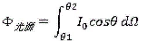
Specifically, the corresponding relation between the emergent angle alpha and the target space luminous flux is calculated according to the light intensity distribution requirement of the anti-collision lamps in GJB 2020A-2012. Referring to fig. 4, the formula used:

wherein IαThe light intensity value is obtained according to the required light intensity distribution fitting and changes along with the angle, and omega is an emergent space solid angle.
It is found after calculation that the angle θ of the light incident on the lens 1 from the LED light source 22 can be divided into two parts: the total reflection theta is belonged to 0 degrees, 46.85 degrees, and the refraction theta is belonged to 46.85 degrees, 90 degrees. The emergent light of total reflection is reflected to alpha epsilon [85 degrees, 90 degrees ], the light fluxes in delta alpha are ensured to be equal, delta alpha is obtained by dividing the angle of the emergent light of total reflection into a plurality of equal parts (namely, one part of equal light fluxes in each angle), and the formula is as follows:

so that Δ ΦLight source=ΔΦReflective lensTherefore, the angle corresponding relation between the incident light and the emergent light of the total reflection lens is obtained.
The total reflection incident surface 16 is a plane, a unit vector of the emergent light of the incident surface is obtained through calculation according to the law of refraction, and the contour coordinates of the total reflection incident surface 16 can be obtained through calculation according to the geometric relation of the incident light as the incident surface is a plane and has a certain height from the light source.
In particular, the total reflection exit surface 12 should have a certain release angle due to the molding process. The exit angle of the light exiting from the total reflection reflecting surface 11 can be calculated by a refraction law formula.
Using the law of refraction: n iso×sinθ=ni×sinα
Wherein n isoIs the refractive index of air, niThe unit vector of the incident light of the total reflection surface can be obtained by taking the refractive index of the lens, theta is the included angle between the incident light of the incident surface of the total reflection lens and the normal, α is the included angle between the emergent light of the incident surface and the normal.
When n isoIs the refractive index of air, niThe unit vector of the emergent light of the total reflection surface can be obtained by taking the refractive index of the lens, theta is the included angle between the emergent light of the total reflection surface and the normal line, and α is the included angle between the incident light of the emergent surface and the normal line.
The unit vector of the emergent light of the total reflection reflecting surface 11 and the unit vector of the emergent light of the total reflection incident surface 16 are combined, and the normal vector of the incident point corresponding to the total reflection reflecting surface 11 can be calculated by using a Snell formula.
There is Snell formula:
wherein n isoIs the spatial refractive index of the emergent ray, niIs the spatial index of refraction of the incident light, is a unit vector of the outgoing light,
 is the unit vector of the incident light ray,
 is the normal vector at the point of incidence.
And calculating the coordinate point of the totally reflected curved surface by using a tangent plane iteration method and the contour dimension of the lens 1.
Using the formula:

wherein The tangent line of the curved surface can be approximately obtained by two adjacent points which are infinitely close. Thus obtaining the set of all surface points.
The starting point of the refraction incidence surface 17 is a coordinate point of the total reflection incidence surface 16 when the light source angle theta is 46.85 degrees, and the contour coordinate of the refraction incidence surface 17 can be calculated according to the determined optical chamber demoulding inclination and the light source incidence angle.
The light flux that needs to be emitted by refraction is: phiRefractive lens=ΦGeneral assembly-ΦTotal reflection lens
For light sources there are formulas

So that Δ ΦLight source=ΔΦRefractive lensThe angle correspondence between the refracted incident ray and the refracted emergent ray is obtained, and the incident ray angle and the unit vector of the refracted emergent surface 14 can be calculated according to the incident ray angle and the refraction law. The unit vector of the incident light and the unit vector of the refracted emergent light of the refraction emergent surface 14 are combined to calculate the normal vector of the corresponding position of the refraction emergent surface 14, and the contour coordinate of the refraction emergent surface 14 can be calculated by using a tangent plane iteration method.
Specifically, the calculation starting point is the angle of 90 ° of the light emitted from the light source corresponding to 90 ° of the refracted emitted light.
Thus, coordinate points of the surface profile of the lens 1 are obtained, and modeling is performed to generate a lens 1 model. In particular, refraction 13 is not calculated due to the influence of the manufacturing process, and as a result, the light intensity value within the emitted light intensity [0 °, 70 ° ] is increased, while the light intensity value within [80 °, 90 ° ] is relatively decreased. The problem can be solved by only increasing the estimated power of the light source by a small amplitude, so that the lens 1 can be ensured to meet the target function, wherein the small amplitude is 2-5% increase of the power of the light source.
The lens 1 in the anti-collision lamp is particularly suitable for SMD (surface mounted device) patch light source array arrangement and COB (chip on board) light sources due to the light distribution effect. It can save artifical equipment, can make the optical effect more perfect through the optimization of secondary grading design moreover to effectively solve the problem that needs powerful and guaranteed 1 light-emitting homogeneity of lens. The secondary light distribution is a means for realizing the illumination requirement after the emergent light of the LED light source is refracted and reflected by the optical system. Here, lens light distribution is meant. To facilitate demolding during manufacture, the refracting entrance face 17 of the lens 1 has a 5 ° draft angle.
According to the existing LED technology, in order to achieve a target light intensity that is high enough, tens of LED light sources for an anti-collision lamp must be used as light emitters, as shown in fig. 3, the LED light source assembly 2 is formed by attaching a plurality of LED light sources 22 to a printed circuit board 21, different light intensity requirements can be achieved by changing the number of the LED light sources 22, and different light color requirements can be achieved by changing the chromaticity of the LED light sources 22. The LED light source 22 may be an aircraft red light source, an aircraft white light source, and may be extended to an infrared light source. The anti-collision lamp provided by the invention has strong adaptability and compatibility, and can realize the light-emitting forms of aviation red, aviation blank and the like only by replacing different LED light sources; and the structure is simpler, the production and assembly cost is reduced, and the flight safety of the airplane is improved.
It can be understood that the anti-collision lamp further comprises a driving power supply 5 positioned in the shell 6, the driving device is in control connection with the LED light source assembly 2, the anti-collision lamp provided by the invention is fixed on the airplane body through the shell 6, and is controlled by the driving power supply 5 to flash, and the driving power supply 5 drives the LED light source 22 to keep flash and strobe operation for 60 times per minute. Compare in the crashproof lamp simple structure that active service aircraft used, need not to add lamp shade protection light source and optical system in addition, improved crashproof lamp's sealing performance and reliability, the maintenance of being more convenient for.
Furthermore, a plurality of cavities are arranged in the housing 6, and the driving power supply 5 and the LED light source assembly 2 are respectively located in different cavities. The driving power supply 5 and the LED light source assembly 2 are provided with two benefits: the first is that the two heat sources are separately arranged to facilitate heat dissipation; and the second is electromagnetic shielding.
In order to facilitate the installation of the lens 1 and to ensure the sealing performance of the product, the bottom ring of the lens 1 is also provided with a flange 15. A press ring 4 is fixedly connected to the housing 6, and the housing 6 fixes the lens 1 by pressing the flange with the press ring 4; the flange with still be provided with sealing washer 3 between the clamping ring 4, sealing washer 3 parcel is on flange 15, and clamping ring 4 and casing 6 pass through screw thread or screw erection joint, through extrusion parcel sealing washer 3 on flange 15 during the installation, produce certain decrement to play sealed effect.
Preferably, the section of the sealing ring 3 along the longitudinal direction of the lens 1 is U-shaped, and the material is silicon rubber.
More preferably, the casing 6 has annular heat dissipation fins uniformly distributed on the periphery thereof near one end of the driving power supply 5. By providing multiple layers of fins on the housing 6, heat from the LED light sources 22 can be dissipated quickly to the air.
In order to improve the light distribution effect, the lens 1 is made of glass, and although the price is higher than that of a plastic material, the effect is better.
The invention is not limited to the examples, and any equivalent changes to the technical solution of the invention by a person skilled in the art after reading the description of the invention are covered by the claims of the invention.
Claims (10)
1. An anti-collision lamp, its characterized in that: the LED lamp comprises a shell, a lens and an LED light source assembly, wherein the lens is embedded in the top of the shell, and the LED light source assembly is positioned in the shell and arranged below the lens; the lens is a rotating body, a conical groove is formed on the upper end surface of the lens, a flat groove is formed on the lower end surface of the lens, and the peripheral surface of the lens is transited from an inclined surface to a spherical surface from top to bottom to form a total reflection area and a refraction area; the angle range of the light emitted by the LED light source component totally reflected by the total reflection region is theta epsilon [0 degrees ] and 46.85 degrees ], and the angle range of the light refracted by the refraction region is theta epsilon [46.85 degrees ] and 90 degrees ].
2. The anti-collision lamp according to claim 1, characterized in that: the lens comprises a refraction incidence surface, a total reflection surface, a total reflection emergent surface, a transition surface and a refraction emergent surface from the upper end surface to the lower end surface;
the refraction incidence surface is a rotating surface with demoulding inclination, the total reflection incidence surface is a plane vertical to the light emitting direction of the LED light source component, and the refraction incidence surface and the total reflection incidence surface are connected to form the flat groove; the total reflection reflecting surface is a rotating body with a curved bus and a downward vertex so as to form the conical groove; the total reflection emergent surface, the transition surface and the refraction emergent surface are positioned on the peripheral surface, the total reflection emergent surface is a cylindrical surface with a demoulding inclination, and the concave transition surface and the convex refraction emergent surface are sequentially arranged below the total reflection emergent surface.
3. The anti-collision light of claim 2, wherein: the demolding inclination of the refraction incidence surface is 5 degrees.
4. The anti-collision lamp according to claim 1 or 2, characterized in that: the LED light source assembly comprises a printed circuit board and a plurality of LED light sources, and the LED light sources are arranged on the printed circuit board in an array form; the LED light sources are red light sources or white light sources.
5. The anti-collision light of claim 4, wherein: the LED lamp is characterized by further comprising a driving power supply located in the shell, and the driving device is connected with the LED light source assembly in a control mode to control the LED light sources to flicker.
6. The anti-collision light of claim 5, wherein: the shell is internally provided with a plurality of cavities, and the driving power supply and the LED light source assembly are respectively positioned in different cavities.
7. The anti-collision light of claim 6, wherein: a flange is further arranged at one circle of the bottom of the lens, a pressing ring is further fixedly connected to the shell, and the shell fixes the lens by pressing the flange with the pressing ring; and a sealing ring is also arranged between the flange and the pressing ring.
8. The anti-collision light of claim 7, wherein: the section of the sealing ring along the longitudinal direction of the lens is U-shaped, and the sealing ring is made of silicon rubber; the lens is made of glass.
9. The anti-collision light of claim 8, wherein: annular heat radiating fins are uniformly distributed on the periphery of one end, close to the driving power supply, of the shell.
10. An anti-collision light as claimed in claim 1 or 2, characterised in that the surface profile of the lens is determined as:
dividing the angle theta of light rays incident to the lens into two parts, wherein the total reflection theta belongs to [0 DEG, 46.85 DEG ], and the refraction theta belongs to [46.85 DEG, 90 DEG ];
reflecting the totally reflected emergent light to alpha epsilon to [85 degrees, 90 degrees ], planning the emergent total reflection angle alpha to be a plurality of parts, and enabling the luminous fluxes in delta alpha to be equal to each other based on

Let Δ ΦLight source=ΔΦReflective lensObtaining the angle corresponding relation between the incident light and the emergent light of the total reflection lens;
calculating to obtain the contour coordinate of the total reflection incident surface according to the unit vector of the emergent light of the incident surface and the geometric relation of the incident light;
using the law of refraction: n iso×sinθ=ni×sinα
Wherein n isoIs the refractive index of air, niIs the refractive index of the lens, theta is the included angle between the incident light and the normal of the incident surface of the total reflection lens, α is the included angle between the emergent light and the normal of the incident surface, and the unit direction of the incident light of the total reflection surface is obtainedAn amount;
when n isoIs the refractive index of air, niThe refractive index of the lens is theta, the included angle between the emergent light ray of the total reflection lens and the normal is theta, α is the included angle between the incident light ray of the emergent surface and the normal, and the unit vector of the emergent light ray of the total reflection surface is obtained;
combining the unit vector of the emergent ray of the total reflection reflecting surface and the unit vector of the emergent ray of the total reflection incident surface, and obtaining a normal vector of the total reflection reflecting surface corresponding to an incident point through a Snell formula:
wherein the content of the first and second substances, is a unit vector of the outgoing light,
 is the unit vector of the incident light ray,
 is the normal vector at the point of incidence;
calculating the coordinate point of the totally reflected curved surface by using a tangent plane iteration method and the outline size of the lens: wherein the content of the first and second substances,
 the surface is a curved surface tangent line, and two adjacent points which are infinitely close can be approximately solved to obtain a set of all surface points of total reflection;
the starting point of the refraction incidence surface is a coordinate point of the total reflection incidence surface when the light source angle theta is 46.85 degrees, and the contour coordinate of the refraction incidence surface is obtained according to the determined demoulding inclination of the light chamber and the light source incidence angle;
the light flux that needs to be emitted by refraction is: phiRefractive lens=ΦGeneral assembly-ΦTotal reflection lens
There are formulas for light sources;
so that Δ ΦLight source=ΔΦRefractive lensObtaining the angle corresponding relation between the refraction incident light and the refraction emergent light, calculating the incident light angle and the unit vector of the refraction emergent surface according to the incident light angle and the refraction law, calculating the normal vector of the corresponding position of the refraction emergent surface by combining the incident light unit vector and the refraction emergent light unit vector of the refraction emergent surface, and obtaining the contour coordinate of the refraction emergent surface by utilizing tangent plane iteration;
and taking the light ray corresponding to the refracted emergent ray of 90 degrees when the emergent ray angle of the light source is 90 degrees as a calculation starting point to obtain a coordinate point of the surface contour of the lens.
Priority Applications (1)
| Application Number | Priority Date | Filing Date | Title |
|---|---|---|---|
| CN202010328534.2A CN111578233A (en) | 2020-04-23 | 2020-04-23 | Anti-collision lamp |
Applications Claiming Priority (1)
| Application Number | Priority Date | Filing Date | Title |
|---|---|---|---|
| CN202010328534.2A CN111578233A (en) | 2020-04-23 | 2020-04-23 | Anti-collision lamp |
Publications (1)
| Publication Number | Publication Date |
|---|---|
| CN111578233A true CN111578233A (en) | 2020-08-25 |
Family
ID=72114964
Family Applications (1)
| Application Number | Title | Priority Date | Filing Date |
|---|---|---|---|
| CN202010328534.2A Pending CN111578233A (en) | 2020-04-23 | 2020-04-23 | Anti-collision lamp |
Country Status (1)
| Country | Link |
|---|---|
| CN (1) | CN111578233A (en) |
Cited By (1)
| Publication number | Priority date | Publication date | Assignee | Title |
|---|---|---|---|---|
| CN112128653A (en) * | 2020-09-22 | 2020-12-25 | 兰州万里航空机电有限责任公司 | A miniaturized red light anticollision lamp for big aircraft |
Citations (9)
| Publication number | Priority date | Publication date | Assignee | Title |
|---|---|---|---|---|
| CN201795384U (en) * | 2010-08-17 | 2011-04-13 | 南京汉德森科技股份有限公司 | Pressure buckled LED spot lamp |
| CN102062349A (en) * | 2010-09-07 | 2011-05-18 | 上海三思电子工程有限公司 | Side-light panoramic lens for LED |
| CN102072458A (en) * | 2010-11-20 | 2011-05-25 | 特殊光电科技(中山)有限公司 | Lens for LED lamp |
| CN104344347A (en) * | 2014-10-14 | 2015-02-11 | 程灏波 | Free curved lens based on single-LED vertical taxiway edge lamp |
| CN104566217A (en) * | 2015-01-21 | 2015-04-29 | 华南理工大学 | Two-free-curved-surface optical lens used for ultrathin direct-lit type LED backlight system |
| CN104676473A (en) * | 2013-11-29 | 2015-06-03 | 海洋王(东莞)照明科技有限公司 | Lens and lamp using same |
| KR20170077578A (en) * | 2015-12-28 | 2017-07-06 | 인하대학교 산학협력단 | Total Internal Reflection LED Lens and Design Method Thereof |
| CN111023042A (en) * | 2019-12-20 | 2020-04-17 | 东南大学 | LED collimation optical lens |
| CN212157033U (en) * | 2020-04-23 | 2020-12-15 | 陕西锐士电子技术有限公司 | Anti-collision lamp |
-
2020
- 2020-04-23 CN CN202010328534.2A patent/CN111578233A/en active Pending
Patent Citations (9)
| Publication number | Priority date | Publication date | Assignee | Title |
|---|---|---|---|---|
| CN201795384U (en) * | 2010-08-17 | 2011-04-13 | 南京汉德森科技股份有限公司 | Pressure buckled LED spot lamp |
| CN102062349A (en) * | 2010-09-07 | 2011-05-18 | 上海三思电子工程有限公司 | Side-light panoramic lens for LED |
| CN102072458A (en) * | 2010-11-20 | 2011-05-25 | 特殊光电科技(中山)有限公司 | Lens for LED lamp |
| CN104676473A (en) * | 2013-11-29 | 2015-06-03 | 海洋王(东莞)照明科技有限公司 | Lens and lamp using same |
| CN104344347A (en) * | 2014-10-14 | 2015-02-11 | 程灏波 | Free curved lens based on single-LED vertical taxiway edge lamp |
| CN104566217A (en) * | 2015-01-21 | 2015-04-29 | 华南理工大学 | Two-free-curved-surface optical lens used for ultrathin direct-lit type LED backlight system |
| KR20170077578A (en) * | 2015-12-28 | 2017-07-06 | 인하대학교 산학협력단 | Total Internal Reflection LED Lens and Design Method Thereof |
| CN111023042A (en) * | 2019-12-20 | 2020-04-17 | 东南大学 | LED collimation optical lens |
| CN212157033U (en) * | 2020-04-23 | 2020-12-15 | 陕西锐士电子技术有限公司 | Anti-collision lamp |
Cited By (1)
| Publication number | Priority date | Publication date | Assignee | Title |
|---|---|---|---|---|
| CN112128653A (en) * | 2020-09-22 | 2020-12-25 | 兰州万里航空机电有限责任公司 | A miniaturized red light anticollision lamp for big aircraft |
Similar Documents
| Publication | Publication Date | Title |
|---|---|---|
| US10174908B2 (en) | LED device for wide beam generation | |
| US8147100B2 (en) | Lighting device | |
| US9388949B2 (en) | LED device for wide beam generation | |
| TWI512237B (en) | Lighting system | |
| US20110228534A1 (en) | highly-efficient and high-power led light source, an led lamp which uses the light source and the application of the lamp | |
| TWI662224B (en) | Vehicle led linear lighting module | |
| CN111023042B (en) | LED collimation optical lens | |
| CN104603521B (en) | Lighting device | |
| CN103511977A (en) | Lens and omni-directional lighting device and modified lamp provided with lens | |
| CN212157033U (en) | Anti-collision lamp | |
| CA2787769C (en) | An improved led device for wide beam generation | |
| CN111578233A (en) | Anti-collision lamp | |
| CN103017084B (en) | Secondary optical lens for light emitting diode (LED) wide-angle bulb lamp and LED wide-angle bulb lamp | |
| CN210271585U (en) | LED display screen capable of eliminating moire and improving light mixing effect | |
| CN210601304U (en) | Reflective LED lamp based on diffuse reflection nano spinning | |
| CN207865058U (en) | Array-type LED lighting device | |
| CN208349202U (en) | Automobile LED distance-light Integral mold group | |
| CN113339749A (en) | Small-caliber high beam unit and assembly thereof | |
| CN207999786U (en) | A kind of leaded light hollow lens and LED lamp bead | |
| CN206892528U (en) | A kind of light compensating lamp for road monitoring | |
| CN111350999A (en) | Landing and sliding lamp | |
| CN207555222U (en) | A kind of LED light component | |
| CN205001886U (en) | Luminous LED lamp of no dark space wide -angle | |
| CN104251391A (en) | LED (light-emitting diode) bulb lamp | |
| CN216131894U (en) | Reflective light distribution structure for airport navigation lighting and airport navigation lighting lamp |
Legal Events
| Date | Code | Title | Description |
|---|---|---|---|
| PB01 | Publication | ||
| PB01 | Publication | ||
| SE01 | Entry into force of request for substantive examination | ||
| SE01 | Entry into force of request for substantive examination |