CN111578207A - Modern garden landscape exploration equipment at night - Google Patents
Modern garden landscape exploration equipment at night Download PDFInfo
- Publication number
- CN111578207A CN111578207A CN202010475783.4A CN202010475783A CN111578207A CN 111578207 A CN111578207 A CN 111578207A CN 202010475783 A CN202010475783 A CN 202010475783A CN 111578207 A CN111578207 A CN 111578207A
- Authority
- CN
- China
- Prior art keywords
- shell
- fixed
- driving
- housing
- circuit board
- Prior art date
- Legal status (The legal status is an assumption and is not a legal conclusion. Google has not performed a legal analysis and makes no representation as to the accuracy of the status listed.)
- Granted
Links
Images

Classifications
-
- F—MECHANICAL ENGINEERING; LIGHTING; HEATING; WEAPONS; BLASTING
- F21—LIGHTING
- F21S—NON-PORTABLE LIGHTING DEVICES; SYSTEMS THEREOF; VEHICLE LIGHTING DEVICES SPECIALLY ADAPTED FOR VEHICLE EXTERIORS
- F21S9/00—Lighting devices with a built-in power supply; Systems employing lighting devices with a built-in power supply
- F21S9/02—Lighting devices with a built-in power supply; Systems employing lighting devices with a built-in power supply the power supply being a battery or accumulator
- F21S9/028—Lighting devices with a built-in power supply; Systems employing lighting devices with a built-in power supply the power supply being a battery or accumulator rechargeable by using hydropower, e.g. using water powered turbines
-
- F—MECHANICAL ENGINEERING; LIGHTING; HEATING; WEAPONS; BLASTING
- F21—LIGHTING
- F21S—NON-PORTABLE LIGHTING DEVICES; SYSTEMS THEREOF; VEHICLE LIGHTING DEVICES SPECIALLY ADAPTED FOR VEHICLE EXTERIORS
- F21S9/00—Lighting devices with a built-in power supply; Systems employing lighting devices with a built-in power supply
- F21S9/02—Lighting devices with a built-in power supply; Systems employing lighting devices with a built-in power supply the power supply being a battery or accumulator
- F21S9/03—Lighting devices with a built-in power supply; Systems employing lighting devices with a built-in power supply the power supply being a battery or accumulator rechargeable by exposure to light
- F21S9/037—Lighting devices with a built-in power supply; Systems employing lighting devices with a built-in power supply the power supply being a battery or accumulator rechargeable by exposure to light the solar unit and the lighting unit being located within or on the same housing
-
- F—MECHANICAL ENGINEERING; LIGHTING; HEATING; WEAPONS; BLASTING
- F21—LIGHTING
- F21S—NON-PORTABLE LIGHTING DEVICES; SYSTEMS THEREOF; VEHICLE LIGHTING DEVICES SPECIALLY ADAPTED FOR VEHICLE EXTERIORS
- F21S9/00—Lighting devices with a built-in power supply; Systems employing lighting devices with a built-in power supply
- F21S9/04—Lighting devices with a built-in power supply; Systems employing lighting devices with a built-in power supply the power supply being a generator
- F21S9/046—Lighting devices with a built-in power supply; Systems employing lighting devices with a built-in power supply the power supply being a generator driven by hydropower, e.g. by water powered turbines
-
- F—MECHANICAL ENGINEERING; LIGHTING; HEATING; WEAPONS; BLASTING
- F21—LIGHTING
- F21V—FUNCTIONAL FEATURES OR DETAILS OF LIGHTING DEVICES OR SYSTEMS THEREOF; STRUCTURAL COMBINATIONS OF LIGHTING DEVICES WITH OTHER ARTICLES, NOT OTHERWISE PROVIDED FOR
- F21V15/00—Protecting lighting devices from damage
- F21V15/01—Housings, e.g. material or assembling of housing parts
-
- F—MECHANICAL ENGINEERING; LIGHTING; HEATING; WEAPONS; BLASTING
- F21—LIGHTING
- F21V—FUNCTIONAL FEATURES OR DETAILS OF LIGHTING DEVICES OR SYSTEMS THEREOF; STRUCTURAL COMBINATIONS OF LIGHTING DEVICES WITH OTHER ARTICLES, NOT OTHERWISE PROVIDED FOR
- F21V15/00—Protecting lighting devices from damage
- F21V15/02—Cages
-
- F—MECHANICAL ENGINEERING; LIGHTING; HEATING; WEAPONS; BLASTING
- F21—LIGHTING
- F21V—FUNCTIONAL FEATURES OR DETAILS OF LIGHTING DEVICES OR SYSTEMS THEREOF; STRUCTURAL COMBINATIONS OF LIGHTING DEVICES WITH OTHER ARTICLES, NOT OTHERWISE PROVIDED FOR
- F21V19/00—Fastening of light sources or lamp holders
-
- F—MECHANICAL ENGINEERING; LIGHTING; HEATING; WEAPONS; BLASTING
- F21—LIGHTING
- F21V—FUNCTIONAL FEATURES OR DETAILS OF LIGHTING DEVICES OR SYSTEMS THEREOF; STRUCTURAL COMBINATIONS OF LIGHTING DEVICES WITH OTHER ARTICLES, NOT OTHERWISE PROVIDED FOR
- F21V23/00—Arrangement of electric circuit elements in or on lighting devices
- F21V23/02—Arrangement of electric circuit elements in or on lighting devices the elements being transformers, impedances or power supply units, e.g. a transformer with a rectifier
- F21V23/023—Power supplies in a casing
-
- F—MECHANICAL ENGINEERING; LIGHTING; HEATING; WEAPONS; BLASTING
- F21—LIGHTING
- F21V—FUNCTIONAL FEATURES OR DETAILS OF LIGHTING DEVICES OR SYSTEMS THEREOF; STRUCTURAL COMBINATIONS OF LIGHTING DEVICES WITH OTHER ARTICLES, NOT OTHERWISE PROVIDED FOR
- F21V23/00—Arrangement of electric circuit elements in or on lighting devices
- F21V23/04—Arrangement of electric circuit elements in or on lighting devices the elements being switches
- F21V23/0442—Arrangement of electric circuit elements in or on lighting devices the elements being switches activated by means of a sensor, e.g. motion or photodetectors
- F21V23/0464—Arrangement of electric circuit elements in or on lighting devices the elements being switches activated by means of a sensor, e.g. motion or photodetectors the sensor sensing the level of ambient illumination, e.g. dawn or dusk sensors
-
- F—MECHANICAL ENGINEERING; LIGHTING; HEATING; WEAPONS; BLASTING
- F21—LIGHTING
- F21V—FUNCTIONAL FEATURES OR DETAILS OF LIGHTING DEVICES OR SYSTEMS THEREOF; STRUCTURAL COMBINATIONS OF LIGHTING DEVICES WITH OTHER ARTICLES, NOT OTHERWISE PROVIDED FOR
- F21V29/00—Protecting lighting devices from thermal damage; Cooling or heating arrangements specially adapted for lighting devices or systems
- F21V29/50—Cooling arrangements
- F21V29/70—Cooling arrangements characterised by passive heat-dissipating elements, e.g. heat-sinks
- F21V29/74—Cooling arrangements characterised by passive heat-dissipating elements, e.g. heat-sinks with fins or blades
-
- F—MECHANICAL ENGINEERING; LIGHTING; HEATING; WEAPONS; BLASTING
- F21—LIGHTING
- F21V—FUNCTIONAL FEATURES OR DETAILS OF LIGHTING DEVICES OR SYSTEMS THEREOF; STRUCTURAL COMBINATIONS OF LIGHTING DEVICES WITH OTHER ARTICLES, NOT OTHERWISE PROVIDED FOR
- F21V3/00—Globes; Bowls; Cover glasses
-
- F—MECHANICAL ENGINEERING; LIGHTING; HEATING; WEAPONS; BLASTING
- F21—LIGHTING
- F21W—INDEXING SCHEME ASSOCIATED WITH SUBCLASSES F21K, F21L, F21S and F21V, RELATING TO USES OR APPLICATIONS OF LIGHTING DEVICES OR SYSTEMS
- F21W2131/00—Use or application of lighting devices or systems not provided for in codes F21W2102/00-F21W2121/00
- F21W2131/10—Outdoor lighting
- F21W2131/109—Outdoor lighting of gardens
-
- Y—GENERAL TAGGING OF NEW TECHNOLOGICAL DEVELOPMENTS; GENERAL TAGGING OF CROSS-SECTIONAL TECHNOLOGIES SPANNING OVER SEVERAL SECTIONS OF THE IPC; TECHNICAL SUBJECTS COVERED BY FORMER USPC CROSS-REFERENCE ART COLLECTIONS [XRACs] AND DIGESTS
- Y02—TECHNOLOGIES OR APPLICATIONS FOR MITIGATION OR ADAPTATION AGAINST CLIMATE CHANGE
- Y02B—CLIMATE CHANGE MITIGATION TECHNOLOGIES RELATED TO BUILDINGS, e.g. HOUSING, HOUSE APPLIANCES OR RELATED END-USER APPLICATIONS
- Y02B20/00—Energy efficient lighting technologies, e.g. halogen lamps or gas discharge lamps
- Y02B20/72—Energy efficient lighting technologies, e.g. halogen lamps or gas discharge lamps in street lighting
Abstract
The invention discloses a modern garden landscape night exploration device, which is provided with a rotary protection component, so that when the device does not work, a lampshade is covered by the rotary protection component, so that the lampshade is separated from the outside, the lampshade is prevented from being damaged due to external damage and impact and the like, dust and mud on the lampshade are prevented from falling, further the lighting effect is reduced, even the lighting capability is lost, a water collecting tank and a power generation device are arranged, the device can drive a generator to rotate through water flow in rainy and snowy weather, further electric energy is generated and stored, a photovoltaic panel is arranged, the device can generate and store the electric energy through sunlight in sunny weather, so that the energy consumption is greatly reduced, the energy is saved, and a heat conduction fixing column, a heat conduction screw and a heat dissipation fin are arranged, so that the device can be effectively dissipated heat, further the device is prevented from being damaged due to overhigh temperature inside the device, greatly prolonging the service life of the equipment.
Description
Technical Field
The invention belongs to the technical field of modern garden landscape searchlighting equipment; in particular to a modern garden landscape night exploration device.
Background
Modern gardens are combined products of plants and modern buildings, and the rapid development of urban modern construction leads to the gradual deterioration of the ecological environment. People desire the desire of protecting the environment, improving the environment, being close and returning to nature, and promoting the rapid development of garden careers, the garden landscape is divided into night view and day view, the night view of modern garden landscape and searchlighting equipment supplement each other, the existing searchlighting equipment is directly buried under the ground, the surface is not provided with a protection component, so that when the searchlighting equipment is not needed, the lampshade of the existing searchlighting equipment is always in contact with the outside, the lampshade is easy to be damaged by damage and impact of the outside, meanwhile, the lampshade is easy to fall on dust and soil, the lighting effect is reduced and even the lighting capability is lost, the existing searchlighting equipment completely adopts an external power supply to supply power, thereby the loss of a large amount of electric energy is caused, the energy is not effectively saved, the existing searchlighting equipment is directly buried on the ground, no heat dissipation component is arranged, the heat of the searchlighting equipment can not be effectively dissipated, and the equipment, the service life of the device is greatly reduced, so that the modern garden landscape night exploration device which has a protective result on a lampshade, can generate electricity by itself and has good heat dissipation performance is urgent.
Disclosure of Invention
The invention aims to provide modern garden landscape night exploration equipment which comprises a rotary protection component, a water collecting tank, a sealing shell, a protection component driving device, an electric power storage device, a power generation device, a lamp holder and a light collecting cover, wherein the rotary protection component is fixed on the upper end surface of the sealing shell, the water collecting tank is sleeved on the upper side of the outer side wall of the sealing shell and is fixedly connected with the outer side wall of the sealing shell and the outer side wall of the rotary protection component, the inside of the water collecting tank is communicated with the lower half part of the inner side of the sealing shell, the light collecting cover is embedded in the sealing shell and is positioned on the lower end surface of the rotary protection component, the lamp holder is fixedly embedded in the inner side wall of the sealing shell, the upper end surface of the lamp holder is fixedly connected with the lower end surface of the light collecting cover, the upper end of, and protection component drive arrangement and rotatory protection component fixed connection, protection component drive arrangement upper end and power storage device lower extreme fixed connection, and protection component drive arrangement and power storage device electric connection, power storage device is embedded to be fixed in on the sealed casing inside wall, the power storage device upper end is fixed with power generation facility, power generation facility is embedded in on the inside wall of the inboard latter half of sealed casing.
Further, rotatory protection subassembly includes rotating vane group, blade upper cover, blade base, belt pulley and drive pivot, rotating vane group comprises a plurality of blades, and is a plurality of the blade is fixed in between blade upper cover and the blade base through a plurality of drive pivot rotations, the blade upper cover is located blade base upside, and is a plurality of the blade passes through a plurality of drive pivots and converts between circular seal structure and open structure, and is a plurality of drive pivot lower extreme all pierces through the seal housing up end and stretches in the seal housing downside, and is a plurality of drive pivot lower extreme all is fixed with the belt pulley, be equipped with photovoltaic board and photosensor on the blade upper cover up end, photovoltaic board and photosensor all with circuit board electric connection.
Further, the water catch bowl includes filter screen and clamshell, the clamshell has end hollow shell for there being not the top, the clamshell overlaps on sealed casing lateral wall, and clamshell and sealed casing fixed connection, the filter screen is the ring type, the filter screen is fixed in on the clamshell up end, and is located between clamshell up end edge and the blade upper cover lateral wall.
Further, sealed casing includes drive pivot dead eye, the logical groove of intaking, joint support frame, sealed shell and sealed shell inner shell all are no top hollow cylinder at the end, sealed shell inner shell overlaps inside sealed shell, and sealed shell inner shell upper end edge and sealed shell upper end edge fixed connection, sealed shell outer shell lateral wall leads to groove through connection through intaking with sealed shell inner shell inside wall, joint support frame is fixed in on the sealed shell inner shell inside wall, and is located sealed shell inner shell inside wall downside, drive pivot dead eye is located between sealed shell inner shell upper end edge and the sealed shell outer shell upper end edge, drive pivot dead eye internal rotation is fixed with the drive pivot.
Further, the protection component driving device comprises a driving shell bottom cover, a driving belt pulley, a driving motor, a driving belt, a driven belt pulley, a driven belt, a driving shell and a sealing bottom cover, the driving shell is fixed on the lower end surface of the connecting support frame, the driving motor is fixed on the inner side of the driving shell, a driving belt pulley is fixed on an output shaft of the driving motor, a bottom cover of the driving shell is fixed on the driving shell, the driven belt is used for driving and connecting belt pulleys at the lower ends of the plurality of driving rotating shafts, the driven belt pulley is fixed at the tail end of any one of the plurality of driving rotating shafts, the driven belt pulley is arranged between the outer shell of the sealing shell and the inner shell of the sealing shell, the sealing bottom cover is fixed between the lower end faces of the outer shell of the sealing shell and the inner shell of the sealing shell, and the driven belt pulley is in transmission connection with the driving belt pulley through a driving belt.
Further, power storage device includes battery and circuit board, the battery is installed on the circuit board, and battery and circuit board electric connection, the circuit board is fixed in on the drive shell inside wall, be fixed with driving motor on the circuit board, driving motor and circuit board electric connection, the battery is the ring type.
Further, the power generation device comprises a micro generator, a generator fixing frame, a generator rotor and water wheel blades, the micro generator is fixed on the driving shell through the generator fixing frame, the micro generator is electrically connected with the circuit board, and the water wheel blades are uniformly fixed on the generator rotor.
The lamp holder comprises a lamp holder, a lamp shell, a heat conduction fixing column, a heat conduction screw, a lamp holder circuit board, a lamp shell rear cover, heat dissipation fins and a lamp holder mounting seat, the lamp holder is fixedly mounted on the lamp holder mounting seat, the lamp holder mounting seat is fixed on the lamp holder circuit board, the lamp holder is electrically connected with the lamp holder circuit board, the lamp holder circuit board is fixed on the inner side of the lamp shell through the heat conduction fixing column, the heat dissipation fins are fixed on the lower end face of the lamp shell rear cover, the lamp shell rear cover is fixed on the lower end face of the lamp shell through the heat conduction screw, and the heat conduction.
Furthermore, the light collecting cover comprises a glass sheet, a light condensing groove and a light collecting cover body, the light collecting cover body is a cylinder, the light condensing groove is formed in the upper end face of the light collecting cover body, the light condensing groove penetrates through the upper end face and the lower end face of the light collecting cover body, the light condensing groove is in an inverted truncated cone shape, the glass sheet is fixed on the upper end face of the light collecting cover body, and the lamp cap is arranged on the inner side of the light condensing groove.
Further, the working principle of the modern landscape exploration equipment at night is as follows:
1) the invention is buried on the land under the garden landscape;
2) in daytime, when a photosensitive sensor on the rotary protection component (1) receives a strong light signal, a highlight signal is generated and transmitted to the circuit board (52), and the circuit board (52) supplies power to the driving motor (43) to enable the driving motor (43) to rotate reversely;
3) the driving motor (43) rotates reversely to drive the belt pulley (14) to rotate reversely, and further drive the driving rotating shaft (15) to rotate reversely, so that the rotating blade group (11) is closed, and the lampshade is separated from the outside;
4) when the light sensor on the rotary protection component (1) receives a no light or low brightness signal at night, a low light signal is generated and transmitted to the circuit board (52), and the circuit board (52) supplies power to the driving motor (43) to enable the driving motor (43) to rotate forwards;
5) the driving motor (43) rotates forwards to drive the belt pulley (14) to rotate forwards, so that the driving rotating shaft (15) is driven to rotate forwards, the rotating blade group (11) is unfolded, the lampshade is exposed to the outside, meanwhile, the lamp head circuit board (75) supplies power to the lamp head (71), and the lamp head (71) illuminates the landscape, so that personnel can explore the garden landscape at night conveniently;
6) in sunny days, the photovoltaic panel on the rotary protection assembly (1) collects light energy, converts the light energy into electric energy and stores the electric energy in the storage battery (51);
7) in rainy days, rainwater can enter the shell cover (22) through the filter screen (21), enters the lower half part of the inner side of the sealing shell (3) through the shell cover (22), then drives the water wheel blade (64) to rotate, and the water wheel blade (64) drives the generator rotor (63) to rotate, so that the micro generator (61) generates electric energy, and the electric energy is stored in the storage battery (51).
The invention has the beneficial effects that: the rotary protection component is arranged, so that when the rotary protection component is not used, the lampshade is separated from the outside, the lampshade is prevented from being damaged due to external damage and impact, dust and mud fall on the lampshade, the lighting effect is further reduced, even the lighting capacity is lost, the device can be driven by water flow to rotate through the water collection tank and the power generation device in rainy and snowy weather, electric energy is further generated and stored, the device can be used for generating and storing electric energy through sunlight in sunny weather through the photovoltaic panel, the energy consumption is greatly reduced, energy is saved, the heat conduction fixing column, the heat conduction screw and the heat dissipation fins are arranged to effectively dissipate heat of the device, the device is prevented from being damaged due to overhigh temperature in the device, and the service life of the device is greatly prolonged.
Drawings
In order to facilitate understanding for those skilled in the art, the present invention will be further described with reference to the accompanying drawings.
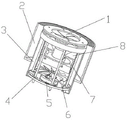
FIG. 1 is a schematic diagram of the general structure of a modern landscape exploration device at night;
FIG. 2 is a schematic diagram of the structure of a rotary protection assembly of the night exploration equipment for the modern garden landscape;
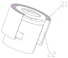
FIG. 3 is a schematic structural diagram of a water collecting tank of the night exploration equipment for the modern garden landscape of the invention;
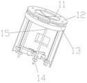
FIG. 4 is a schematic structural diagram of a sealing shell of the night exploration equipment for the modern garden landscape;
FIG. 5 is a schematic structural diagram of a driving device of a protection component of the modern garden landscape night exploration equipment;
FIG. 6 is a schematic structural diagram of an electricity storage device of the modern garden landscape night exploration equipment;
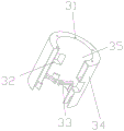
FIG. 7 is a schematic structural diagram of a power generation device of the modern garden landscape night exploration equipment;
FIG. 8 is a schematic structural diagram of a lamp holder of the night exploration equipment for the modern garden landscape of the invention;
fig. 9 is a schematic structural diagram of a light collecting cover of the modern garden landscape night exploration device.
Detailed Description
Referring to fig. 1-9, a modern garden landscape night exploration device comprises a rotary protection component 1, a water collection tank 2, a seal housing 3, a protection component driving device 4, an electric storage device 5, a power generation device 6, a lamp holder 7 and a light collection cover 8, wherein the rotary protection component 1 is fixed on the upper end surface of the seal housing 3, the water collection tank 2 is sleeved on the upper side of the outer side wall of the seal housing 3, the water collection tank 2 is fixedly connected with the outer side wall of the seal housing 3 and the outer side wall of the rotary protection component 1, the inner part of the water collection tank 2 is communicated with the lower half part of the inner side of the seal housing 3, the light collection cover 8 is embedded in the seal housing 3, the light collection cover 8 is positioned on the lower end surface of the rotary protection component 1, the lamp holder 7 is fixedly embedded in the inner side wall of the seal housing 3, the upper end surface of, protection component drive arrangement 4 locates sealed housing 3 bottom, and protection component drive arrangement 4 and 1 fixed connection of rotatory protection component, protection component drive arrangement 4 upper end and 5 lower extreme fixed connection of power storage device, and protection component drive arrangement 4 and 5 electric connection of power storage device, power storage device 5 is embedded to be fixed in on the 3 inside walls of sealed housing, power storage device 5 upper end is fixed with power generation facility 6, power generation facility 6 is embedded on the inside wall of 3 inboard the latter half of sealed housing.
As shown in fig. 2, the rotation protection assembly 1 includes a rotating blade set 11, a blade upper cover 12, a blade base 13, a belt pulley 14 and a driving rotating shaft 15, the rotating blade set 11 is composed of a plurality of blades, the plurality of blades are rotationally fixed between the blade upper cover 12 and the blade base 13 through the plurality of driving rotating shafts 15, the blade upper cover 12 is located on the upper side of the blade base 13, the plurality of blades are switched between a circular sealing structure and an opening structure through the plurality of driving rotating shafts 15, the lower ends of the plurality of driving rotating shafts 15 all penetrate through the upper end surface of the sealing shell 3 and extend to the lower side of the sealing shell 3, the belt pulley 14 is fixed at the lower ends of the plurality of driving rotating shafts 15, a photovoltaic panel and a photosensitive sensor are arranged on the upper end surface of the blade upper cover 12.
As shown in fig. 3, the water collection tank 2 includes a filter screen 21 and a housing 22, the housing 22 is a hollow housing without a top and a bottom, the housing 22 is sleeved on the outer side wall of the sealing housing 3, the housing 22 is fixedly connected with the sealing housing 3, the filter screen 21 is circular, the filter screen 21 is fixed on the upper end surface of the housing 22 and is located between the edge of the upper end surface of the housing 22 and the outer side wall of the upper cover 12 of the blade.
As shown in fig. 4, the sealing shell 3 includes a driving shaft bearing hole 31, a water inlet through groove 32, a connection support frame 33, a sealing shell outer shell 34 and a sealing shell inner shell 35, the sealing shell outer shell 34 and the sealing shell inner shell 35 are all hollow cylinders without top and bottom, the sealing shell inner shell 35 is sleeved inside the sealing shell outer shell 34, the upper end edge of the sealing shell inner shell 35 is fixedly connected with the upper end edge of the sealing shell outer shell 34, the outer side wall of the sealing shell outer shell 34 and the inner side wall of the sealing shell inner shell 35 are connected through the water inlet through groove 32, the connection support frame 33 is fixed on the inner side wall of the sealing shell inner shell 35 and is located on the lower side of the inner side wall of the sealing shell 35, the driving shaft bearing hole 31 is arranged between the upper end edge of the sealing shell inner shell 35 and the upper end edge.
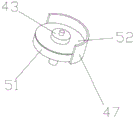
As shown in fig. 5, the protection member driving means 4 includes a driving housing bottom cover 41, a driving pulley 42, a driving motor 43, a driving belt 44, the sealing device comprises a driven pulley 45, a driven belt 46, a driving shell 47 and a sealing bottom cover 48, wherein the driving shell 47 is fixed on the lower end face of the connecting support frame 33, the driving motor 43 is fixed on the inner side of the driving shell 47, the driving pulley 42 is fixed on an output shaft of the driving motor 43, the driving shell bottom cover 41 is fixed on the driving shell 47, the driven belt 46 is used for driving and connecting the pulleys 14 at the lower ends of a plurality of driving rotating shafts 15, the driven pulley 45 is fixed at the tail end of any one driving rotating shaft 15 in the plurality of driving rotating shafts 15, the driven pulley 45 is arranged between the sealing shell outer shell 34 and the sealing shell inner shell 35, the sealing bottom cover 48 is fixed between the sealing shell outer shell 34 and the lower end face of the sealing.
As shown in fig. 6, the power storage device 5 includes a battery 51 and a circuit board 52, the battery 51 is mounted on the circuit board 52, the battery 51 is electrically connected to the circuit board 52, the circuit board 52 is fixed on the inner sidewall of the driving housing 47, the driving motor 43 is fixed on the circuit board 52, the driving motor 43 is electrically connected to the circuit board 52, and the battery 51 is circular.
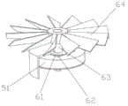
As shown in fig. 7, the power generation device 6 includes a micro-generator 61, a generator fixing frame 62, a generator rotor 63 and water turbine blades 64, the micro-generator 61 is fixed on the driving housing 47 through the generator fixing frame 62, the micro-generator 61 is electrically connected to the circuit board 52, and the water turbine blades 64 are uniformly fixed on the generator rotor 63.
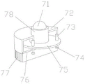
As shown in fig. 8, the lamp socket 7 includes a lamp cap 71, a lamp housing 72, a heat conducting fixing post 73, a heat conducting screw 74, a lamp cap circuit board 75, a lamp housing rear cover 76, a heat dissipating fin 77, and a lamp cap mounting base 78, the lamp cap 71 is fixedly mounted on the lamp cap mounting base 78, the lamp cap mounting base 78 is fixed on the lamp cap circuit board 75, the lamp cap 71 is electrically connected to the lamp cap circuit board 75, the lamp cap circuit board 75 is fixed inside the lamp housing 72 through the heat conducting fixing post 73, the heat dissipating fin 77 is fixed on a lower end surface of the lamp housing rear cover 76, the lamp housing rear cover 76 is fixed on a lower end surface of the lamp housing 72 through.
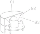
As shown in fig. 9, the light collecting cover 8 includes a glass sheet 81, a light collecting groove 82, and a light collecting cover body 83, the light collecting cover body 83 is a cylinder, the light collecting groove 82 is disposed on the upper end surface of the light collecting cover body 83, the light collecting groove 82 penetrates through the upper and lower end surfaces of the light collecting cover body 83, the light collecting groove 82 is an inverted truncated cone, the glass sheet 81 is fixed on the upper end surface of the light collecting cover body 83, and the lamp cap 71 is disposed inside the light collecting groove 82.
The working principle of the modern garden landscape night exploration equipment is as follows:
1) the invention is buried on the land under the garden landscape;
2) in daytime, when the photosensitive sensor on the rotation protection component 1 receives a strong light signal, a highlight signal is generated and transmitted to the circuit board 52, and the circuit board 52 supplies power to the driving motor 43 to enable the driving motor 43 to rotate reversely;
3) the driving motor 43 rotates reversely to drive the belt pulley 14 to rotate reversely, so as to drive the driving rotating shaft 15 to rotate reversely, so that the rotating blade group 11 is closed, and the lampshade is separated from the outside;
4) when the light sensor on the rotation protection component 1 receives no light or low-brightness signals at night, low-light signals are generated and transmitted to the circuit board 52, and the circuit board 52 supplies power to the driving motor 43, so that the driving motor 43 rotates forwards;
5) the driving motor 43 rotates forward to drive the belt pulley 14 to rotate forward, and further drives the driving rotating shaft 15 to rotate forward, so that the rotating blade set 11 is unfolded, the lampshade is exposed to the outside, meanwhile, the lamp head circuit board 75 supplies power to the lamp head 71, and the lamp head 71 illuminates the landscape, so that personnel can explore the garden landscape at night conveniently;
6) in sunny days, the photovoltaic panel on the rotary protection component 1 can collect light energy, convert the light energy into electric energy and store the electric energy in the storage battery 51;
7) in rainy days, rainwater enters the shell cover 22 through the filter screen 21, enters the lower half part of the inner side of the sealed shell 3 through the shell cover 22, then drives the water wheel blade 64 to rotate, and the water wheel blade 64 drives the generator rotor 63 to rotate, so that the micro generator 61 generates electric energy, and the electric energy is stored in the storage battery 51.
The foregoing is merely exemplary and illustrative of the present invention and various modifications, additions and substitutions may be made by those skilled in the art to the specific embodiments described without departing from the scope of the invention as defined in the following claims.
Claims (9)
1. The utility model provides a modernization landscape explores equipment at night, includes rotation protection subassembly (1), water catch bowl (2), seal shell (3), protection subassembly drive arrangement (4), power storage device (5), power generation facility (6), lamp stand (7) and collection light cover (8), its characterized in that, rotation protection subassembly (1) is fixed in on seal shell (3) up end, water catch bowl (2) cover in seal shell (3) lateral wall upside, and water catch bowl (2) and seal shell (3) lateral wall and rotation protection subassembly (1) lateral wall fixed connection, the inside and the inboard latter half of seal shell (3) of water catch bowl (2) link up and are connected, collection light cover (8) are embedded in seal shell (3) inside, and collection light cover (8) are located rotation protection subassembly (1) terminal surface down, lamp stand (7) are fixed embedded in on seal shell (3) inside wall, and lamp stand (7) up end and collection light cover (8) lower extreme fixed connection, lamp stand (7) upper end runs through collection light cover (8) lower extreme, sealed casing (3) bottom is located in protection subassembly drive arrangement (4), and protection subassembly drive arrangement (4) and rotatory protection subassembly (1) fixed connection, protection subassembly drive arrangement (4) upper end and power storage device (5) lower extreme fixed connection, and protection subassembly drive arrangement (4) and power storage device (5) electric connection, on power storage device (5) embedded being fixed in sealed casing (3) inside wall, power storage device (5) upper end is fixed with power generation facility (6), power generation facility (6) are embedded on the inside wall of the sealed casing (3) inboard the latter half.
2. The device for exploring the night in the modern garden landscape according to claim 1, wherein the rotary protection assembly (1) comprises a rotary blade set (11), a blade upper cover (12), a blade base (13), a belt pulley (14) and a driving rotating shaft (15), the rotary blade set (11) is composed of a plurality of blades, the plurality of blades are rotatably fixed between the blade upper cover (12) and the blade base (13) through the plurality of driving rotating shafts (15), the blade upper cover (12) is located on the upper side of the blade base (13), the plurality of blades are switched between a circular sealing structure and an opening structure through the plurality of driving rotating shafts (15), the lower ends of the plurality of driving rotating shafts (15) all penetrate through the upper end surface of the sealing shell (3) and extend to the lower side of the sealing shell (3), the belt pulley (14) is fixed on the lower ends of the plurality of driving rotating shafts (15), be equipped with photovoltaic board and photosensitive sensor on blade upper cover (12) the up end, photovoltaic board and photosensitive sensor all with circuit board (52) electric connection.
3. The modern landscape architecture night exploration equipment according to claim 1, wherein the water collection tank (2) comprises a filter screen (21) and a housing (22), the housing (22) is a hollow housing without a top and a bottom, the housing (22) is sleeved on the outer side wall of the sealing housing (3), the housing (22) is fixedly connected with the sealing housing (3), the filter screen (21) is of a circular ring shape, and the filter screen (21) is fixed on the upper end face of the housing (22) and is located between the edge of the upper end face of the housing (22) and the outer side wall of the blade upper cover (12).
4. The modern garden landscape night exploration device according to claim 1, wherein the seal housing (3) comprises a driving rotating shaft bearing hole (31), a water inlet through groove (32), a connecting support frame (33), a seal housing outer shell (34) and a seal housing inner shell (35), the seal housing outer shell (34) and the seal housing inner shell (35) are hollow cylinders without top and bottom, the seal housing inner shell (35) is sleeved inside the seal housing outer shell (34), the upper end edge of the seal housing inner shell (35) is fixedly connected with the upper end edge of the seal housing outer shell (34), the outer side wall of the seal housing outer shell (34) is in through connection with the inner side wall of the seal housing inner shell (35) through the water inlet through groove (32), the connecting support frame (33) is fixed on the inner side wall of the seal housing inner shell (35) and is located on the lower side of the inner side wall of the seal housing (35), the driving rotating shaft bearing hole (31) is formed between the edge of the upper end of the inner shell (35) of the sealing shell and the edge of the upper end of the outer shell (34) of the sealing shell, and the driving rotating shaft (15) is rotationally fixed in the driving rotating shaft bearing hole (31).
5. The device for exploring the night in the modern garden landscape according to claim 1, wherein the protection member driving means (4) comprises a driving housing bottom cover (41), a driving pulley (42), a driving motor (43), a driving belt (44), a driven pulley (45), a driven belt (46), a driving housing (47) and a sealing bottom cover (48), the driving housing (47) is fixed on the lower end face of the connecting support frame (33), the driving motor (43) is fixed on the inner side of the driving housing (47), the driving pulley (42) is fixed on the output shaft of the driving motor (43), the driving housing bottom cover (41) is fixed on the driving housing (47), the driven belt (46) is used for driving and connecting pulleys (14) at the lower ends of the plurality of driving shafts (15), the driven pulley (45) is fixed on the end of any one driving shaft (15) of the plurality of driving shafts (15), the driven belt pulley (45) is arranged between the sealing shell outer shell (34) and the sealing shell inner shell (35), the sealing bottom cover (48) is fixed between the lower end faces of the sealing shell outer shell (34) and the sealing shell inner shell (35), and the driven belt pulley (45) is in transmission connection with the driving belt pulley (42) through the driving belt (44).
6. The modern garden landscape night exploration device according to claim 1, wherein said power storage device (5) comprises a storage battery (51) and a circuit board (52), said storage battery (51) is mounted on the circuit board (52), the storage battery (51) is electrically connected with the circuit board (52), said circuit board (52) is fixed on the inner side wall of the driving shell (47), said circuit board (52) is fixed with a driving motor (43), said driving motor (43) is electrically connected with the circuit board (52), and said storage battery (51) is of a circular ring type.
7. The modern garden landscape night exploration equipment according to claim 1, wherein said power generation device (6) comprises a micro-generator (61), a generator fixing frame (62), a generator rotor (63) and water blades (64), said micro-generator (61) is fixed on the driving shell (47) through the generator fixing frame (62), said micro-generator (61) is electrically connected with the circuit board (52), and said water blades (64) are uniformly fixed on the generator rotor (63).
8. The night exploration equipment for the modern garden landscape according to claim 1, wherein the lamp holder (7) comprises a lamp holder (71), a lamp shell (72), a heat conduction fixing column (73), a heat conduction screw (74), a lamp holder circuit board (75), a lamp shell rear cover (76), a heat dissipation fin (77) and a lamp holder mounting seat (78), the lamp holder (71) is fixedly installed on the lamp holder mounting seat (78), the lamp holder mounting seat (78) is fixed on the lamp holder circuit board (75), the lamp holder (71) is electrically connected with the lamp holder circuit board (75), the lamp holder circuit board (75) is fixed on the inner side of the lamp shell (72) through the heat conduction fixing column (73), the heat dissipation fin (77) is fixed on the lower end face of the lamp shell rear cover (76), the lamp shell rear cover (76) is fixed on the lower end face of the lamp shell (72) through the heat conduction screw (74), the heat conducting screw (74) is in contact with the lamp cap circuit board (75).
9. The modern garden landscape night exploration device according to claim 1, wherein the light collecting cover (8) comprises a glass sheet (81), light gathering grooves (82) and a light collecting cover body (83), the light collecting cover body (83) is a cylinder, the light gathering grooves (82) are formed in the upper end face of the light collecting cover body (83), the light gathering grooves (82) penetrate through the upper end face and the lower end face of the light collecting cover body (83), the light gathering grooves (82) are inverted circular truncated cone-shaped, the glass sheet (81) is fixed on the upper end face of the light collecting cover body (83), and the lamp head (71) is arranged on the inner side of the light gathering grooves (82).
Priority Applications (1)
| Application Number | Priority Date | Filing Date | Title |
|---|---|---|---|
| CN202010475783.4A CN111578207B (en) | 2020-05-29 | 2020-05-29 | Modern garden landscape exploration equipment at night |
Applications Claiming Priority (1)
| Application Number | Priority Date | Filing Date | Title |
|---|---|---|---|
| CN202010475783.4A CN111578207B (en) | 2020-05-29 | 2020-05-29 | Modern garden landscape exploration equipment at night |
Publications (2)
| Publication Number | Publication Date |
|---|---|
| CN111578207A true CN111578207A (en) | 2020-08-25 |
| CN111578207B CN111578207B (en) | 2022-02-15 |
Family
ID=72112363
Family Applications (1)
| Application Number | Title | Priority Date | Filing Date |
|---|---|---|---|
| CN202010475783.4A Active CN111578207B (en) | 2020-05-29 | 2020-05-29 | Modern garden landscape exploration equipment at night |
Country Status (1)
| Country | Link |
|---|---|
| CN (1) | CN111578207B (en) |
Cited By (1)
| Publication number | Priority date | Publication date | Assignee | Title |
|---|---|---|---|---|
| CN112610911A (en) * | 2020-12-21 | 2021-04-06 | 潘俊旺 | Multifunctional lighting device suitable for outdoors |
Citations (5)
| Publication number | Priority date | Publication date | Assignee | Title |
|---|---|---|---|---|
| WO2005057620A2 (en) * | 2003-12-04 | 2005-06-23 | Essig John Raymond Jr | Modular inflatable multifunction field-deployable apparatus and methods of manufacture |
| CN104696866A (en) * | 2015-03-16 | 2015-06-10 | 成都赋阳技术开发有限公司 | Outdoor environment-friendly lighting device |
| CN106641756A (en) * | 2016-12-14 | 2017-05-10 | 鸿利智汇集团股份有限公司 | Deep ultraviolet LED with rotatable lampshade and using method |
| CN108278537A (en) * | 2018-04-02 | 2018-07-13 | 宁波华聪建筑节能科技有限公司 | A kind of lamps and lanterns with automatical cleaning ability |
| CN109163258A (en) * | 2018-09-10 | 2019-01-08 | 葛成燕 | A kind of LED lamp service life optimization method |
-
2020
- 2020-05-29 CN CN202010475783.4A patent/CN111578207B/en active Active
Patent Citations (5)
| Publication number | Priority date | Publication date | Assignee | Title |
|---|---|---|---|---|
| WO2005057620A2 (en) * | 2003-12-04 | 2005-06-23 | Essig John Raymond Jr | Modular inflatable multifunction field-deployable apparatus and methods of manufacture |
| CN104696866A (en) * | 2015-03-16 | 2015-06-10 | 成都赋阳技术开发有限公司 | Outdoor environment-friendly lighting device |
| CN106641756A (en) * | 2016-12-14 | 2017-05-10 | 鸿利智汇集团股份有限公司 | Deep ultraviolet LED with rotatable lampshade and using method |
| CN108278537A (en) * | 2018-04-02 | 2018-07-13 | 宁波华聪建筑节能科技有限公司 | A kind of lamps and lanterns with automatical cleaning ability |
| CN109163258A (en) * | 2018-09-10 | 2019-01-08 | 葛成燕 | A kind of LED lamp service life optimization method |
Cited By (1)
| Publication number | Priority date | Publication date | Assignee | Title |
|---|---|---|---|---|
| CN112610911A (en) * | 2020-12-21 | 2021-04-06 | 潘俊旺 | Multifunctional lighting device suitable for outdoors |
Also Published As
| Publication number | Publication date |
|---|---|
| CN111578207B (en) | 2022-02-15 |
Similar Documents
| Publication | Publication Date | Title |
|---|---|---|
| CN101949358B (en) | Wind and rain power generation system | |
| CN111578207B (en) | Modern garden landscape exploration equipment at night | |
| CN208380750U (en) | A kind of generation of electricity by new energy device | |
| CN202118763U (en) | Energy-saving street lamp | |
| CN205690267U (en) | Wind and solar energy LED street lamp | |
| CN213480102U (en) | Intelligent wind-solar hybrid street lamp | |
| CN215892216U (en) | Solar street lamp with follow-up device | |
| CN213577228U (en) | Multifunctional solar lamp | |
| CN213983354U (en) | Wind-solar complementary intelligent street lamp with dustproof structure | |
| CN114576093A (en) | Wind-powered electricity generation fan energy storage is enlarged and is utilized device | |
| CN210364269U (en) | Novel hydrological meteorological monitoring buoy | |
| CN207514765U (en) | A kind of energy saving and environment friendly LED street lamp | |
| CN216431548U (en) | Intelligent wind-solar complementary road lamp | |
| CN216198656U (en) | Wind generating set protector | |
| CN218237276U (en) | Wind-solar complementary street lamp | |
| CN213955196U (en) | Multifunctional solar street lamp | |
| CN220629301U (en) | Solar cell module with ventilation function | |
| CN216521386U (en) | Heat-dissipation energy-saving LED street lamp | |
| CN212840830U (en) | Dustproof device for LED solar lamp | |
| CN214038188U (en) | LED street lamp | |
| CN212012548U (en) | Solar energy electric quantity storage device for photovoltaic street lamp | |
| CN217354597U (en) | Wind driven generator convenient to install | |
| CN218929744U (en) | Multi-power multifunctional safety warning navigation mark for port | |
| CN215722971U (en) | Solar LED street lamp with protection function | |
| CN108844026A (en) | A kind of vertical axis integral-rotation type wind light mutual complementing power generation wind resistance snow street lamp |
Legal Events
| Date | Code | Title | Description |
|---|---|---|---|
| PB01 | Publication | ||
| PB01 | Publication | ||
| SE01 | Entry into force of request for substantive examination | ||
| SE01 | Entry into force of request for substantive examination | ||
| GR01 | Patent grant | ||
| GR01 | Patent grant |