CN111572346A - Intelligent high-voltage distribution box and working state monitoring method thereof - Google Patents
Intelligent high-voltage distribution box and working state monitoring method thereof Download PDFInfo
- Publication number
- CN111572346A CN111572346A CN202010436996.6A CN202010436996A CN111572346A CN 111572346 A CN111572346 A CN 111572346A CN 202010436996 A CN202010436996 A CN 202010436996A CN 111572346 A CN111572346 A CN 111572346A
- Authority
- CN
- China
- Prior art keywords
- interface
- voltage distribution
- distribution box
- box body
- monitoring
- Prior art date
- Legal status (The legal status is an assumption and is not a legal conclusion. Google has not performed a legal analysis and makes no representation as to the accuracy of the status listed.)
- Pending
Links
- 238000012544 monitoring process Methods 0.000 title claims abstract description 54
- 238000000034 method Methods 0.000 title claims abstract description 16
- 238000001514 detection method Methods 0.000 claims abstract description 40
- 238000004891 communication Methods 0.000 claims abstract description 31
- 230000005611 electricity Effects 0.000 claims description 7
- 238000005070 sampling Methods 0.000 claims description 4
- 238000004458 analytical method Methods 0.000 claims description 2
- 238000005259 measurement Methods 0.000 claims 1
- 238000012423 maintenance Methods 0.000 abstract description 5
- 206010048669 Terminal state Diseases 0.000 abstract description 2
- RYGMFSIKBFXOCR-UHFFFAOYSA-N Copper Chemical compound [Cu] RYGMFSIKBFXOCR-UHFFFAOYSA-N 0.000 description 11
- 229910052802 copper Inorganic materials 0.000 description 11
- 239000010949 copper Substances 0.000 description 11
- 238000010438 heat treatment Methods 0.000 description 8
- 238000004140 cleaning Methods 0.000 description 3
- 238000010586 diagram Methods 0.000 description 3
- 238000009434 installation Methods 0.000 description 3
- 230000036760 body temperature Effects 0.000 description 2
- 238000013024 troubleshooting Methods 0.000 description 2
- 238000009423 ventilation Methods 0.000 description 2
- 206010000369 Accident Diseases 0.000 description 1
- 101100194362 Schizosaccharomyces pombe (strain 972 / ATCC 24843) res1 gene Proteins 0.000 description 1
- 230000002159 abnormal effect Effects 0.000 description 1
- XAGFODPZIPBFFR-UHFFFAOYSA-N aluminium Chemical compound [Al] XAGFODPZIPBFFR-UHFFFAOYSA-N 0.000 description 1
- 229910052782 aluminium Inorganic materials 0.000 description 1
- 230000009286 beneficial effect Effects 0.000 description 1
- 238000006243 chemical reaction Methods 0.000 description 1
- 230000003111 delayed effect Effects 0.000 description 1
- 230000000694 effects Effects 0.000 description 1
- 230000002349 favourable effect Effects 0.000 description 1
- 230000010354 integration Effects 0.000 description 1
- 230000001681 protective effect Effects 0.000 description 1
- 238000011897 real-time detection Methods 0.000 description 1
- 230000000630 rising effect Effects 0.000 description 1
- 238000007789 sealing Methods 0.000 description 1
- 239000000779 smoke Substances 0.000 description 1
- XLYOFNOQVPJJNP-UHFFFAOYSA-N water Substances O XLYOFNOQVPJJNP-UHFFFAOYSA-N 0.000 description 1
Images





Classifications
-
- B—PERFORMING OPERATIONS; TRANSPORTING
- B60—VEHICLES IN GENERAL
- B60L—PROPULSION OF ELECTRICALLY-PROPELLED VEHICLES; SUPPLYING ELECTRIC POWER FOR AUXILIARY EQUIPMENT OF ELECTRICALLY-PROPELLED VEHICLES; ELECTRODYNAMIC BRAKE SYSTEMS FOR VEHICLES IN GENERAL; MAGNETIC SUSPENSION OR LEVITATION FOR VEHICLES; MONITORING OPERATING VARIABLES OF ELECTRICALLY-PROPELLED VEHICLES; ELECTRIC SAFETY DEVICES FOR ELECTRICALLY-PROPELLED VEHICLES
- B60L1/00—Supplying electric power to auxiliary equipment of vehicles
-
- B—PERFORMING OPERATIONS; TRANSPORTING
- B60—VEHICLES IN GENERAL
- B60L—PROPULSION OF ELECTRICALLY-PROPELLED VEHICLES; SUPPLYING ELECTRIC POWER FOR AUXILIARY EQUIPMENT OF ELECTRICALLY-PROPELLED VEHICLES; ELECTRODYNAMIC BRAKE SYSTEMS FOR VEHICLES IN GENERAL; MAGNETIC SUSPENSION OR LEVITATION FOR VEHICLES; MONITORING OPERATING VARIABLES OF ELECTRICALLY-PROPELLED VEHICLES; ELECTRIC SAFETY DEVICES FOR ELECTRICALLY-PROPELLED VEHICLES
- B60L3/00—Electric devices on electrically-propelled vehicles for safety purposes; Monitoring operating variables, e.g. speed, deceleration or energy consumption
-
- H—ELECTRICITY
- H02—GENERATION; CONVERSION OR DISTRIBUTION OF ELECTRIC POWER
- H02J—CIRCUIT ARRANGEMENTS OR SYSTEMS FOR SUPPLYING OR DISTRIBUTING ELECTRIC POWER; SYSTEMS FOR STORING ELECTRIC ENERGY
- H02J7/00—Circuit arrangements for charging or depolarising batteries or for supplying loads from batteries
- H02J7/0042—Circuit arrangements for charging or depolarising batteries or for supplying loads from batteries characterised by the mechanical construction
-
- H—ELECTRICITY
- H02—GENERATION; CONVERSION OR DISTRIBUTION OF ELECTRIC POWER
- H02J—CIRCUIT ARRANGEMENTS OR SYSTEMS FOR SUPPLYING OR DISTRIBUTING ELECTRIC POWER; SYSTEMS FOR STORING ELECTRIC ENERGY
- H02J7/00—Circuit arrangements for charging or depolarising batteries or for supplying loads from batteries
- H02J7/0047—Circuit arrangements for charging or depolarising batteries or for supplying loads from batteries with monitoring or indicating devices or circuits
-
- H—ELECTRICITY
- H02—GENERATION; CONVERSION OR DISTRIBUTION OF ELECTRIC POWER
- H02J—CIRCUIT ARRANGEMENTS OR SYSTEMS FOR SUPPLYING OR DISTRIBUTING ELECTRIC POWER; SYSTEMS FOR STORING ELECTRIC ENERGY
- H02J7/00—Circuit arrangements for charging or depolarising batteries or for supplying loads from batteries
- H02J7/0063—Circuit arrangements for charging or depolarising batteries or for supplying loads from batteries with circuits adapted for supplying loads from the battery
-
- Y—GENERAL TAGGING OF NEW TECHNOLOGICAL DEVELOPMENTS; GENERAL TAGGING OF CROSS-SECTIONAL TECHNOLOGIES SPANNING OVER SEVERAL SECTIONS OF THE IPC; TECHNICAL SUBJECTS COVERED BY FORMER USPC CROSS-REFERENCE ART COLLECTIONS [XRACs] AND DIGESTS
- Y02—TECHNOLOGIES OR APPLICATIONS FOR MITIGATION OR ADAPTATION AGAINST CLIMATE CHANGE
- Y02T—CLIMATE CHANGE MITIGATION TECHNOLOGIES RELATED TO TRANSPORTATION
- Y02T90/00—Enabling technologies or technologies with a potential or indirect contribution to GHG emissions mitigation
- Y02T90/10—Technologies relating to charging of electric vehicles
- Y02T90/16—Information or communication technologies improving the operation of electric vehicles
Landscapes
- Engineering & Computer Science (AREA)
- Power Engineering (AREA)
- Transportation (AREA)
- Mechanical Engineering (AREA)
- Life Sciences & Earth Sciences (AREA)
- Sustainable Development (AREA)
- Sustainable Energy (AREA)
- Connection Or Junction Boxes (AREA)
Abstract
The invention discloses an intelligent high-voltage distribution box and a working state monitoring method thereof, wherein the intelligent high-voltage distribution box comprises a box body and a box cover, wherein a battery power supply interface, a plurality of electric equipment interfaces and a low-voltage communication interface are arranged on the box body; through set up detection circuitry in the monitor cell to have detection fuse, relay state function: when the fuse breaks down, or when faults such as relay adhesion, unable actuation appear, can directly send electronic component's position and fault type to vehicle control unit through communication interface and bus, make vehicle control unit know the block terminal state in real time, can directly point out the fault point during the maintenance, guide maintainer to handle rapidly.
Description
Technical Field
The invention relates to the technical field of vehicle electrical equipment, in particular to an intelligent high-voltage distribution box and a working state monitoring method thereof.
Background
The high-voltage distribution box is a high-voltage and high-current distribution device of a new energy electric vehicle, a plug-in hybrid electric vehicle and the like, and is used for distributing electric energy of a battery to electric equipment such as a motor, an air conditioner, a DC/DC power supply, a heater and the like, almost all electric vehicles need to use the high-voltage distribution box, and the high-voltage distribution box can face the following problems in the using process:
firstly, the safety problem of electricity utilization. In recent years, electric vehicles represented by the Tesla brand have several serious fire accidents, and people have attracted extensive attention and worry about the use safety of the electric vehicles. Because the voltage of the power battery in the new energy electric automobile is very high, and the power battery is used as a junction between the power battery and the electric equipment, the internal environment of the high-voltage distribution box belongs to a high-voltage and high-current power utilization environment, and therefore, the power utilization safety of the high-voltage distribution box is very important for the power utilization safety of the whole automobile.
And secondly, the problem of fault detection. Because the high-voltage distribution box is positioned at the pivot position between the power battery and the electric equipment and is in a high-voltage and high-current power utilization state, the failure rate of internal electronic elements is relatively high, and the high-voltage distribution box has more electronic elements and is more laborious in troubleshooting.
For the above reasons, there is a need for a high voltage distribution box with higher safety and convenient troubleshooting.
Disclosure of Invention
The invention aims to provide an intelligent high-voltage distribution box and a working state monitoring method thereof, and solves the technical problem that the working state monitoring of the high-voltage distribution box in the prior art is not accurate enough.
To solve the above technical problem, a first aspect of the present invention is:
the utility model provides an intelligence high voltage distribution box, includes box body, lid, be equipped with battery power supply interface, a plurality of consumer interface and low pressure communication interface on the box body, be equipped with the electricity in the box body battery power supply interface and each the power distribution circuit of consumer interface, power distribution circuit includes a plurality of fuses and relay still be equipped with the monitor cell in the box body, the monitor cell is including the temperature sensor that corresponds treater, communication module and a plurality of distribution that the electricity is connected and set up, the treater acquires and analyzes respectively temperature sensor measuring temperature information, communication module output end electric connection to low pressure communication interface, thereby can export the final temperature information that the treater analysis obtained.
Preferably, the monitoring unit further comprises a detection circuit for monitoring the working electrical signals of the fuse and the relay and the control electrical signals of the relay respectively, and the detection circuit is electrically connected with the processor respectively.
Preferably, the monitoring unit further comprises an interlocking monitor for monitoring the closing state of the box body and the box cover and the plugging state of the battery power supply interface or/and the electric equipment interface; be equipped with interlock switch between box body and the lid, correspond on battery power supply interface or/and the consumer interface and be equipped with two interlock binding post, connect electrically after establishing ties between interlock switch, the interlock binding post and connect to the interlock monitor.
Preferably, a monitoring circuit board is arranged in the box body, the processor, the temperature sensors, the communication module, the interlock monitor and the detection circuits are all arranged on the monitoring circuit board, and the temperature sensors are distributed on the monitoring circuit board;
the monitoring circuit board and the power distribution circuit are arranged on the circuit board and the supporting plate.
Preferably, the detection circuit is a voltage sampling circuit.
The second aspect of the present invention is:
the method for monitoring the working state of the intelligent high-voltage distribution box comprises the following steps: the monitoring unit is arranged in the box body of the high-voltage distribution box and comprises a processor, a communication module and a plurality of temperature sensors which are electrically connected correspondingly, the average value of the temperature measured by each temperature sensor is obtained and calculated through the processor, and the average value information of the temperature is sent to the whole vehicle controller in real time.
Preferably, the method further comprises the following steps: whether the fuse and the relay in the intelligent high-voltage distribution box break down or not and the power-on state of the relay are detected in real time through a detection circuit, and a detection result is sent to the whole vehicle controller in real time.
Preferably, the method further comprises the following steps: the box body and the cover closing state of the high-voltage distribution box and the plugging state of the battery power supply interface or/and the electric equipment interface are monitored through the interlocking monitor, and the detection result is sent to the vehicle control unit in real time.
The invention has the beneficial technical effects that:
1. according to the intelligent high-voltage distribution box provided by the invention, the plurality of temperature sensors are arranged in the monitoring unit, so that the temperature information in the box body can be timely and accurately monitored and fed back to the whole vehicle controller, and the situation that the temperature information in the box body cannot be timely fed back or wrong judgment is brought due to local temperature difference in the box body is prevented.
2. Through set up detection circuitry in the monitor cell to have detection fuse, relay state function: when the fuse breaks down, or when faults such as relay adhesion, unable actuation appear, can directly send electronic component's position and fault type to vehicle control unit through communication interface and bus, make vehicle control unit know the block terminal state in real time, can directly point out the fault point during the maintenance, guide maintainer to handle rapidly.
3. Between this intelligence high voltage distribution box's the box body and the lid, and be equipped with interlocking circuit between each consumer interface, realize the interlocking and detect the function, the interlocking monitor uses PWM (pulse) form to send to in the interlocking return circuit, the real-time detection interlocking state, can in time monitor the lid condition of closing of box body and lid, and each consumer interface intercommunication condition, can directly take place to send to vehicle control unit through communication interface and bus with the connector position that will not insert in place, can directly point out the fault point accuracy during the maintenance, guide the maintenance personal to handle rapidly.
Drawings
Fig. 1 is a schematic perspective view of an intelligent high-voltage distribution box according to an embodiment of the present invention.
Fig. 2 is a schematic diagram of an internal structure of an embodiment of the intelligent high-voltage distribution box according to the invention.
Fig. 3 is a front view of an embodiment of the intelligent high voltage distribution box of the present invention.
Fig. 4 is a rear view of an embodiment of the intelligent high voltage distribution box of the present invention.
Fig. 5 is a top view of the intelligent high-voltage distribution box according to the embodiment of the invention in an open state.
Fig. 6 is a top view of the intelligent high-voltage distribution box according to the embodiment of the invention, in a state of opening the cover, without installing the monitoring circuit board.
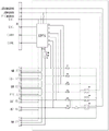
Fig. 7 is a schematic circuit diagram of an embodiment of the intelligent high-voltage distribution box of the present invention.
Fig. 8 is a circuit block diagram of a monitoring unit in an embodiment of the intelligent high voltage distribution box of the present invention.
Fig. 9 is a left side view of an embodiment of the intelligent high voltage distribution box of the present invention.
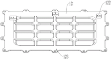
Fig. 10 is a schematic perspective view of a box cover in a bottom view direction in an embodiment of the intelligent high-voltage distribution box of the invention.
Fig. 11 is a top view of an embodiment of the intelligent high voltage distribution box of the present invention.
In the drawings, each reference numeral means: the device comprises a box body 11, an annular groove 111, a connecting lug 112, a bonding wire 113, an installation lug seat 114, a circuit board 115, a supporting plate 116, a positioning column 117, a travel switch support column 118, a waterproof ventilation valve 119, a box cover 12, a screw 121, a travel switch support column installation surface 122, a positioning bulge 123, a positioning hole 1231, a traceability mark 124, a recyclable mark 125, a high-voltage warning mark 126, a battery power supply interface 21, a positive copper strip 211, a negative copper strip 212, an A/C interface 22, an MCU interface 23, a three-in-one interface 24, a heating power supply PTC interface 25, a first upper mounting interface 26, a second upper mounting interface 27, a low-voltage communication interface 28, a PTC relay 31, an upper mounting relay 32, an upper pre-charging relay 33, a pre-charging resistor 34 and a monitoring circuit board 4.
Detailed Description
The following examples are intended to illustrate the present invention in detail and should not be construed as limiting the scope of the present invention in any way.
In the description of the present invention, it is to be understood that the terms "upper", "lower", "front", "rear", "left", "right", "top", "bottom", "inner", "outer", and the like, indicate orientations or positional relationships based on the orientations or positional relationships shown in the drawings, are merely for convenience in describing the present invention and simplifying the description, and do not indicate or imply that the device or element being referred to must have a particular orientation, be constructed and operated in a particular orientation, and thus, should not be construed as limiting the present invention. References to "first," "second," etc. (if any) in this application are intended to distinguish between similar elements and not necessarily to describe a particular order or sequence.
Example 1:
an intelligent high-voltage distribution box is disclosed, and fig. 1 to 11 are also disclosed.
The intelligent high-voltage distribution box provided by the embodiment of the invention comprises a protective shell consisting of a box body 11 and a box cover 12, wherein an annular groove 111 is arranged on the contact surface of the top of the box body 11 and the box cover 12, a rubber ring is arranged in the annular groove 111, and the box cover 12 is covered on the box body 11 to form sealing. The edges of the box body 11 and the box cover 12 are provided with a plurality of convex connecting lugs 112, the connecting lugs 112 are correspondingly provided with screw holes, and the box body 11 and the box cover 12 are connected with each other through screws 121 screwed on the connecting lugs 112. The box body 11 and the box cover 12 are made of cast aluminum, have shielding performance, can stand the change of the working environment temperature (-40 ℃ to + 125 ℃), and have no shrinkage and no layer rising phenomenon. The outer surface of the bottom of the box body 11 is also connected with a bonding wire 113 through a screw to ensure the safety of electricity utilization, and the side surface of the box body 11 is provided with a waterproof ventilation valve 119. The case 11 is provided at both sides thereof with mounting lugs 114, respectively, for mounting the high voltage distribution box at a fixed position on the vehicle.
As shown in fig. 2 and 3, a battery power supply interface 21 and a plurality of electrical device interfaces are provided on the box body 11, the battery power supply interface 21 is located on the back of the box body 11 and is used for connecting the output end of the battery, and the battery power is distributed to each electrical device through the electrical device interfaces.
In the embodiment, the electric equipment interface comprises an A/C interface 22 for supplying power to an air conditioner, an MCU interface 23 for supplying power to a driving motor, a three-in-one interface 24, a heating power supply PTC interface 25, a first upper mounting interface 26 and a second upper mounting interface 27, wherein the first upper mounting interface 26 comprises two separated interfaces RES 1-and RES1 +. The intelligent high-voltage distribution box is suitable for special vehicles, such as sanitation vehicles with water sprinkling and cleaning functions or garbage cleaning and transporting vehicles, and the first loading interface 26 and the second loading interface 27 are used for supplying power to devices which are not equipped by conventional vehicles, such as motors of various devices on the vehicles, such as booster pumps, cleaning brushes and the like, and pump stations of hydraulic systems. The three-in-one interface 24 is used for supplying power to a DC-DC direct current conversion device, a vehicle-mounted charger, a distribution box and the like.
Correspondingly, a power distribution circuit electrically connecting the battery power supply interface 21 and each electrical device interface is arranged in the box body 11, and the power distribution circuit comprises wires electrically connecting the battery power supply interface 21 and each electrical device interface, and some electronic elements such as fuses, relay resistors and the like arranged on the wires.
As shown in fig. 5, a positive copper bar 211 and a negative copper bar 212 electrically connected to the battery power supply interface 21 are provided in the case 11, and circuits corresponding to the respective electric equipment interfaces are respectively connected to the terminal ends of the corresponding fuses or relays in a lap joint manner via the corresponding copper bars. Taking the circuit corresponding to the MCU interface 23 as an example, one end of the fuse FU1 corresponding to the MCU interface 23 is connected to the positive copper bar 211, the other end is connected to the positive terminal of the MCU interface 23 through the copper bar 231, and the negative copper bar 212 is directly electrically connected to the negative terminal of the MCU interface 23. The connection mode of the circuits corresponding to the other electric equipment interfaces is the same as the principle of the MCU interface 23, and the description is omitted. In the embodiment, the surfaces of the copper bars are plated with stannous, and the surfaces of the copper bars and the corresponding end mounting surfaces of the fuses are required to be kept flush, level, smooth and clean, so that enough contact area is ensured; and the inner hole and the outer edge of the flat gasket matched with the bolt for fixing the copper bar are free of burrs, so that the burrs are prevented from being burnt by large current.
As shown in fig. 5, a fuse FU3, a fuse FU1, a fuse FU2, a fuse FU4, a fuse FU5 and a fuse FU6 are arranged on the circuit respectively corresponding to the a/C interface 22, the MCU interface 23, the three-in-one interface 24, the heating power supply PTC interface 25, the first upper mounting interface 26 and the second upper mounting interface 27, and the fuse corresponding to the rated current is selected according to the load condition connected by the corresponding interface. As shown in fig. 6 and 7, the PTC relay 31 (KM 1) is provided on the circuit corresponding to the heating power supply PTC interface 25, and the upper relay 32 (KM 2) and the upper precharge relay 33 (KM 3) are provided on the circuit corresponding to the first upper interface 26 and the second upper interface 27.
Further, a pre-charge resistor 34 (resistor R) is electrically connected to an output terminal of the main circuit of the upper pre-charge relay 33, and the pre-charge resistor 34 and an output terminal of the main circuit of the upper relay 32 are electrically connected to input terminals of a fuse FU5 connected to the first upper interface 26 and a fuse FU6 connected to the second upper interface 27. The upper charging relay 32 (KM 2) and the upper charging pre-charging relay 33 (KM 3) are matched for use, in the using process, the upper charging relay 32 (KM 2) is firstly switched off, the upper charging pre-charging relay 33 (KM 3) is switched on, a pre-charging loop formed by the upper charging pre-charging relay 33 (KM 3) and a pre-charging resistor 34 (resistor R) is firstly switched on, and the pre-charging resistor 34 can effectively reduce loop current and prevent the upper charging pre-charging relay 33 from being burnt out, so that loads connected with the first upper charging interface 26 and the second upper charging interface 27 can be charged; then the upper charging relay 32 is closed, and because the upper charging pre-charging relay 33 is closed firstly, the instantaneous current when the upper charging relay 32 is closed is reduced, and the phenomena of burning out, such as adhesion and the like, of the upper charging relay 32 are prevented.
As shown in fig. 7, the low-voltage communication interface 28 is further disposed on the side surface of the box body 11, and the interfaces J1, J2, J3, J4, J5, J6, J7, and J8 are respectively an MCU interface 23, a three-in-one interface 24, an a/C interface 22, a heating power supply PTC interface 25, a first upper mounting interface 26, a second upper mounting interface 27, a battery power supply interface 21, and a low-voltage communication interface 28 on the high-voltage distribution box, the positive electrodes of the control circuits of the PTC relay 31 (KM 1), the upper mounting relay 32 (KM 2), and the upper mounting pre-charging relay 33 (KM 3) are commonly connected to the pin 15 of the low-voltage communication interface, the negative electrodes are respectively connected to the pins 4, 7, and 5 of the low-voltage communication interface, the low-voltage communication interface 28 is used for connecting to a vehicle controller, and the vehicle controller can send a control signal to the high.
Further, still be equipped with the monitoring unit in box body 11, the monitoring unit is including the treater that corresponds the electricity and connects, communication module and a plurality of temperature sensor that distribute the setting, in this embodiment, be equipped with monitoring circuit board 4, monitoring unit electronic components and relevant circuit integration are on monitoring circuit board 4, wherein, six total temperature sensor, six temperature sensor distribute in monitoring circuit board 4 different positions, be used for sampling the temperature of different positions, in other embodiments, also can arrange temperature sensor in box body different positions, be not restricted to and arrange on monitoring circuit board.
Each temperature sensor is electrically connected with the processor, the processor is a single chip microcomputer, and the processor acquires and analyzes temperature information measured by each temperature sensor, for example, the processor calculates the average value or the maximum value of the six temperature sensors; the communication module is a CAN interface chip, the communication module is electrically connected to the processor, and the output end corresponds to the pin 10 (CANH pin) and the pin 11 (CANL pin) electrically connected to the low-voltage communication interface 28, so that the final temperature information analyzed by the processor CAN be output.
Through setting up a plurality of temperature sensor, be favorable to timely accurate monitoring box body temperature information and feed back vehicle control unit, prevent that local temperature difference in the box body from causing and can not in time feed back box body temperature information or bring the misjudgment. If the feedback is not timely, the early warning time is delayed, the lighter distribution box generates smoke, and the heavier distribution box causes the vehicle to be on fire; if misjudgment is brought, unnecessary work such as parking, maintenance and the like can be caused.
Further, the monitoring unit further includes a detection circuit for monitoring the working electrical signals of the fuse and the relay and the control electrical signals of the relay, as shown in fig. 8, in this embodiment, the detection circuit includes four low voltage detection circuits and six high voltage detection circuits, which are all voltage sampling circuits.
As shown in fig. 7, the four low voltage detection circuits in the monitoring unit are respectively and correspondingly electrically connected to the control circuit cathodes (pins 4, 7 and 5 of the low voltage communication interface) of the PTC relay 31 (KM 1), the upper relay 32 (KM 2) and the upper pre-charging relay 33 (KM 3) and the public power supply terminal (pin 15 of the low voltage communication interface), and by arranging the low voltage detection circuits, the monitoring unit can be used for detecting whether the corresponding relays are closed or not, and whether the corresponding relays are functional or not, and judging whether the working signal supplied from the outside of the high voltage distribution box is successfully received or not. The measuring terminals (P1-P6) of the six high-voltage detection circuits are respectively and electrically connected to the output terminals of the fuses (FU 1-FU 6), and if a certain fuse is fused, the corresponding high-voltage detection circuit can detect voltage abnormity.
The detection circuits are respectively electrically connected with the processor, the processor acquires detection information of the detection circuits and sends the detection information to the vehicle controller of the vehicle through the communication interface, so that the vehicle controller monitors the voltage of each electric equipment interface, the power-on state and the power-off state of each relay in real time to realize the fusing alarm function of the fuse, and the vehicle controller can be connected with an alarm or a screen to display related information on the screen or alarm and remind through the alarm.
Furthermore, the monitoring unit further comprises an interlocking monitor for monitoring the covering state of the box body 11 and the box cover 12 and the plugging state of the battery power supply interface 21 and part of the electric equipment interfaces.
Referring to fig. 2 and 10, an interlock switch K is disposed between the case body 11 and the case cover 12, and includes a travel switch support 118 disposed inside the case body 11, a travel switch support mounting surface 122 disposed on a lower surface of the case cover 12, and the travel switch support 118 and the travel switch support mounting surface 122 are electrically connected to an interlock terminal of the interlock monitor and the battery power supply interface 21 (J7 interface in fig. 7), respectively.
The lower surface of the box cover 12 is also provided with a positioning bulge 123, and the upper edge of the box body 11 is correspondingly provided with a positioning hole 1231, so that the alignment installation is convenient. Two interlocking wiring terminals are correspondingly arranged on the battery power supply interface 21, the MCU interface 23, the three-in-one interface 24, the A/C interface 22 and the heating power supply PTC interface 25 (no number marked on the corresponding interface is the interlocking wiring terminal, and numbers marked 1 and 2 are main circuit terminals). Referring to fig. 7, the two ends of the interlock switch K, the battery power supply interface 21 (J7), the MCU interface 23 (J1), the three-in-one interface 24 (J2), the a/C interface 22 (J3), and the interlock terminals of the heating power supply PTC interface 25 (J3) are connected in series and then electrically connected to the interlock monitor, forming an interlock detection circuit (HVIL).
When box body 11, lid 12 lid closes and makes interlock switch K closed, and battery powered interface 21, MCU interface 23, trinity interface 24, A/C interface 22, heating power supply PTC interface 25 all pegs graft with the plug of the consumer that corresponds back, the interlock monitor is regularly to interlock detection circuitry send voltage signal, whether monitoring interlock detection circuitry switches on, if switch on, then show box body 11, lid 12 lid closes well, and the consumer interface grafting state that corresponds is good, if not switch on, then show box body 11, lid 12 does not close, or at least a certain one of them consumer interface does not peg graft and connects.
Further, a circuit board 115 is provided at an upper portion of the case 11, a support plate 116 is provided at a lower portion thereof, and the monitoring circuit board 4 and the power distribution circuit are disposed on the circuit board 115 and the support plate 116.
The bottom in the box body 11 is provided with a hollow stud for supporting the supporting plate 116, and the supporting plate 116 is mounted on the hollow stud through a screw. A supporting column is arranged between the circuit board 115 and the supporting plate 116, so that the circuit board 115 is supported on the supporting plate 116, in addition, a plurality of positioning columns 117 are also arranged on the supporting plate 116, the fuses FU1 and FU5 are directly arranged on the two positioning columns 117, and the fuses FU3, FU2, FU4 and FU6 are arranged on the circuit board 115.
The size of the supporting plate 116 is close to the area inside the box body 11, and the size of the circuit board 115 is close to half of the area inside the box body 11, so that mounting surfaces with different sizes and matching heights are formed, and the electrical elements can be conveniently arranged and connected in the box body 11.
In addition, a traceability mark 124 is arranged on the box cover 12 of the high-voltage distribution box, an obvious recyclable mark 125 is arranged at the upper left corner, and a high-voltage warning mark 126 is arranged at the middle part.
Example 2:
an operating state monitoring method of an intelligent high-voltage distribution box adopts the intelligent high-voltage distribution box in embodiment 1, and the method comprises the following steps:
temperature monitoring: the monitoring unit is arranged in the box body of the high-voltage distribution box and comprises a processor, a communication module and six temperature sensors which are electrically connected correspondingly, the average value of the temperature measured by each temperature sensor is obtained and calculated through the processor, and the average value information of the temperature is sent to the whole vehicle controller in real time.
Monitoring electrical components: whether the fuse and the relay in the intelligent high-voltage distribution box break down or not and the power-on state of the relay are detected in real time through the detection circuit, and a detection result is sent to the vehicle control unit in real time.
Interlocking monitoring: the box body and the cover closing state of the high-voltage distribution box and the plugging state of the battery power supply interface or/and the electric equipment interface are monitored through the interlocking monitor, and the detection result is sent to the vehicle control unit in real time.
The method can be used for fault self-detection of a high-voltage distribution box of a vehicle: the temperature in the box body is detected in time through the temperature sensor, and when certain electronic element in the high-voltage distribution box is in an operating state, a related detection circuit in the monitoring unit also operates. The high-voltage distribution box can continuously perform fault self-detection so as to monitor temperature information in the box body and abnormal events of each electronic element in the running state, if the detected faults are regarded as potential risks (such as overhigh temperature and overhigh voltage), necessary measures (such as stopping power supply of the corresponding electronic elements and stopping the whole distribution box to supply power) must be taken to ensure safety, and the vehicle using safety is improved.
While the present invention has been described in detail with reference to the drawings and the embodiments, those skilled in the art will understand that various specific parameters in the above embodiments can be changed without departing from the spirit of the present invention, and a plurality of specific embodiments are formed, which are common variation ranges of the present invention, and will not be described in detail herein.
Claims (8)
1. The utility model provides an intelligence high voltage distribution box, includes box body, lid, be equipped with battery power supply interface, a plurality of consumer interface and low pressure communication interface on the box body, be equipped with the electricity in the box body battery power supply interface and each the power distribution circuit of consumer interface, power distribution circuit includes a plurality of fuses and relay, a serial communication port still be equipped with the monitor cell in the box body, the monitor cell is including the temperature sensor who corresponds treater, communication module and a plurality of distribution setting of electricity connection, the treater acquires and analyzes respectively the temperature information of temperature sensor measurement, the communication module output end electric connection to low pressure communication interface, thereby can export the final temperature information that the treater analysis obtained.
2. The intelligent high voltage distribution box according to claim 1, wherein said monitoring unit further comprises detection circuits for monitoring the operating electrical signals of said fuse and relay and the control electrical signals of said relay, respectively, said detection circuits being electrically connected to said processor, respectively.
3. The intelligent high voltage distribution box according to claim 2, wherein the monitoring unit further comprises an interlock monitor for monitoring the state of the box body, the cover and the battery power supply interface or/and the electric equipment interface; be equipped with interlock switch between box body and the lid, correspond on battery power supply interface or/and the consumer interface and be equipped with two interlock binding post, connect electrically after establishing ties between interlock switch, the interlock binding post and connect to the interlock monitor.
4. The intelligent high voltage distribution box according to claim 3, wherein a monitoring circuit board is disposed in the box body, the processor, the temperature sensors, the communication module, the interlock monitor and each detection circuit are disposed on the monitoring circuit board, and each temperature sensor is disposed on the monitoring circuit board;
the monitoring circuit board and the power distribution circuit are arranged on the circuit board and the supporting plate.
5. The intelligent high voltage distribution box according to claim 2, wherein the detection circuit is a voltage sampling circuit.
6. A working state monitoring method of an intelligent high-voltage distribution box is characterized by comprising the following steps: the monitoring unit is arranged in the box body of the high-voltage distribution box and comprises a processor, a communication module and a plurality of temperature sensors which are electrically connected correspondingly, the average value of the temperature measured by each temperature sensor is obtained and calculated through the processor, and the average value information of the temperature is sent to the whole vehicle controller in real time.
7. The method of monitoring the operational status of an intelligent high voltage distribution box according to claim 6, further comprising: whether the fuse and the relay in the intelligent high-voltage distribution box break down or not and the power-on state of the relay are detected in real time through a detection circuit, and a detection result is sent to the whole vehicle controller in real time.
8. The method of monitoring the operational status of an intelligent high voltage distribution box according to claim 6, further comprising: the box body and the cover closing state of the high-voltage distribution box and the plugging state of the battery power supply interface or/and the electric equipment interface are monitored through the interlocking monitor, and the detection result is sent to the vehicle control unit in real time.
Priority Applications (1)
| Application Number | Priority Date | Filing Date | Title |
|---|---|---|---|
| CN202010436996.6A CN111572346A (en) | 2020-05-21 | 2020-05-21 | Intelligent high-voltage distribution box and working state monitoring method thereof |
Applications Claiming Priority (1)
| Application Number | Priority Date | Filing Date | Title |
|---|---|---|---|
| CN202010436996.6A CN111572346A (en) | 2020-05-21 | 2020-05-21 | Intelligent high-voltage distribution box and working state monitoring method thereof |
Publications (1)
| Publication Number | Publication Date |
|---|---|
| CN111572346A true CN111572346A (en) | 2020-08-25 |
Family
ID=72123318
Family Applications (1)
| Application Number | Title | Priority Date | Filing Date |
|---|---|---|---|
| CN202010436996.6A Pending CN111572346A (en) | 2020-05-21 | 2020-05-21 | Intelligent high-voltage distribution box and working state monitoring method thereof |
Country Status (1)
| Country | Link |
|---|---|
| CN (1) | CN111572346A (en) |
Cited By (1)
| Publication number | Priority date | Publication date | Assignee | Title |
|---|---|---|---|---|
| WO2022257022A1 (en) * | 2021-06-08 | 2022-12-15 | Abb Schweiz Ag | Electrical module and associated backplane |
Citations (6)
| Publication number | Priority date | Publication date | Assignee | Title |
|---|---|---|---|---|
| CN203800515U (en) * | 2014-01-27 | 2014-08-27 | 上汽通用五菱汽车股份有限公司 | High-voltage power distribution box with interlocking protection function |
| CN205985767U (en) * | 2016-05-24 | 2017-02-22 | 北京京润海自动化技术研究所 | Block terminal with fire control function |
| CN107585033A (en) * | 2017-09-13 | 2018-01-16 | 北汽银翔汽车有限公司 | A kind of automotive intelligent type high voltage control box |
| WO2018176674A1 (en) * | 2017-04-01 | 2018-10-04 | 上海蔚来汽车有限公司 | High voltage distribution box for use in electric vehicle, electrical control system, and electric vehicle |
| CN208602327U (en) * | 2018-08-15 | 2019-03-15 | 河南航瑞电子科技有限公司 | A kind of new-energy automobile high voltage distribution box |
| CN212267233U (en) * | 2020-05-21 | 2021-01-01 | 河南航瑞电子科技有限公司 | Intelligent high-voltage distribution box |
-
2020
- 2020-05-21 CN CN202010436996.6A patent/CN111572346A/en active Pending
Patent Citations (6)
| Publication number | Priority date | Publication date | Assignee | Title |
|---|---|---|---|---|
| CN203800515U (en) * | 2014-01-27 | 2014-08-27 | 上汽通用五菱汽车股份有限公司 | High-voltage power distribution box with interlocking protection function |
| CN205985767U (en) * | 2016-05-24 | 2017-02-22 | 北京京润海自动化技术研究所 | Block terminal with fire control function |
| WO2018176674A1 (en) * | 2017-04-01 | 2018-10-04 | 上海蔚来汽车有限公司 | High voltage distribution box for use in electric vehicle, electrical control system, and electric vehicle |
| CN107585033A (en) * | 2017-09-13 | 2018-01-16 | 北汽银翔汽车有限公司 | A kind of automotive intelligent type high voltage control box |
| CN208602327U (en) * | 2018-08-15 | 2019-03-15 | 河南航瑞电子科技有限公司 | A kind of new-energy automobile high voltage distribution box |
| CN212267233U (en) * | 2020-05-21 | 2021-01-01 | 河南航瑞电子科技有限公司 | Intelligent high-voltage distribution box |
Cited By (1)
| Publication number | Priority date | Publication date | Assignee | Title |
|---|---|---|---|---|
| WO2022257022A1 (en) * | 2021-06-08 | 2022-12-15 | Abb Schweiz Ag | Electrical module and associated backplane |
Similar Documents
| Publication | Publication Date | Title |
|---|---|---|
| CN212267233U (en) | Intelligent high-voltage distribution box | |
| WO2018064861A1 (en) | Dual-connector electric car direct current charging pile | |
| CN202593301U (en) | Universal high-voltage safety control device for electric vehicle | |
| CN103078357B (en) | Intelligent vehicle-mounted high-voltage power distribution management unit for electric vehicle | |
| CN113291156B (en) | High-voltage power distribution system of pure electric vehicle | |
| CN208867977U (en) | The commercial automobile-used high-voltage electric device of new energy | |
| CN109813985B (en) | Electric automobile fills electric pile testing arrangement | |
| CN108790829A (en) | A kind of high voltage loop of electric automobile Detection & Controling circuit and detection method | |
| CN111572346A (en) | Intelligent high-voltage distribution box and working state monitoring method thereof | |
| CN211043526U (en) | New energy automobile high voltage distributor box detection device | |
| CN106114417B (en) | The low-voltage distribution box of pure electric coach | |
| CN205581221U (en) | Electric automobile direct current fills electric pile interface circuit simulator | |
| CN117261643B (en) | Charging pile and working method thereof | |
| CN212171939U (en) | New energy automobile power management system | |
| CN202319944U (en) | Electric power management device for electric vehicle | |
| CN216251717U (en) | Intelligent charging power supply power distribution cabinet with circuit protection function | |
| CN216545761U (en) | High-power direct current fills electric pile | |
| CN114919437A (en) | Lithium electric forklift charging system and method | |
| CN214958134U (en) | High-voltage distribution box | |
| CN214492774U (en) | Universal double-branch high-voltage distribution box | |
| CN110014934A (en) | A kind of integral type is double to fill direct-current charging post | |
| CN111361421A (en) | New energy automobile power management system | |
| CN209250225U (en) | A kind of modularization intelligent power distribution managing device | |
| CN111572347A (en) | Intelligent storage battery compartment distribution box for hydrogen energy vehicle and use method thereof | |
| CN205871947U (en) | Electric automobile controller and electric automobile |
Legal Events
| Date | Code | Title | Description |
|---|---|---|---|
| PB01 | Publication | ||
| PB01 | Publication | ||
| SE01 | Entry into force of request for substantive examination | ||
| SE01 | Entry into force of request for substantive examination |