CN111571731B - Straight edge machine for wood processing with stable cutting and convenient adjustment - Google Patents
Straight edge machine for wood processing with stable cutting and convenient adjustment Download PDFInfo
- Publication number
- CN111571731B CN111571731B CN202010481035.7A CN202010481035A CN111571731B CN 111571731 B CN111571731 B CN 111571731B CN 202010481035 A CN202010481035 A CN 202010481035A CN 111571731 B CN111571731 B CN 111571731B
- Authority
- CN
- China
- Prior art keywords
- sliding
- fixedly connected
- motor
- cutting
- bolt
- Prior art date
- Legal status (The legal status is an assumption and is not a legal conclusion. Google has not performed a legal analysis and makes no representation as to the accuracy of the status listed.)
- Active
Links
Images


Classifications
-
- B—PERFORMING OPERATIONS; TRANSPORTING
- B27—WORKING OR PRESERVING WOOD OR SIMILAR MATERIAL; NAILING OR STAPLING MACHINES IN GENERAL
- B27C—PLANING, DRILLING, MILLING, TURNING OR UNIVERSAL MACHINES FOR WOOD OR SIMILAR MATERIAL
- B27C5/00—Machines designed for producing special profiles or shaped work, e.g. by rotary cutters; Equipment therefor
- B27C5/02—Machines with table
- B27C5/06—Arrangements for clamping or feeding work
Landscapes
- Life Sciences & Earth Sciences (AREA)
- Engineering & Computer Science (AREA)
- Mechanical Engineering (AREA)
- Wood Science & Technology (AREA)
- Forests & Forestry (AREA)
- Milling, Drilling, And Turning Of Wood (AREA)
Abstract
The invention discloses a straight edge machine for wood processing, which is stable in cutting and convenient to adjust, and comprises a bottom plate, a first motor, a second motor and an electric telescopic rod, wherein the first motor is fixedly arranged on the side wall of the bottom plate, the upper end of the bottom plate is provided with a first sliding mechanism, the tail end of an output shaft of the first motor is fixedly connected with the driving end of the first sliding mechanism, the movable end of the first sliding mechanism is provided with an adjusting mechanism, the movable end of the adjusting mechanism is provided with a cutting mechanism, the second motor is fixedly arranged on the movable end of the adjusting mechanism and is fixedly connected with the driving end of the cutting mechanism, the upper end of the bottom plate is fixedly connected with a gantry support, the upper end of the gantry support is provided with a second sliding mechanism, and the same transmission mechanism is arranged between the driving end of the second sliding mechanism and the output shaft of the first motor. The invention not only can effectively improve the stability of wood cutting, but also can effectively adjust the width of the wood cutting.
Description
Technical Field
The invention relates to the technical field of wood processing, in particular to a straight edge machine for wood processing, which is stable in cutting and convenient to adjust.
Background
Timber is the plant that can secondary growth, timber plays very big supporting role to human life, according to the different nature characteristics of timber, people process them into different products, often need cut edge the processing to timber in the life, cut edge the processing can make the both sides of plank more neat, however, straight flange machine for general wood working, it is when cutting edge to timber, need the manual work to support tight timber, the manual work compresses tightly timber, not only increased staff's work load, it is still unstable, straight flange machine for general wood working can not adjust the width that timber was cut edge effectively in addition, the practicality is not good.
Most of straight edge machines for wood processing used in the current market can not effectively improve the stability during wood cutting and can not effectively adjust the width of the wood cutting.
Disclosure of Invention
The invention aims to solve the problems that most straight edge machines for wood processing in the prior art cannot effectively improve the stability during wood cutting and cannot effectively adjust the width of the wood cutting, and provides a straight edge machine for wood processing, which is stable in cutting and convenient to adjust.
In order to achieve the purpose, the invention adopts the following technical scheme:
a straight edge machine for wood processing, which is stable in cutting and convenient to adjust, comprises a bottom plate, a first motor, a second motor and an electric telescopic rod, wherein the first motor is fixedly arranged on the side wall of the bottom plate, the upper end of the bottom plate is provided with a first sliding mechanism, the tail end of an output shaft of the first motor is fixedly connected with the driving end of the first sliding mechanism, the movable end of the first sliding mechanism is provided with an adjusting mechanism, the movable end of the adjusting mechanism is provided with a cutting mechanism, the second motor is fixedly arranged on the movable end of the adjusting mechanism and is fixedly connected with the driving end of the cutting mechanism, the upper end of the bottom plate is fixedly connected with a gantry support, the upper end of the gantry support is provided with a second sliding mechanism, the same transmission mechanism is arranged between the driving end of the second sliding mechanism and the output shaft of the first motor, and the movable end of the second sliding mechanism is fixedly connected with an L-shaped base, the upper end of the L-shaped base is provided with a pressing mechanism, the electric telescopic rod is fixedly installed at the upper end of the horizontal part of the L-shaped base, and the tail end of an output shaft of the electric telescopic rod is fixedly connected with the pressing mechanism.
Preferably, first slide mechanism is including setting up in the first spout of bottom plate upper end, be equipped with the first slider of assorted with it in the first spout, adjustment mechanism sets up in the upper end of first slider, it is connected with first reciprocal lead screw to rotate on the one end inner wall of first spout, the one end of first reciprocal lead screw rotate run through the one end lateral wall setting of first spout and with the terminal fixed connection of output shaft of first motor, be located first reciprocal lead screw thread in the first spout runs through first slider setting, first slide mechanism's setting, and adjustment mechanism and cutting mechanism of being convenient for remove.
Preferably, adjustment mechanism is including setting up in the second spout of first slider upper end, be equipped with two assorted second sliders with it in the second spout, it is connected with first bolt to rotate on the one end inner wall of second spout, the one end lateral wall setting that runs through the second spout is rotated to the one end of first bolt, is located first bolt screw thread in the second spout runs through two second slider settings, two the equal fixedly connected with L template in upper end of second slider, second motor fixed mounting is on the lateral wall of one of them L template vertical portion, cutting mechanism all rotates with the inner wall of two L template vertical portions to be connected, adjustment mechanism's setting, and the staff of being convenient for adjusts the width of wood cutting.
Preferably, cutting mechanism includes that two are equallyd divide and do not rotate the pivot of connecting on two vertical partial inner walls of L template, two equal coaxial fixedly connected with cutting blade in the pivot, two the same flexible post of root of one end fixedly connected with that the pivot is relative, one of them the one end of pivot is rotated and is run through the lateral wall setting that corresponds the vertical portion of L template and with the terminal fixed connection of output shaft of second motor, cutting mechanism's setting has realized the cutting action to timber.
Preferably, the second sliding mechanism comprises a third chute arranged at the upper end of the gantry support, a third sliding block matched with the third chute is arranged in the third chute, a second reciprocating screw rod is rotatably connected to the inner wall of one end of the third chute, one end of the second reciprocating screw rod is rotatably arranged to penetrate through the side wall of one end of the third chute and fixedly connected with the transmission mechanism, a second reciprocating screw rod in the third chute is arranged to penetrate through the third sliding block in a threaded manner, the lower end of the L-shaped base is fixedly connected with the upper end of the third sliding block, and the second sliding mechanism is arranged to facilitate the movement of the L-shaped base.
Preferably, drive mechanism includes two belt pulleys with the reciprocal lead screw of second and the coaxial fixed connection of first motor output shaft respectively, two drive connection through same root belt between the belt pulley, drive mechanism's setting has improved the utilization ratio of device to first motor.
Preferably, the pressing mechanism comprises a fourth sliding chute arranged at the upper end of the horizontal part of the L-shaped base, two fourth sliding blocks matched with the fourth sliding grooves are arranged in the fourth sliding grooves, the two opposite inner walls at the two ends of the fourth sliding grooves are rotatably connected with the same second bolt, the second bolt is arranged by penetrating through the two fourth sliding blocks in a threaded manner, a gear is coaxially and fixedly connected on the second bolt between the two fourth sliding blocks, a rack plate is meshed on the gear, a first pressing plate is fixedly connected on the side wall of one end of the rack plate, the tail end of an output shaft of the electric telescopic rod is fixedly connected with the side wall of one end of the first pressing plate, the upper end of the fourth sliding block is fixedly connected with a connecting plate, the connecting plate is far away from the second pressing plate which is fixedly connected with the end of the corresponding fourth sliding block, and the setting of the pressing mechanism effectively improves the stability of wood cutting.
Preferably, the one end fixedly connected with driving-disc that first bolt is located the outside second spout, the setting of driving-disc, the staff of being convenient for drives first bolt.
Compared with the prior art, the invention has the beneficial effects that:
1. according to the wood cutting machine, the bottom plate, the first motor, the second motor, the electric telescopic rod, the gantry support, the L-shaped base, the first sliding groove, the first sliding block, the first reciprocating screw rod and the like are arranged, so that the stability of wood cutting can be effectively improved, wood can be cut bilaterally at the same time, and the efficiency of wood cutting is effectively improved.
2. According to the wood cutting device, the bottom plate, the first motor, the second motor, the electric telescopic rod, the gantry support, the L-shaped base, the first sliding groove, the first sliding block, the first reciprocating screw rod and the like are arranged, so that the wood cutting width can be effectively adjusted, and further, workers can adjust the wood cutting width to a proper value according to actual needs.
Drawings
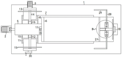
Fig. 1 is a top view of a straight edge machine for wood processing according to the present invention, which has a stable cutting and is convenient to adjust;
FIG. 2 is a partial perspective view of a straight edge machine for woodworking proposed by the invention with stable cutting and convenient adjustment;
fig. 3 is a working representation of a straight edge machine for wood working according to the present invention, which has stable cutting and convenient adjustment;
FIG. 4 is a side view of a straight edge machine for wood working according to the present invention with stable cutting and easy adjustment;
FIG. 5 is an enlarged view of a portion of FIG. 4 at A;
fig. 6 is a partially enlarged view of fig. 1 at B.
In the figure: 1 bottom plate, 2 first motors, 3 second motors, 4 electric telescopic rods, 5 gantry supports, 6L-shaped bases, 7 first chutes, 8 first sliders, 9 first reciprocating screw rods, 10 second chutes, 11 second sliders, 12 first bolts, 13L-shaped plates, 14 rotating shafts, 15 cutting blades, 16 telescopic columns, 17 third chutes, 18 third sliders, 19 second reciprocating screw rods, 20 belt pulleys, 21 belts, 22 fourth chutes, 23 fourth sliders, 24 second bolts, 25 gears, 26 rack plates, 27 first pressing plates, 28 connecting plates, 29 second pressing plates and 30 driving plates.
Detailed Description
The technical solutions in the embodiments of the present invention will be clearly and completely described below with reference to the drawings in the embodiments of the present invention, and it is obvious that the described embodiments are only a part of the embodiments of the present invention, and not all of the embodiments.
Referring to fig. 1-6, a straight edge machine for wood processing with stable cutting and convenient adjustment comprises a bottom plate 1, a first motor 2, a second motor 3 and an electric telescopic rod 4, wherein the first motor 2 is fixedly arranged on the side wall of the bottom plate 1, the upper end of the bottom plate 1 is provided with a first sliding mechanism, the tail end of an output shaft of the first motor 2 is fixedly connected with the driving end of the first sliding mechanism, the movable end of the first sliding mechanism is provided with an adjusting mechanism, the movable end of the adjusting mechanism is provided with a cutting mechanism, the second motor 3 is fixedly arranged on the movable end of the adjusting mechanism and is fixedly connected with the driving end of the cutting mechanism, the upper end of the bottom plate 1 is fixedly connected with a gantry support 5, the upper end of the gantry support 5 is provided with a second sliding mechanism, the same transmission mechanism is arranged between the driving end of the second sliding mechanism and the output shaft of the first motor 2, the movable end of the second sliding mechanism is fixedly connected with an L-shaped base 6, the upper end of the L-shaped base 6 is provided with a pressing mechanism, the electric telescopic rod 4 is fixedly installed at the upper end of the horizontal part of the L-shaped base 6, the tail end of the output shaft of the electric telescopic rod 4 is fixedly connected with the pressing mechanism, and it should be noted that the upper end of the horizontal part of the L-shaped base 6 is smooth.
First slide mechanism is including setting up in the first spout 7 of bottom plate 1 upper end, be equipped with the first slider 8 of assorted with it in the first spout 7, adjustment mechanism sets up in the upper end of first slider 8, it is connected with first reciprocal lead screw 9 to rotate on the one end inner wall of first spout 7, the one end of first reciprocal lead screw 9 is rotated the one end lateral wall that runs through first spout 7 and is set up and with the terminal fixed connection of output shaft of first motor 2, the first reciprocal lead screw 9 screw thread that is located first spout 7 runs through first slider 8 setting, the setting of first slide mechanism, be convenient for adjustment mechanism and cutting mechanism remove, it needs to explain, as shown in fig. 4, the upper end of first slider 8 extends to first spout 7 outsidely, second spout 10 sets up in the part that first slider 8 extends to outside first spout 7.
Adjustment mechanism is including setting up in the second spout 10 of 8 upper ends of first slider, be equipped with two assorted second sliders 11 with it in the second spout 10, it is connected with first bolt 12 to rotate on the one end inner wall of second spout 10, the one end of first bolt 12 is rotated the one end lateral wall setting that runs through second spout 10, the 12 screw threads of first bolt that are located second spout 10 run through two second slider 11 settings, the equal fixedly connected with L template 13 in upper end of two second sliders 11, 3 fixed mounting of second motor are on the lateral wall of one of them L template 13 vertical portion, cutting mechanism and the equal rotation of the inner wall of two L template 13 vertical portions are connected, adjustment mechanism's setting, the staff of being convenient for adjusts the width of wood cutting.
Cutting mechanism includes that two are equallyd divide and do not rotate the pivot 14 of connecting on two vertical partial inner walls of L template 13, equal coaxial fixedly connected with cutting blade 15 on two pivot 14, the same flexible post 16 of root of the same one end fixedly connected with that two pivot 14 are relative, the one end of one of them pivot 14 is rotated and is run through the lateral wall setting that corresponds the vertical portion of L template 13 and with the terminal fixed connection of output shaft of second motor 3, cutting mechanism's setting, the cutting action to timber has been realized, it is required to explain, two flexible sections on the flexible post 16 only can the relative movement stretch out and draw back, relative rotation can not take place, this is prior art, no longer give unnecessary details here.
The second sliding mechanism comprises a third sliding groove 17 arranged at the upper end of the gantry support 5, a third sliding block 18 matched with the third sliding groove is arranged in the third sliding groove 17, a second reciprocating screw rod 19 is rotatably connected to the inner wall of one end of the third sliding groove 17, one end of the second reciprocating screw rod 19 is rotatably arranged on the side wall of one end penetrating through the third sliding groove 17 and fixedly connected with the transmission mechanism, the second reciprocating screw rod 19 in the third sliding groove 17 is arranged through the third sliding block 18 in a threaded manner, the lower end of the L-shaped base 6 is fixedly connected with the upper end of the third sliding block 18, the second sliding mechanism is arranged, the L-shaped base 6 is convenient to move, the transmission mechanism comprises two belt pulleys 20 respectively coaxially and fixedly connected with the second reciprocating screw rod 19 and an output shaft of the first motor 2, the two belt pulleys 20 are in transmission connection through a same belt 21, and the transmission mechanism is arranged, and the utilization rate of the device to the first motor 2 is improved.
The compressing mechanism comprises a fourth sliding chute 22 arranged at the upper end of the horizontal part of the L-shaped base 6, two fourth sliding blocks 23 matched with the fourth sliding chute 22 are arranged in the fourth sliding chute 22, a same second bolt 24 is rotatably connected between the opposite inner walls at the two ends of the fourth sliding chute 22, a second bolt 24 penetrates through the two fourth sliding blocks 23 in a threaded manner, a gear 25 is coaxially and fixedly connected onto the second bolt 24 between the two fourth sliding blocks 23, a rack plate 26 is meshed onto the gear 25, a first pressing plate 27 is fixedly connected onto the side wall of one end of the rack plate 26, the tail end of the output shaft of the electric telescopic rod 4 is fixedly connected with the side wall of one end of the first pressing plate 27, connecting plates 28 are fixedly connected onto the upper ends of the two fourth sliding blocks 23, one ends of the two connecting plates 28 far away from the corresponding fourth sliding blocks 23 are fixedly connected with second pressing plates 29, and the compressing mechanism is arranged, so that the stability of wood cutting is effectively improved, it should be noted that the cutting blade 15 does not collide with the second pressing plate 29 and the connecting plate 28, and it should be noted that neither of the two fourth sliding blocks 23 collides with the gear 25, the driving plate 30 is fixedly connected to one end of the first bolt 12 located outside the second sliding chute 10, and the driving plate 30 is disposed to facilitate the worker to drive the first bolt 12.
It should be noted that, as shown in fig. 6, two sections of second threads (not shown in the figure) are provided on the second bolt 24, and the two fourth sliding blocks 23 are respectively provided on the two sections of second threads, so that when the second bolt 24 rotates, the two fourth sliding blocks 23 move towards the opposite end or the opposite end.
In the process of reciprocating the electric telescopic rod 4, the gear 25 and the rack plate 26 are always engaged with each other.
It should be noted that two sections of first threads (not shown in the figures) are disposed on the first bolt 12, and the two second sliding blocks 11 are disposed on the two sections of second threads, respectively, so that when the first bolt 12 rotates, the two second sliding blocks 11 move towards the opposite end or the opposite end.
It should be noted that the device does not collide during operation.
In the invention, when wood needs to be bilaterally cut, as shown in fig. 3, a worker places two sides of the wood on the upper end of the horizontal part of the L-shaped base 6 in a balanced manner, so that the two ends of the wood are respectively the same as the distance between the cutting blades 15 at the two ends, and one end of the wood is in contact with the vertical end of the L-shaped base 6, then the electric telescopic rod 4 is started to work, the electric telescopic rod 4 drives the first pressing plate 27 to move towards one end close to the wood, the first pressing plate 27 drives the rack plate 26 to synchronously move towards one end close to the wood, the first rack plate 26 moves to rotate the gear 25, the gear 25 rotates to drive the second bolt 24 to rotate, the second bolt 24 rotates to enable the two fourth sliding blocks 23 to move towards the opposite end under the limiting effect of the fourth sliding groove 22, and further enable the two second pressing plates 29 to move towards the opposite end, when the first pressing plate 27 is in contact with and compresses one end of the wood, the two second pressing plates 29 just respectively press the other two sides of the wood, and it should be noted that, when the worker places the wood unevenly, the relative movement of the two second pressing plates 29 can also adjust the position of the wood, so that the wood is located at the equilibrium position on the L-shaped base 6, after the wood is pressed, the first motor 2 and the second motor 3 are started to work synchronously, the second motor 3 rotates to drive the rotating shaft 14 fixedly connected with the second motor to rotate, one rotating shaft 14 rotates to drive the other rotating shaft 14 to rotate synchronously, so that the two cutting blades 15 rotate, the first motor 2 rotates to drive the first reciprocating screw rod 9 to rotate, the first reciprocating screw rod 9 rotates to drive the first sliding block 8 to move horizontally towards the direction of the wood under the limiting effect of the first sliding groove 7, so that the two cutting blades 15 both move horizontally towards the direction of the wood, the first motor 2 rotates to drive the transmission mechanism to transmit, the transmission mechanism drives the second reciprocating screw rod 19 to rotate, the second reciprocating screw rod 19 rotates to enable the third sliding block 18 to horizontally move towards the cutting blade 15 under the limiting effect of the third sliding groove 17, and further, wood horizontally moves towards the cutting blade 15, therefore, the cutting blade 15 and the wood move in opposite directions, and further, the cutting efficiency of the cutting blade 15 is accelerated, after the cutting is finished, the third sliding block 18 and the first sliding block 8 move to the limit position and start to horizontally move towards opposite directions until the cutting blade is reset to the original state, after the resetting, the first motor 2 and the second motor 3 stop running, at the moment, the electric telescopic rod 4 drives the first pressing plate 27 to move towards the direction far away from the wood, further, the gear 25 reversely rotates relative to the previous direction, so that the two second pressing plates 29 also move towards the direction far away from the wood, and finally, the cut wood edge drops, the staff can get the piece, get a back, the staff can continue to repeat above-mentioned step, cut new timber, when the staff need adjust the width of cutting, the staff can manually rotate driving-disc 30, and then make first bolt 12 rotate, first bolt 12 rotates and makes two second sliders 11 under the limiting displacement of second spout 10, to relative or opposite direction horizontal migration, and then make two L templates 13 to relative or opposite direction horizontal migration, thereby make two cutting blade 15 to relative or opposite direction horizontal migration, and then realized the regulating action to timber side cut width.
The above description is only for the preferred embodiment of the present invention, but the scope of the present invention is not limited thereto, and any person skilled in the art should be considered to be within the technical scope of the present invention, and the technical solutions and the inventive concepts thereof according to the present invention should be equivalent or changed within the scope of the present invention.
Claims (1)
1. The utility model provides a cutting is stable and convenient straight flange machine for wood working who adjusts, includes bottom plate (1), first motor (2), second motor (3) and electric telescopic handle (4), its characterized in that, first motor (2) fixed mounting is on the lateral wall of bottom plate (1), the upper end of bottom plate (1) is equipped with first slide mechanism, the output shaft end of first motor (2) and first slide mechanism's drive end fixed connection, be equipped with adjustment mechanism on first slide mechanism's the expansion end, be equipped with cutting mechanism on adjustment mechanism's the expansion end, second motor (3) fixed mounting on adjustment mechanism's the expansion end and with cutting mechanism's drive end fixed connection, the upper end fixedly connected with gantry support (5) of bottom plate (1), the upper end of gantry support (5) is equipped with second slide mechanism, be equipped with same transmission drive between second slide mechanism's drive end and the output shaft of first motor (2) The mechanism is characterized in that an L-shaped base (6) is fixedly connected to the movable end of the second sliding mechanism, a pressing mechanism is arranged at the upper end of the L-shaped base (6), the electric telescopic rod (4) is fixedly installed at the upper end of the horizontal part of the L-shaped base (6), and the tail end of an output shaft of the electric telescopic rod (4) is fixedly connected with the pressing mechanism;
the first sliding mechanism comprises a first sliding chute (7) arranged at the upper end of the bottom plate (1), a first sliding block (8) matched with the first sliding chute (7) is arranged in the first sliding chute (7), the adjusting mechanism is arranged at the upper end of the first sliding block (8), a first reciprocating screw rod (9) is rotatably connected to the inner wall of one end of the first sliding chute (7), one end of the first reciprocating screw rod (9) is rotatably arranged to penetrate through the side wall of one end of the first sliding chute (7) and is fixedly connected with the tail end of an output shaft of the first motor (2), and the first reciprocating screw rod (9) positioned in the first sliding chute (7) is arranged to penetrate through the first sliding block (8) in a threaded manner;
the adjusting mechanism comprises a second sliding groove (10) arranged at the upper end of a first sliding block (8), two second sliding blocks (11) matched with the second sliding groove are arranged in the second sliding groove (10), a first bolt (12) is rotatably connected to the inner wall of one end of the second sliding groove (10), one end of the first bolt (12) is rotatably arranged to penetrate through the side wall of one end of the second sliding groove (10), the first bolt (12) positioned in the second sliding groove (10) is arranged to penetrate through the two second sliding blocks (11) in a threaded manner, the upper ends of the two second sliding blocks (11) are fixedly connected with L-shaped plates (13), a second motor (3) is fixedly arranged on the side wall of the vertical part of one L-shaped plate (13), and the cutting mechanism is rotatably connected with the inner walls of the vertical parts of the two L-shaped plates (13);
the cutting mechanism comprises two rotating shafts (14) which are respectively and rotatably connected to the inner walls of the vertical parts of the two L-shaped plates (13), the two rotating shafts (14) are coaxially and fixedly connected with cutting blades (15), one ends, opposite to the two rotating shafts (14), of the two rotating shafts (14) are fixedly connected with the same telescopic column (16), and one end of one rotating shaft (14) rotatably penetrates through the side wall of the corresponding vertical part of the L-shaped plate (13) and is fixedly connected with the tail end of an output shaft of the second motor (3);
the second sliding mechanism comprises a third sliding chute (17) arranged at the upper end of the gantry support (5), a third sliding block (18) matched with the third sliding chute is arranged in the third sliding chute (17), a second reciprocating screw rod (19) is rotatably connected to the inner wall of one end of the third sliding chute (17), one end of the second reciprocating screw rod (19) rotatably penetrates through the side wall of one end of the third sliding chute (17) and is fixedly connected with the transmission mechanism, a second reciprocating screw rod (19) positioned in the third sliding chute (17) is arranged in a threaded manner to penetrate through the third sliding block (18), and the lower end of the L-shaped base (6) is fixedly connected with the upper end of the third sliding block (18);
the transmission mechanism comprises two belt pulleys (20) which are coaxially and fixedly connected with the second reciprocating screw rod (19) and the output shaft of the first motor (2), and the two belt pulleys (20) are in transmission connection through the same belt (21);
the pressing mechanism comprises a fourth sliding groove (22) arranged at the upper end of the horizontal part of the L-shaped base (6), two fourth sliding blocks (23) matched with the fourth sliding groove are arranged in the fourth sliding groove (22), a same second bolt (24) is rotatably connected between the two opposite inner walls of the two ends of the fourth sliding groove (22), the second bolt (24) penetrates through the two fourth sliding blocks (23) in a threaded manner, a gear (25) is coaxially and fixedly connected onto the second bolt (24) between the two fourth sliding blocks (23), a rack plate (26) is meshed onto the gear (25), a first pressing plate (27) is fixedly connected onto one side wall of one end of the rack plate (26), the tail end of an output shaft of the electric telescopic rod (4) is fixedly connected with one side wall of the first pressing plate (27), and a connecting plate (28) is fixedly connected onto the upper ends of the two fourth sliding blocks (23), one ends of the two connecting plates (28) far away from the corresponding fourth sliding blocks (23) are fixedly connected with second pressing plates (29);
one end of the first bolt (12) positioned outside the second sliding groove (10) is fixedly connected with a driving disc (30).
Priority Applications (2)
| Application Number | Priority Date | Filing Date | Title |
|---|---|---|---|
| CN202210007938.0A CN114290449A (en) | 2020-05-31 | 2020-05-31 | Straight edge machine for wood processing and use method thereof |
| CN202010481035.7A CN111571731B (en) | 2020-05-31 | 2020-05-31 | Straight edge machine for wood processing with stable cutting and convenient adjustment |
Applications Claiming Priority (1)
| Application Number | Priority Date | Filing Date | Title |
|---|---|---|---|
| CN202010481035.7A CN111571731B (en) | 2020-05-31 | 2020-05-31 | Straight edge machine for wood processing with stable cutting and convenient adjustment |
Related Child Applications (1)
| Application Number | Title | Priority Date | Filing Date |
|---|---|---|---|
| CN202210007938.0A Division CN114290449A (en) | 2020-05-31 | 2020-05-31 | Straight edge machine for wood processing and use method thereof |
Publications (2)
| Publication Number | Publication Date |
|---|---|
| CN111571731A CN111571731A (en) | 2020-08-25 |
| CN111571731B true CN111571731B (en) | 2022-06-24 |
Family
ID=72118189
Family Applications (2)
| Application Number | Title | Priority Date | Filing Date |
|---|---|---|---|
| CN202010481035.7A Active CN111571731B (en) | 2020-05-31 | 2020-05-31 | Straight edge machine for wood processing with stable cutting and convenient adjustment |
| CN202210007938.0A Pending CN114290449A (en) | 2020-05-31 | 2020-05-31 | Straight edge machine for wood processing and use method thereof |
Family Applications After (1)
| Application Number | Title | Priority Date | Filing Date |
|---|---|---|---|
| CN202210007938.0A Pending CN114290449A (en) | 2020-05-31 | 2020-05-31 | Straight edge machine for wood processing and use method thereof |
Country Status (1)
| Country | Link |
|---|---|
| CN (2) | CN111571731B (en) |
Families Citing this family (1)
| Publication number | Priority date | Publication date | Assignee | Title |
|---|---|---|---|---|
| CN114872147B (en) * | 2022-04-20 | 2023-04-11 | 安徽宏志建材科技有限公司 | Press-fit equipment for sandwich panel processing |
Family Cites Families (14)
| Publication number | Priority date | Publication date | Assignee | Title |
|---|---|---|---|---|
| CA2686670C (en) * | 2002-01-17 | 2012-09-25 | Iggesund Tools Ab | Multi-application wood working knife and clamping assembly |
| SE519701C2 (en) * | 2002-06-19 | 2003-04-01 | Iggesund Tools Ab | Rotary cutter block for wood chipping machine, has cutting edge bordered by timber and chip guide surfaces with given angular configurations |
| CN203254492U (en) * | 2013-03-27 | 2013-10-30 | 王九天 | Misplaced horizontally-arranged type multiple blade saw sawing machine |
| CN105798994A (en) * | 2016-05-10 | 2016-07-27 | 安徽坤昌家具有限公司 | Locating device for wood processing |
| CN207128009U (en) * | 2017-06-15 | 2018-03-23 | 重庆梁山群星装饰建材有限公司 | A kind of timber fixing device of timber automatic charging cutting machine |
| CN107839021A (en) * | 2017-12-10 | 2018-03-27 | 四川冠腾科技有限公司 | A kind of adjustable plank cutting processing device |
| CN207983548U (en) * | 2018-03-16 | 2018-10-19 | 桃江县万顺木业有限公司 | A kind of wood material cutting machine |
| CN108943150A (en) * | 2018-08-14 | 2018-12-07 | 东莞理工学院 | A kind of smart-cut platform |
| CN209615762U (en) * | 2018-10-27 | 2019-11-12 | 中建八局第二建设有限公司 | A kind of cutter device of plank |
| CN109366634A (en) * | 2018-12-04 | 2019-02-22 | 涟水桂前木材加工厂 | A kind of cutting is stable and facilitates the timber processing straight flange machine of adjusting |
| CN209551912U (en) * | 2019-01-04 | 2019-10-29 | 济宁三联木业有限公司 | A kind of production fibre board use Ban Pei edging saw |
| CN210551821U (en) * | 2019-03-29 | 2020-05-19 | 信阳百德实业有限公司 | Novel double-end saw |
| CN210024746U (en) * | 2019-05-08 | 2020-02-07 | 山东晨特木业有限公司 | Wood environment-friendly double-side inclined grinding machine |
| CN110893635A (en) * | 2019-12-17 | 2020-03-20 | 重庆市豪迈家具有限公司 | Timber door plant cutting device |
-
2020
- 2020-05-31 CN CN202010481035.7A patent/CN111571731B/en active Active
- 2020-05-31 CN CN202210007938.0A patent/CN114290449A/en active Pending
Also Published As
| Publication number | Publication date |
|---|---|
| CN111571731A (en) | 2020-08-25 |
| CN114290449A (en) | 2022-04-08 |
Similar Documents
| Publication | Publication Date | Title |
|---|---|---|
| CN111571731B (en) | Straight edge machine for wood processing with stable cutting and convenient adjustment | |
| CN108943355A (en) | A kind of new precast panel cutting bed | |
| CN107950626A (en) | Meat process equipment in blocks | |
| CN209633203U (en) | A kind of equidistant cutter device of timber | |
| CN208601598U (en) | For sheet fabrication molding cutter structure | |
| CN208247827U (en) | A kind of multilayer office appliance laying rack | |
| CN216859925U (en) | A cutting device for rock wool board preparation | |
| CN210334536U (en) | Sheet metal part machining device | |
| CN210551579U (en) | Splitting machine with adjustable splitting interval | |
| CN114619496A (en) | Cutting equipment capable of self-adapting to fruit and vegetable slitting position and using method thereof | |
| CN113756083A (en) | Shearing equipment for clothing production | |
| CN208513741U (en) | A kind of roof of the vehicle reduction cutter device | |
| CN209319873U (en) | A kind of automatic positioning wall patch bead cutter | |
| CN208179777U (en) | A kind of efficient machine and wood cutting | |
| CN212554115U (en) | Positioning structure of cutting equipment for circuit board production | |
| CN218857487U (en) | Automatic pressure extension device for producing silica gel belt | |
| CN216682374U (en) | Metal curtain wall sandwich panel cutting device | |
| CN219854743U (en) | Slicer of adjustable section thickness | |
| CN218928075U (en) | Automatic change high-efficient accurate cut-to-size saw | |
| CN216328869U (en) | Portable saw blade that conveniently adjusts and use | |
| CN219027628U (en) | Safe transverse cutting machine | |
| CN220362617U (en) | Rubber cutting machine is used in V-belt production | |
| CN216178326U (en) | Notch polishing device for processing door and window aluminum profiles | |
| CN220503356U (en) | Loom with tailor function | |
| CN215549392U (en) | Woodwork cutting device |
Legal Events
| Date | Code | Title | Description |
|---|---|---|---|
| PB01 | Publication | ||
| PB01 | Publication | ||
| SE01 | Entry into force of request for substantive examination | ||
| SE01 | Entry into force of request for substantive examination | ||
| TA01 | Transfer of patent application right | ||
| TA01 | Transfer of patent application right |
Effective date of registration: 20220601 Address after: 528308 Beihai Industrial Zone, Yiheng Road, changjiao City, Lunjiao, Shunde District, Foshan City, Guangdong Province Applicant after: GUANGDONG SHUNDE YONGQIANG FUTAI INTELLIGENT WOODWORKING MACHINERY Co.,Ltd. Address before: Room 202, 002 and 105, unit 03, building 025, sunshine garden, Donggang District, Rizhao City, Shandong Province 276800 Applicant before: Rizhao Yachuang Electronic Technology Co.,Ltd. |
|
| GR01 | Patent grant | ||
| GR01 | Patent grant |