CN111570272A - Sand screening device for land development of industrial gathering area - Google Patents
Sand screening device for land development of industrial gathering area Download PDFInfo
- Publication number
- CN111570272A CN111570272A CN202010495362.8A CN202010495362A CN111570272A CN 111570272 A CN111570272 A CN 111570272A CN 202010495362 A CN202010495362 A CN 202010495362A CN 111570272 A CN111570272 A CN 111570272A
- Authority
- CN
- China
- Prior art keywords
- plate
- welded
- screening device
- box body
- sand
- Prior art date
- Legal status (The legal status is an assumption and is not a legal conclusion. Google has not performed a legal analysis and makes no representation as to the accuracy of the status listed.)
- Pending
Links
Images


Classifications
-
- B—PERFORMING OPERATIONS; TRANSPORTING
- B07—SEPARATING SOLIDS FROM SOLIDS; SORTING
- B07B—SEPARATING SOLIDS FROM SOLIDS BY SIEVING, SCREENING, SIFTING OR BY USING GAS CURRENTS; SEPARATING BY OTHER DRY METHODS APPLICABLE TO BULK MATERIAL, e.g. LOOSE ARTICLES FIT TO BE HANDLED LIKE BULK MATERIAL
- B07B1/00—Sieving, screening, sifting, or sorting solid materials using networks, gratings, grids, or the like
- B07B1/28—Moving screens not otherwise provided for, e.g. swinging, reciprocating, rocking, tilting or wobbling screens
-
- B—PERFORMING OPERATIONS; TRANSPORTING
- B07—SEPARATING SOLIDS FROM SOLIDS; SORTING
- B07B—SEPARATING SOLIDS FROM SOLIDS BY SIEVING, SCREENING, SIFTING OR BY USING GAS CURRENTS; SEPARATING BY OTHER DRY METHODS APPLICABLE TO BULK MATERIAL, e.g. LOOSE ARTICLES FIT TO BE HANDLED LIKE BULK MATERIAL
- B07B1/00—Sieving, screening, sifting, or sorting solid materials using networks, gratings, grids, or the like
- B07B1/42—Drive mechanisms, regulating or controlling devices, or balancing devices, specially adapted for screens
-
- B—PERFORMING OPERATIONS; TRANSPORTING
- B07—SEPARATING SOLIDS FROM SOLIDS; SORTING
- B07B—SEPARATING SOLIDS FROM SOLIDS BY SIEVING, SCREENING, SIFTING OR BY USING GAS CURRENTS; SEPARATING BY OTHER DRY METHODS APPLICABLE TO BULK MATERIAL, e.g. LOOSE ARTICLES FIT TO BE HANDLED LIKE BULK MATERIAL
- B07B1/00—Sieving, screening, sifting, or sorting solid materials using networks, gratings, grids, or the like
- B07B1/46—Constructional details of screens in general; Cleaning or heating of screens
Abstract
The invention belongs to the field of industrial gathering civil engineering equipment, and particularly relates to a sand screening device for land development of an industrial gathering area, aiming at the problems that the existing sand screening device is low in efficiency and inconvenient to clean sand below a screen plate. The sand screening device effectively improves screening efficiency, is convenient to clean sand below the screen plate, and is simple to operate.
Description
Technical Field
The invention relates to the technical field of industrial gathering civil engineering equipment, in particular to a sand screening device for land development of an industrial gathering area.
Background
In the industrial gathering area production: civil engineering is a general name of scientific technology for building various engineering facilities, common building materials such as sand and cement are often required to be used in the implementation process of civil engineering, and the quality of the materials directly influences the quality of buildings.
The current sand screening device is low in efficiency and inconvenient to clean sand below the screen plate.
Disclosure of Invention
The invention aims to solve the defects that the efficiency of a sand screening device is low and sand below a screen plate is inconvenient to clean in the prior art, and provides the sand screening device for land development of an industrial gathering area.
In order to achieve the purpose, the invention adopts the following technical scheme:
a sand screening device for land development of an industrial gathering area comprises a processing box with openings at the top and the bottom, sliding holes are formed in two sides of the processing box, sliding plates are slidably mounted in the sliding holes, one side, close to each other, of each sliding plate is fixedly connected with the same box body, openings are formed in the top and the bottom of each box body, two first springs are welded on two sides of each box body, one ends, far away from each other, of the two first springs on the same horizontal axis are respectively welded on the inner walls of two sides of the processing box, rotating holes are formed in the box body, a rotating shaft is rotatably mounted in each rotating hole, two rotating plates are fixedly sleeved on the outer side of each rotating shaft, one side of each rotating plate is fixedly connected with the same sealing plate, a mounting hole is formed in the top of each sealing plate, a sieve plate is fixedly connected in each mounting hole, a pulling plate is welded on one side of the traction plate, a limiting plate is welded on one side of the pulling plate, a limiting groove is formed in one side of the box body, the limiting plate and the limiting groove are clamped, two second springs are welded on one side of the pulling plate and welded with one end of the box body, a mounting plate is fixedly connected to one side of the treatment box, a driving motor is fixedly connected to the top of the mounting plate, a driving shaft is welded on an output shaft of the driving motor, a side plate is welded on one side of the treatment box, a first hole is formed in the top of the side plate, a first bearing is fixedly connected in the first hole and fixedly mounted on an inner ring of the first bearing, a cam is fixedly sleeved on the outer side of the driving shaft and contacted with a sliding plate, a first conical gear is welded at the bottom end of the driving shaft, supporting plates are welded on two sides of the bottom of, the inner rings of the two second bearings are fixedly connected with the same cross shaft, a plurality of sand pushing plates are welded on the outer side of the cross shaft, a second bevel gear is welded at one end of the cross shaft, the first bevel gear is meshed with the second bevel gear, and the transmission ratio of the first bevel gear to the second bevel gear is 10: 1.
preferably, the risers all welded in the top both sides of handling the case, and the diaphragm is all welded at the one side top that two risers are close to each other, and the same feeder hopper of one side fixedly connected with that two diaphragms are close to each other, the feeding of being convenient for.
Preferably, the top of the mounting plate is provided with a through hole, and the bottom end of the driving shaft penetrates through the through hole.
Preferably, a first handle is welded to one side of the pulling plate.
Preferably, a second handle is welded to the bottom of the sealing plate.
Preferably, the sealing plate is in sealing contact with the bottom opening of the box body to seal the bottom opening of the box body.
Preferably, the number of the sand pushing plates is two, and sand below the sieve plate is cleaned out.
Preferably, the box body is positioned between the two rotating plates.
According to the sand screening device for the land development of the industrial gathering area, when sand screening treatment is needed, sand is added into the box body through the feed hopper, then the driving motor is started, the driving shaft drives the cam to rotate, the cam extrudes one sliding plate to drive the sliding plate to move, the sliding plate drives the box body to move, the box body respectively extrudes and stretches the first springs on the two sides, and the box body can transversely move back and forth under the continuous rotation of the cam, so that the sand screening is realized;
the drive shaft drives first conical gear and rotates, second conical gear drives the cross axle and rotates, the cross axle drives and pushes away the sand board and rotates, it promotes the sand to push away the sand board, the sand under will screening pushes away, the screening is accomplished the back, the first in command of pulling, the arm-tie drives the traction plate and removes, the arm-tie stretches the second spring, the arm-tie drives the limiting plate and removes, make the limiting plate move out the limiting groove, then the second in command of pulling, the closing plate drives the sieve and rotates, the closing plate drives the runner and rotates, the runner drives the pivot and rotates, debris after will filtering take out.
The sand screening device effectively improves screening efficiency, is convenient to clean sand below the screen plate, and is simple to operate.
Drawings
FIG. 1 is a schematic structural view of a sand screening device for use in land development in an industrial gathering area in accordance with the present invention;
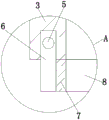
FIG. 2 is a schematic view of part A of a sand screening device for use in land development in an industrial agglomeration area according to the present invention;
FIG. 3 is a schematic view of part B of a sand screening device for use in land development in an industrial agglomeration area according to the present invention;
FIG. 4 is a schematic structural view of portion C of a sand screening device for use in land development in an industrial agglomeration area in accordance with the present invention;
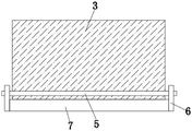
fig. 5 is a side view schematically showing the structure of a connection part of a rotary shaft and a rotary plate of a sand sieving device for land development in an industrial concentration area according to the present invention.
In the figure: 1. a treatment tank; 2. a slide plate; 3. a box body; 4. a first spring; 5. a rotating shaft; 6. rotating the plate; 7. a sealing plate; 8. a sieve plate; 9. a traction plate; 10. pulling a plate; 11. a limiting plate; 12. a second spring; 13. mounting a plate; 14. a drive motor; 15. a side plate; 16. a drive shaft; 17. a first bearing; 18. a cam; 19. a first bevel gear; 20. a support plate; 21. a second bearing; 22. a horizontal axis; 23. pushing a sand plate; 24. a second bevel gear; 25. a vertical plate; 26. a transverse plate; 27. a feed hopper.
Detailed Description
The technical solutions in the embodiments of the present invention will be clearly and completely described below with reference to the drawings in the embodiments of the present invention, and it is obvious that the described embodiments are only a part of the embodiments of the present invention, and not all of the embodiments.
Referring to fig. 1-5, a sand sieving device for land development of an industrial gathering area comprises a processing box 1 with openings at the top and the bottom, sliding holes are arranged at both sides of the processing box 1, sliding plates 2 are slidably mounted in the sliding holes, one side of each of the two sliding plates 2 close to each other is fixedly connected with a box body 3, openings are arranged at the top and the bottom of the box body 3, two first springs 4 are welded at both sides of the box body 3, the ends of the two first springs 4 which are positioned on the same horizontal axis and far away from each other are respectively welded on the inner walls at both sides of the processing box 1, rotating holes are arranged on the box body 3, a rotating shaft 5 is rotatably mounted in the rotating holes, two rotating plates 6 are fixedly sleeved at the outer side of the rotating shaft 5, one side of the two rotating plates 6 is fixedly connected with a same sealing plate 7, mounting holes are arranged, one side of the box body 3 is provided with a traction groove, a traction plate 9 is arranged in the traction groove in a sliding mode, one side of the traction plate 9 is welded with a pulling plate 10, one side of the pulling plate 10 is welded with a limiting plate 11, one side of the box body 3 is provided with a limiting groove, the limiting plate 11 is clamped with the limiting groove, one side of the pulling plate 10 is welded with two second springs 12, the second springs 12 are welded with one end of the box body 3, one side of the treatment box 1 is fixedly connected with a mounting plate 13, the top of the mounting plate 13 is fixedly connected with a driving motor 14, an output shaft of the driving motor 14 is welded with a driving shaft 16, one side of the treatment box 1 is welded with a side plate 15, the top of the side plate 15 is provided with a first hole, a first bearing 17 is fixedly connected in the first hole, the driving shaft 16 is fixedly arranged on the inner ring of the first bearing 17, a cam 18 is fixedly sleeved on, the bottom both sides of handling case 1 all have welded backup pad 20, the second hole has been seted up on backup pad 20, the downthehole fixedly connected with second bearing 21 of second, the same cross axle 22 of the inner circle fixedly connected with of two second bearings 21, the outside welding of cross axle 22 has a plurality of sand pushing plates 23, the one end welding of cross axle 22 has second conical gear 24, first conical gear 19 meshes with second conical gear 24 mutually, first conical gear 19 is 10 with second conical gear 24's drive ratio: 1.
in the invention, the vertical plates 25 are welded on both sides of the top of the treatment box 1, the transverse plates 26 are welded on the top of the side where the two vertical plates 25 are close to each other, and the same feed hopper 27 is fixedly connected on the side where the two transverse plates 26 are close to each other, so that feeding is facilitated.
In the present invention, the top of the mounting plate 13 is provided with a through hole, and the bottom end of the driving shaft 16 penetrates through the through hole.
In the invention, a first handle is welded on one side of the pulling plate 10.
In the present invention, the second handle is welded to the bottom of the sealing plate 7.
In the present invention, the sealing plate 7 is in sealing contact with the bottom opening of the case 3 to seal the bottom opening of the case 3.
In the invention, the number of the sand pushing plates 23 is two, and sand below the sieve plate 8 is cleaned out.
In the present invention, the case 3 is positioned between the two rotating plates 6.
In the invention, when sand screening treatment is required, sand is added into a box body 3 through a feed hopper 27, then a driving motor 14 is started, the driving motor 14 is controlled through a control switch, the driving motor 14 is powered by mains supply, an output shaft of the driving motor 14 drives a driving shaft 16 to rotate, the driving shaft 16 drives a cam 18 to rotate, the cam 18 extrudes a sliding plate 2 to drive the sliding plate 2 to move, the sliding plate 2 drives the box body 3 to move, the box body 3 respectively extrudes and stretches first springs 4 at two sides, the box body 3 can transversely move back and forth under the continuous rotation of the cam 18 to screen the sand, the driving shaft 16 drives a first bevel gear 19 to rotate, the first bevel gear 19 drives a second bevel gear 24 to rotate, the second bevel gear 24 drives a transverse shaft 22 to rotate, and the transverse shaft 22 drives a sand pushing plate 23 to rotate, push away the sand board 23 and promote the sand, the sand under the screening is pushed out, the screening is accomplished the back, the pulling first in command, the first in command drives arm-tie 10 and removes, arm-tie 10 drives the traction plate 9 and removes, the arm-tie 10 is stretched second spring 12, arm-tie 10 drives limiting plate 11 and removes, make limiting plate 11 move out the limiting groove, then the pulling second in command, the second in command drives closing plate 7 and rotates, closing plate 7 drives sieve 8 and rotates, closing plate 7 drives and changes board 6 and rotate, it rotates to change board 6 and drive pivot 5, debris after will filtering take out.
While there have been shown and described what are at present considered the fundamental principles and essential features of the invention and its advantages, it will be apparent to those skilled in the art that the invention is not limited to the details of the foregoing exemplary embodiments, but is capable of other specific forms without departing from the spirit or essential characteristics thereof. The present embodiments are therefore to be considered in all respects as illustrative and not restrictive, the scope of the invention being indicated by the appended claims rather than by the foregoing description, and all changes which come within the meaning and range of equivalency of the claims are therefore intended to be embraced therein. Any reference sign in a claim should not be construed as limiting the claim concerned.
Furthermore, it should be understood that although the present description refers to embodiments, not every embodiment may contain only a single embodiment, and such description is for clarity only, and those skilled in the art should integrate the description, and the embodiments may be combined as appropriate to form other embodiments understood by those skilled in the art.
Claims (8)
1. A sand screening device for land development of an industrial gathering area comprises a processing box (1) with openings at the top and the bottom, and is characterized in that sliding holes are formed in the two sides of the processing box (1), sliding plates (2) are arranged in the sliding holes in a sliding mode, one side, close to each other, of each of the two sliding plates (2) is fixedly connected with the same box body (3), openings are formed in the top and the bottom of the box body (3), two first springs (4) are welded to the two sides of the box body (3), one ends, far away from each other, of the two first springs (4) on the same horizontal axis are welded to the inner walls of the two sides of the processing box (1) respectively, rotating holes are formed in the box body (3), a rotating shaft (5) is installed in the rotating holes in a rotating mode, two rotating plates (6) are fixedly sleeved on the outer side of the rotating shaft (5), one side of, the top of the sealing plate (7) is provided with a mounting hole, a sieve plate (8) is fixedly connected in the mounting hole, one side of the box body (3) is provided with a traction groove, a traction plate (9) is arranged in the traction groove in a sliding manner, one side of the traction plate (9) is welded with a pulling plate (10), one side of the pulling plate (10) is welded with a limiting plate (11), one side of the box body (3) is provided with a limiting groove, the limiting plate (11) is clamped with the limiting groove, one side of the pulling plate (10) is welded with two second springs (12), the second springs (12) are welded with one end of the box body (3), one side of the treatment box (1) is fixedly connected with a mounting plate (13), the top of the mounting plate (13) is fixedly connected with a driving motor (14), an output shaft (16) of the driving motor (14) is welded on an output shaft, one side of the treatment box (1, first downthehole fixedly connected with first bearing (17), drive shaft (16) fixed mounting is in the inner circle of first bearing (17), the fixed cover in the outside of drive shaft (16) is equipped with cam (18), cam (18) contact with a slide (2), the bottom welding of drive shaft (16) has first conical gear (19), backup pad (20) have all been welded to the bottom both sides of handling case (1), the second hole has been seted up on backup pad (20), downthehole fixedly connected with second bearing (21) of second, the same cross axle of inner circle fixedly connected with (22) of two second bearings (21), the outside welding of cross axle (22) has a plurality of sand pushing plates (23), the one end welding of cross axle (22) has second conical gear (24), first conical gear (19) mesh with second conical gear (24).
2. The sand screening device for land development of industrial concentration areas according to claim 1, wherein the treatment box (1) has vertical plates (25) welded to both sides of the top, and has transverse plates (26) welded to the top of the side where the vertical plates (25) are close to each other, and the same feed hopper (27) is fixedly connected to the side where the transverse plates (26) are close to each other.
3. A sand screening device for land development of industrial concentration areas according to claim 1, wherein the top of the mounting plate (13) is perforated and the bottom end of the driving shaft (16) is perforated.
4. A sand screening device for land development of industrial concentration areas according to claim 1, characterized in that a first handle is welded to one side of the pulling plate (10).
5. A sand screening device for land development of industrial concentration areas according to claim 1, characterized in that the bottom of the sealing plate (7) is welded with a second handle.
6. A sand screening device for land development of industrial concentration areas according to claim 1, characterized in that the sealing plate (7) is in sealing contact with the bottom opening of the box body (3).
7. A sand screening device for land development of industrial accumulation areas, according to claim 1, characterized in that the number of the sand pushing plates (23) is two.
8. A sand screening device for land development of industrial concentration areas according to claim 1, characterized in that the box (3) is located between two turning plates (6).
Priority Applications (1)
| Application Number | Priority Date | Filing Date | Title |
|---|---|---|---|
| CN202010495362.8A CN111570272A (en) | 2020-06-03 | 2020-06-03 | Sand screening device for land development of industrial gathering area |
Applications Claiming Priority (1)
| Application Number | Priority Date | Filing Date | Title |
|---|---|---|---|
| CN202010495362.8A CN111570272A (en) | 2020-06-03 | 2020-06-03 | Sand screening device for land development of industrial gathering area |
Publications (1)
| Publication Number | Publication Date |
|---|---|
| CN111570272A true CN111570272A (en) | 2020-08-25 |
Family
ID=72122224
Family Applications (1)
| Application Number | Title | Priority Date | Filing Date |
|---|---|---|---|
| CN202010495362.8A Pending CN111570272A (en) | 2020-06-03 | 2020-06-03 | Sand screening device for land development of industrial gathering area |
Country Status (1)
| Country | Link |
|---|---|
| CN (1) | CN111570272A (en) |
Cited By (1)
| Publication number | Priority date | Publication date | Assignee | Title |
|---|---|---|---|---|
| CN112642693A (en) * | 2020-09-21 | 2021-04-13 | 魏火娣 | But multistage screening's gravel and sand sieving mechanism for building |
Citations (7)
| Publication number | Priority date | Publication date | Assignee | Title |
|---|---|---|---|---|
| US20050274654A1 (en) * | 2004-04-15 | 2005-12-15 | Sukovaty Louis G | Method and apparatus for sifting soil |
| CN205496001U (en) * | 2016-03-21 | 2016-08-24 | 张金辉 | Mechatronic two -stage screening sieve device |
| CN208004302U (en) * | 2018-01-22 | 2018-10-26 | 蓝山县金山川粉末冶金有限公司 | A kind of rocking type Sand screen |
| CN208245134U (en) * | 2018-02-05 | 2018-12-18 | 贵州天刺力食品科技有限责任公司 | A kind of Single Roxburgh Rose Fruit sieving-washing machine |
| CN110152984A (en) * | 2019-05-14 | 2019-08-23 | 张伟华 | A kind of agricultural rapeseed screening installation |
| CN210333301U (en) * | 2019-05-27 | 2020-04-17 | 云南锦云建设工程有限公司 | Sand screening machine for constructional engineering |
| CN210497209U (en) * | 2019-09-16 | 2020-05-12 | 王彬 | Sand leakage device for construction of building roads and bridges |
-
2020
- 2020-06-03 CN CN202010495362.8A patent/CN111570272A/en active Pending
Patent Citations (7)
| Publication number | Priority date | Publication date | Assignee | Title |
|---|---|---|---|---|
| US20050274654A1 (en) * | 2004-04-15 | 2005-12-15 | Sukovaty Louis G | Method and apparatus for sifting soil |
| CN205496001U (en) * | 2016-03-21 | 2016-08-24 | 张金辉 | Mechatronic two -stage screening sieve device |
| CN208004302U (en) * | 2018-01-22 | 2018-10-26 | 蓝山县金山川粉末冶金有限公司 | A kind of rocking type Sand screen |
| CN208245134U (en) * | 2018-02-05 | 2018-12-18 | 贵州天刺力食品科技有限责任公司 | A kind of Single Roxburgh Rose Fruit sieving-washing machine |
| CN110152984A (en) * | 2019-05-14 | 2019-08-23 | 张伟华 | A kind of agricultural rapeseed screening installation |
| CN210333301U (en) * | 2019-05-27 | 2020-04-17 | 云南锦云建设工程有限公司 | Sand screening machine for constructional engineering |
| CN210497209U (en) * | 2019-09-16 | 2020-05-12 | 王彬 | Sand leakage device for construction of building roads and bridges |
Cited By (2)
| Publication number | Priority date | Publication date | Assignee | Title |
|---|---|---|---|---|
| CN112642693A (en) * | 2020-09-21 | 2021-04-13 | 魏火娣 | But multistage screening's gravel and sand sieving mechanism for building |
| CN112642693B (en) * | 2020-09-21 | 2022-09-30 | 魏火娣 | But multistage screening's gravel and sand sieving mechanism for building |
Similar Documents
| Publication | Publication Date | Title |
|---|---|---|
| CN108686918B (en) | Automatic soil screening device and system thereof | |
| CN111570272A (en) | Sand screening device for land development of industrial gathering area | |
| CN206519344U (en) | Trommelling machine | |
| CN216459401U (en) | Calcium oxide deironing device | |
| CN207042058U (en) | A kind of environmentally friendly ore cleaning sullage filtration processing equipment | |
| CN214571121U (en) | Effluent treatment plant is used in pesticide production | |
| CN213161853U (en) | Chemical raw material screening device | |
| CN213103211U (en) | Drum screen convenient to clear up screen cloth surface | |
| CN213377686U (en) | Crop seed size screening installation | |
| CN114811263A (en) | Hydraulic pipeline device for hydraulic engineering | |
| CN211678669U (en) | Agricultural seed sieving mechanism | |
| CN106621546A (en) | Environment-friendly ore washing sewage filtering treatment equipment | |
| CN209791942U (en) | Hierarchical sieving mechanism | |
| CN217016424U (en) | Composite biological filter material processing equipment | |
| CN112174380A (en) | Sewage treatment device with replaceable filter screen | |
| CN218642592U (en) | Slag yard waste water grading and recycling device | |
| CN220207594U (en) | Sewage water quality monitoring device based on wireless transmission | |
| CN217888619U (en) | Raw material grading equipment suitable for regeneration processing activated carbon | |
| CN215878693U (en) | Rolling type ash cooling barrel | |
| CN218106894U (en) | Water treatment facilities convenient to change | |
| CN217165198U (en) | Organic fertilizer raw materials sieving mechanism | |
| CN207188202U (en) | A kind of transmission device for cinder screening | |
| CN216653552U (en) | Environmental engineering sewage recovery unit | |
| CN216605989U (en) | Construction waste screening plant convenient to maintain | |
| CN110683668A (en) | Drainage comprehensive utilization system |
Legal Events
| Date | Code | Title | Description |
|---|---|---|---|
| PB01 | Publication | ||
| PB01 | Publication | ||
| SE01 | Entry into force of request for substantive examination | ||
| SE01 | Entry into force of request for substantive examination | ||
| RJ01 | Rejection of invention patent application after publication | ||
| RJ01 | Rejection of invention patent application after publication |
Application publication date: 20200825 |