CN111565663B - Electrosurgical ablation instrument - Google Patents
Electrosurgical ablation instrument Download PDFInfo
- Publication number
- CN111565663B CN111565663B CN201880076180.8A CN201880076180A CN111565663B CN 111565663 B CN111565663 B CN 111565663B CN 201880076180 A CN201880076180 A CN 201880076180A CN 111565663 B CN111565663 B CN 111565663B
- Authority
- CN
- China
- Prior art keywords
- distal
- dielectric material
- microwave
- instrument
- electrosurgical instrument
- Prior art date
- Legal status (The legal status is an assumption and is not a legal conclusion. Google has not performed a legal analysis and makes no representation as to the accuracy of the status listed.)
- Active
Links
- 238000002679 ablation Methods 0.000 title abstract description 12
- 230000005540 biological transmission Effects 0.000 claims abstract description 29
- 238000003780 insertion Methods 0.000 claims abstract description 9
- 230000037431 insertion Effects 0.000 claims abstract description 9
- 239000003989 dielectric material Substances 0.000 claims description 69
- 239000004020 conductor Substances 0.000 claims description 64
- 239000000463 material Substances 0.000 claims description 11
- 238000009558 endoscopic ultrasound Methods 0.000 claims description 9
- 230000005404 monopole Effects 0.000 claims description 8
- 210000000496 pancreas Anatomy 0.000 abstract description 15
- 238000000034 method Methods 0.000 abstract description 12
- 238000007674 radiofrequency ablation Methods 0.000 abstract description 6
- 239000012530 fluid Substances 0.000 description 10
- 239000004696 Poly ether ether ketone Substances 0.000 description 7
- 229920002530 polyetherether ketone Polymers 0.000 description 7
- 239000010949 copper Substances 0.000 description 6
- 239000000523 sample Substances 0.000 description 6
- 206010028980 Neoplasm Diseases 0.000 description 5
- 230000002183 duodenal effect Effects 0.000 description 5
- 230000007246 mechanism Effects 0.000 description 5
- RYGMFSIKBFXOCR-UHFFFAOYSA-N Copper Chemical compound [Cu] RYGMFSIKBFXOCR-UHFFFAOYSA-N 0.000 description 4
- 229910052802 copper Inorganic materials 0.000 description 4
- 238000002604 ultrasonography Methods 0.000 description 4
- 239000000919 ceramic Substances 0.000 description 3
- 206010011732 Cyst Diseases 0.000 description 2
- 229910000831 Steel Inorganic materials 0.000 description 2
- 238000002591 computed tomography Methods 0.000 description 2
- 208000031513 cyst Diseases 0.000 description 2
- 230000000694 effects Effects 0.000 description 2
- 238000005286 illumination Methods 0.000 description 2
- 230000003902 lesion Effects 0.000 description 2
- 238000001465 metallisation Methods 0.000 description 2
- 230000003287 optical effect Effects 0.000 description 2
- 239000004810 polytetrafluoroethylene Substances 0.000 description 2
- 229920001343 polytetrafluoroethylene Polymers 0.000 description 2
- 230000005855 radiation Effects 0.000 description 2
- 229910052709 silver Inorganic materials 0.000 description 2
- 239000004332 silver Substances 0.000 description 2
- 239000010959 steel Substances 0.000 description 2
- 201000011510 cancer Diseases 0.000 description 1
- 239000012809 cooling fluid Substances 0.000 description 1
- 208000012106 cystic neoplasm Diseases 0.000 description 1
- 238000010586 diagram Methods 0.000 description 1
- 210000001198 duodenum Anatomy 0.000 description 1
- 210000004185 liver Anatomy 0.000 description 1
- 210000004072 lung Anatomy 0.000 description 1
- 210000000214 mouth Anatomy 0.000 description 1
- 201000011519 neuroendocrine tumor Diseases 0.000 description 1
- 230000000149 penetrating effect Effects 0.000 description 1
- 230000000704 physical effect Effects 0.000 description 1
- 230000001681 protective effect Effects 0.000 description 1
- 229910001220 stainless steel Inorganic materials 0.000 description 1
- 239000010935 stainless steel Substances 0.000 description 1
- 210000002784 stomach Anatomy 0.000 description 1
- 239000000126 substance Substances 0.000 description 1
- 230000007723 transport mechanism Effects 0.000 description 1
Images


Classifications
-
- A—HUMAN NECESSITIES
- A61—MEDICAL OR VETERINARY SCIENCE; HYGIENE
- A61B—DIAGNOSIS; SURGERY; IDENTIFICATION
- A61B18/00—Surgical instruments, devices or methods for transferring non-mechanical forms of energy to or from the body
- A61B18/18—Surgical instruments, devices or methods for transferring non-mechanical forms of energy to or from the body by applying electromagnetic radiation, e.g. microwaves
- A61B18/1815—Surgical instruments, devices or methods for transferring non-mechanical forms of energy to or from the body by applying electromagnetic radiation, e.g. microwaves using microwaves
-
- A—HUMAN NECESSITIES
- A61—MEDICAL OR VETERINARY SCIENCE; HYGIENE
- A61B—DIAGNOSIS; SURGERY; IDENTIFICATION
- A61B18/00—Surgical instruments, devices or methods for transferring non-mechanical forms of energy to or from the body
- A61B18/18—Surgical instruments, devices or methods for transferring non-mechanical forms of energy to or from the body by applying electromagnetic radiation, e.g. microwaves
-
- A—HUMAN NECESSITIES
- A61—MEDICAL OR VETERINARY SCIENCE; HYGIENE
- A61B—DIAGNOSIS; SURGERY; IDENTIFICATION
- A61B18/00—Surgical instruments, devices or methods for transferring non-mechanical forms of energy to or from the body
- A61B18/04—Surgical instruments, devices or methods for transferring non-mechanical forms of energy to or from the body by heating
- A61B18/12—Surgical instruments, devices or methods for transferring non-mechanical forms of energy to or from the body by heating by passing a current through the tissue to be heated, e.g. high-frequency current
- A61B18/1206—Generators therefor
-
- A—HUMAN NECESSITIES
- A61—MEDICAL OR VETERINARY SCIENCE; HYGIENE
- A61B—DIAGNOSIS; SURGERY; IDENTIFICATION
- A61B18/00—Surgical instruments, devices or methods for transferring non-mechanical forms of energy to or from the body
- A61B18/04—Surgical instruments, devices or methods for transferring non-mechanical forms of energy to or from the body by heating
- A61B18/12—Surgical instruments, devices or methods for transferring non-mechanical forms of energy to or from the body by heating by passing a current through the tissue to be heated, e.g. high-frequency current
- A61B18/14—Probes or electrodes therefor
- A61B18/1492—Probes or electrodes therefor having a flexible, catheter-like structure, e.g. for heart ablation
-
- A—HUMAN NECESSITIES
- A61—MEDICAL OR VETERINARY SCIENCE; HYGIENE
- A61B—DIAGNOSIS; SURGERY; IDENTIFICATION
- A61B8/00—Diagnosis using ultrasonic, sonic or infrasonic waves
- A61B8/12—Diagnosis using ultrasonic, sonic or infrasonic waves in body cavities or body tracts, e.g. by using catheters
-
- A—HUMAN NECESSITIES
- A61—MEDICAL OR VETERINARY SCIENCE; HYGIENE
- A61B—DIAGNOSIS; SURGERY; IDENTIFICATION
- A61B17/00—Surgical instruments, devices or methods, e.g. tourniquets
- A61B17/00234—Surgical instruments, devices or methods, e.g. tourniquets for minimally invasive surgery
- A61B2017/00292—Surgical instruments, devices or methods, e.g. tourniquets for minimally invasive surgery mounted on or guided by flexible, e.g. catheter-like, means
- A61B2017/0034—Surgical instruments, devices or methods, e.g. tourniquets for minimally invasive surgery mounted on or guided by flexible, e.g. catheter-like, means adapted to be inserted through a working channel of an endoscope
-
- A—HUMAN NECESSITIES
- A61—MEDICAL OR VETERINARY SCIENCE; HYGIENE
- A61B—DIAGNOSIS; SURGERY; IDENTIFICATION
- A61B18/00—Surgical instruments, devices or methods for transferring non-mechanical forms of energy to or from the body
- A61B2018/00053—Mechanical features of the instrument of device
- A61B2018/00059—Material properties
- A61B2018/00071—Electrical conductivity
-
- A—HUMAN NECESSITIES
- A61—MEDICAL OR VETERINARY SCIENCE; HYGIENE
- A61B—DIAGNOSIS; SURGERY; IDENTIFICATION
- A61B18/00—Surgical instruments, devices or methods for transferring non-mechanical forms of energy to or from the body
- A61B2018/00315—Surgical instruments, devices or methods for transferring non-mechanical forms of energy to or from the body for treatment of particular body parts
- A61B2018/00482—Digestive system
-
- A—HUMAN NECESSITIES
- A61—MEDICAL OR VETERINARY SCIENCE; HYGIENE
- A61B—DIAGNOSIS; SURGERY; IDENTIFICATION
- A61B18/00—Surgical instruments, devices or methods for transferring non-mechanical forms of energy to or from the body
- A61B2018/00571—Surgical instruments, devices or methods for transferring non-mechanical forms of energy to or from the body for achieving a particular surgical effect
- A61B2018/00577—Ablation
-
- A—HUMAN NECESSITIES
- A61—MEDICAL OR VETERINARY SCIENCE; HYGIENE
- A61B—DIAGNOSIS; SURGERY; IDENTIFICATION
- A61B18/00—Surgical instruments, devices or methods for transferring non-mechanical forms of energy to or from the body
- A61B2018/0091—Handpieces of the surgical instrument or device
-
- A—HUMAN NECESSITIES
- A61—MEDICAL OR VETERINARY SCIENCE; HYGIENE
- A61B—DIAGNOSIS; SURGERY; IDENTIFICATION
- A61B18/00—Surgical instruments, devices or methods for transferring non-mechanical forms of energy to or from the body
- A61B2018/0091—Handpieces of the surgical instrument or device
- A61B2018/00916—Handpieces of the surgical instrument or device with means for switching or controlling the main function of the instrument or device
-
- A—HUMAN NECESSITIES
- A61—MEDICAL OR VETERINARY SCIENCE; HYGIENE
- A61B—DIAGNOSIS; SURGERY; IDENTIFICATION
- A61B18/00—Surgical instruments, devices or methods for transferring non-mechanical forms of energy to or from the body
- A61B2018/00982—Surgical instruments, devices or methods for transferring non-mechanical forms of energy to or from the body combined with or comprising means for visual or photographic inspections inside the body, e.g. endoscopes
-
- A—HUMAN NECESSITIES
- A61—MEDICAL OR VETERINARY SCIENCE; HYGIENE
- A61B—DIAGNOSIS; SURGERY; IDENTIFICATION
- A61B18/00—Surgical instruments, devices or methods for transferring non-mechanical forms of energy to or from the body
- A61B2018/00994—Surgical instruments, devices or methods for transferring non-mechanical forms of energy to or from the body combining two or more different kinds of non-mechanical energy or combining one or more non-mechanical energies with ultrasound
-
- A—HUMAN NECESSITIES
- A61—MEDICAL OR VETERINARY SCIENCE; HYGIENE
- A61B—DIAGNOSIS; SURGERY; IDENTIFICATION
- A61B18/00—Surgical instruments, devices or methods for transferring non-mechanical forms of energy to or from the body
- A61B18/04—Surgical instruments, devices or methods for transferring non-mechanical forms of energy to or from the body by heating
- A61B18/12—Surgical instruments, devices or methods for transferring non-mechanical forms of energy to or from the body by heating by passing a current through the tissue to be heated, e.g. high-frequency current
- A61B18/1206—Generators therefor
- A61B2018/1246—Generators therefor characterised by the output polarity
- A61B2018/126—Generators therefor characterised by the output polarity bipolar
-
- A—HUMAN NECESSITIES
- A61—MEDICAL OR VETERINARY SCIENCE; HYGIENE
- A61B—DIAGNOSIS; SURGERY; IDENTIFICATION
- A61B18/00—Surgical instruments, devices or methods for transferring non-mechanical forms of energy to or from the body
- A61B18/18—Surgical instruments, devices or methods for transferring non-mechanical forms of energy to or from the body by applying electromagnetic radiation, e.g. microwaves
- A61B18/1815—Surgical instruments, devices or methods for transferring non-mechanical forms of energy to or from the body by applying electromagnetic radiation, e.g. microwaves using microwaves
- A61B2018/1823—Generators therefor
-
- A—HUMAN NECESSITIES
- A61—MEDICAL OR VETERINARY SCIENCE; HYGIENE
- A61B—DIAGNOSIS; SURGERY; IDENTIFICATION
- A61B18/00—Surgical instruments, devices or methods for transferring non-mechanical forms of energy to or from the body
- A61B18/18—Surgical instruments, devices or methods for transferring non-mechanical forms of energy to or from the body by applying electromagnetic radiation, e.g. microwaves
- A61B18/1815—Surgical instruments, devices or methods for transferring non-mechanical forms of energy to or from the body by applying electromagnetic radiation, e.g. microwaves using microwaves
- A61B2018/183—Surgical instruments, devices or methods for transferring non-mechanical forms of energy to or from the body by applying electromagnetic radiation, e.g. microwaves using microwaves characterised by the type of antenna
- A61B2018/1853—Monopole antennas
-
- A—HUMAN NECESSITIES
- A61—MEDICAL OR VETERINARY SCIENCE; HYGIENE
- A61B—DIAGNOSIS; SURGERY; IDENTIFICATION
- A61B18/00—Surgical instruments, devices or methods for transferring non-mechanical forms of energy to or from the body
- A61B18/18—Surgical instruments, devices or methods for transferring non-mechanical forms of energy to or from the body by applying electromagnetic radiation, e.g. microwaves
- A61B18/1815—Surgical instruments, devices or methods for transferring non-mechanical forms of energy to or from the body by applying electromagnetic radiation, e.g. microwaves using microwaves
- A61B2018/1861—Surgical instruments, devices or methods for transferring non-mechanical forms of energy to or from the body by applying electromagnetic radiation, e.g. microwaves using microwaves with an instrument inserted into a body lumen or cavity, e.g. a catheter
-
- A—HUMAN NECESSITIES
- A61—MEDICAL OR VETERINARY SCIENCE; HYGIENE
- A61B—DIAGNOSIS; SURGERY; IDENTIFICATION
- A61B18/00—Surgical instruments, devices or methods for transferring non-mechanical forms of energy to or from the body
- A61B18/18—Surgical instruments, devices or methods for transferring non-mechanical forms of energy to or from the body by applying electromagnetic radiation, e.g. microwaves
- A61B18/1815—Surgical instruments, devices or methods for transferring non-mechanical forms of energy to or from the body by applying electromagnetic radiation, e.g. microwaves using microwaves
- A61B2018/1869—Surgical instruments, devices or methods for transferring non-mechanical forms of energy to or from the body by applying electromagnetic radiation, e.g. microwaves using microwaves with an instrument interstitially inserted into the body, e.g. needles
-
- A—HUMAN NECESSITIES
- A61—MEDICAL OR VETERINARY SCIENCE; HYGIENE
- A61B—DIAGNOSIS; SURGERY; IDENTIFICATION
- A61B18/00—Surgical instruments, devices or methods for transferring non-mechanical forms of energy to or from the body
- A61B18/18—Surgical instruments, devices or methods for transferring non-mechanical forms of energy to or from the body by applying electromagnetic radiation, e.g. microwaves
- A61B18/1815—Surgical instruments, devices or methods for transferring non-mechanical forms of energy to or from the body by applying electromagnetic radiation, e.g. microwaves using microwaves
- A61B2018/1892—Details of electrical isolations of the antenna
-
- A—HUMAN NECESSITIES
- A61—MEDICAL OR VETERINARY SCIENCE; HYGIENE
- A61B—DIAGNOSIS; SURGERY; IDENTIFICATION
- A61B90/00—Instruments, implements or accessories specially adapted for surgery or diagnosis and not covered by any of the groups A61B1/00 - A61B50/00, e.g. for luxation treatment or for protecting wound edges
- A61B90/03—Automatic limiting or abutting means, e.g. for safety
- A61B2090/033—Abutting means, stops, e.g. abutting on tissue or skin
- A61B2090/036—Abutting means, stops, e.g. abutting on tissue or skin abutting on tissue or skin
-
- A—HUMAN NECESSITIES
- A61—MEDICAL OR VETERINARY SCIENCE; HYGIENE
- A61B—DIAGNOSIS; SURGERY; IDENTIFICATION
- A61B2218/00—Details of surgical instruments, devices or methods for transferring non-mechanical forms of energy to or from the body
- A61B2218/001—Details of surgical instruments, devices or methods for transferring non-mechanical forms of energy to or from the body having means for irrigation and/or aspiration of substances to and/or from the surgical site
- A61B2218/002—Irrigation
-
- A—HUMAN NECESSITIES
- A61—MEDICAL OR VETERINARY SCIENCE; HYGIENE
- A61B—DIAGNOSIS; SURGERY; IDENTIFICATION
- A61B2218/00—Details of surgical instruments, devices or methods for transferring non-mechanical forms of energy to or from the body
- A61B2218/001—Details of surgical instruments, devices or methods for transferring non-mechanical forms of energy to or from the body having means for irrigation and/or aspiration of substances to and/or from the surgical site
- A61B2218/007—Aspiration
Abstract
An electrosurgical instrument having a microwave ablation antenna, the electrosurgical instrument being sized for insertion into the pancreas via a surgical viewing device to provide a quick and accurate alternative to known RF ablation techniques. The electrosurgical instrument comprises: a proximal coaxial transmission line for transmitting microwave Electromagnetic (EM) energy; a distal radiating section; and an intermediate impedance transformer arranged to match an impedance of the coaxial transmission line with an impedance of the distal radiating section, wherein the distal radiating section comprises a microwave antenna for transmitting the microwave EM energy transmitted by the coaxial transmission line, wherein the distal radiating section has a maximum outer diameter that is smaller than an outer diameter of the coaxial transmission line. With these features, the instrument is capable of delivering microwave energy via a small diameter structure.
Description
Technical Field
The present invention relates to an electrosurgical instrument for delivering radio frequency energy and microwave energy to biological tissue for ablating target tissue. In particular, the probe is configured to be insertable through a passage of a surgical viewing device or catheter that can be introduced to the treatment site in a non-invasive manner. The probe may be arranged to ablate tissue, such as a tumor, cyst, or other lesion. The probe may be particularly suitable for treatment in the pancreas.
Background
It is well known that the application of thermal energy to biological tissue is an effective method of killing cells. For example, application of radio frequency energy or microwave energy may heat and thus ablate (destroy) biological tissue. The method is particularly useful for treating cancer.
Techniques for treating tissue in the pancreas using endoscopic ultrasound guided radio frequency ablation are known (Pai, M. et al: endoscopic ultrasound guided radiofrequency ablation, for pancreatic cystic neoplasms and neuroendocrine tumors, world J Gastrointest Surg,2015, 27, 4, 7 (4): 52-59). In this technique, a conductive wire having a small diameter (e.g., 0.33 mm) is inserted through the working channel of an ultrasound-enabled endoscope. RF power is applied to a conductive wire connected to an externally grounded return pad that is in contact with the patient's skin to coagulate tissue in the liver and pancreas. In order to ablate the lesion, power must be applied for 90 to 120 seconds and in some cases the conductive wire must be removed and repositioned.
Disclosure of Invention
Most generally, the present invention provides an electrosurgical instrument having a microwave ablation antenna that is sized for insertion into the pancreas via a surgical viewing device to provide a quick and accurate alternative to known RF ablation techniques. Although the invention may be particularly applicable to the pancreas, it may also be applicable to other troublesome treatment sites, such as the lungs and the like.
According to the present invention there is provided an electrosurgical instrument comprising: a proximal portion comprising a coaxial transmission line for transmitting microwave Electromagnetic (EM) energy; a distal radiating section; and an intermediate impedance transformer arranged to match the impedance of the coaxial transmission line with the impedance of the distal radiating section, wherein the distal radiating section comprises a microwave antenna for transmitting microwave EM energy transmitted by the coaxial transmission line, wherein the distal radiating section has a maximum outer diameter that is smaller than the outer diameter of the coaxial transmission line. With these features, the instrument is capable of delivering microwave energy via a small diameter structure.
The coaxial transmission line may include an inner conductor separated from a proximal outer conductor by a first dielectric material. The coaxial transmission line may be a conventional coaxial cable. Advantageously, the inner conductor of the coaxial cable may extend beyond the distal end of the proximal outer conductor, through the intermediate impedance transformer and into the distal radiating section. In other words, the intermediate impedance transformer and the distal radiating section may be a common coaxial cable. This may be achieved by stripping the outer conductor of the coaxial transmission line along a distal portion of the coaxial transmission line where the intermediate impedance transformer and the distal radiating section will be formed. As discussed below, the first dielectric material may also be used in the intermediate impedance transformer and the distal radiating section. For example, the first dielectric may be selectively removed in these regions to reduce its diameter. In some cases, the first dielectric may be completely removed and replaced with other dielectric materials. Alternatively, the first dielectric may be used alone or in combination with other materials.
The proximal outer conductor (i.e., the outer conductor of the coaxial transmission line) may have an outer diameter equal to or less than 3mm, preferably equal to or less than 2.2mm. The maximum outer diameter of the distal radiating section may be equal to or less than 1mm. The intermediate impedance transformer may have a maximum outer diameter between the maximum outer diameter of the proximal outer conductor and the maximum outer diameter of the distal radiating section.
The intermediate impedance transformer is a quarter-wavelength coaxial transmission line. Herein, "quarter wavelength" refers to the wavelength of microwave energy delivered by the coaxial transmission line. The instrument may be designed for use at a particular frequency of microwave energy, and thus the length is derivable for any given instrument.
In the quarter-wavelength coaxial transmission line, the inner conductor may be separated from the intermediate outer conductor by a second dielectric material having an outer diameter smaller than an outer diameter of the first dielectric material. In one example, the second dielectric material is a reduced diameter portion of the first dielectric material that extends beyond the distal end of the proximal outer conductor. Alternatively or additionally (because the intermediate impedance transformer may comprise a combination of dielectric materials), the second dielectric material may comprise or consist of a material having a higher relative permittivity than the first dielectric material.
The inner conductor may extend through the distal radiating section to form a conductive portion of the microwave antenna. Thus, in this example, the inner conductor of the coaxial transmission line extends along the entire length of the instrument.
In another example, a distal conductive finger may be mounted on the distal end of the inner conductor. The distal conductive finger may form a conductive portion of a microwave antenna. In this example, the inner conductor serves as a feed for the microwave antenna. The distal radiating section may include a coaxial feed section having a microwave antenna formed at a distal end thereof.
The microwave antenna may be a loaded monopole antenna having a distal dielectric material mounted on a conductive portion of the microwave antenna. The distal dielectric material may be a reduced diameter portion of the first dielectric material that extends beyond the distal end of the proximal outer conductor. In this example, the first dielectric material may extend along the entire length of the instrument. Alternatively or additionally, the distal dielectric material may comprise a rigid material having a higher relative permittivity than the first dielectric material. Ceramic or Polyetheretherketone (PEEK) may be used. The coaxial feed portion of the distal radiating section may use the same or a different dielectric material than the material carrying the microwave antenna.
The distal end of the microwave antenna may be sharpened to facilitate insertion into tissue. "sharpening" herein may mean that the distal tip of the instrument tapers to a point, for example in a needle-like manner. The sharpened portion may comprise a dielectric material that carries the microwave antenna, or in the case of an unloaded antenna, may comprise a protruding portion of the distal conductive finger.
In another example, the microwave antenna may be a slotted antenna. For example, the distal radiating section may include a distal coaxial transmission line having a distal inner conductor separated from a distal outer conductor by a distal dielectric material. The slotted antenna may be formed by removing portions of the distal outer conductor. The removed portion may be similar to a window in the distal outer conductor through which the distal dielectric material is exposed. There may be one or more windows along the length of the microwave antenna. Each window may extend around the entire circumference of the distal radiating section. The windows may be separated by half a wavelength of microwave energy emitted by the antenna.
The distal inner conductor may be electrically connected to the distal outer conductor at a distal tip of the microwave antenna. This may elongate the shape of the field emitted by the antenna.
Also disclosed herein is an electrosurgical device comprising: a surgical viewing device having an instrument cable configured to be insertable into a patient, wherein the instrument cable has an instrument channel formed therethrough; an electrosurgical instrument according to any preceding claim, sized to be insertable through the instrument channel.
The term "surgical viewing device" may be used herein to refer to any surgical device provided with an insertion tube, which is a rigid or flexible (e.g., steerable) catheter that is introduced into a patient during an invasive procedure. The insertion tube may include an instrument channel and an optical channel (e.g., for transmitting light to illuminate and/or capture an image of a treatment site at the distal end of the insertion tube).
In this context, the term "inner" means radially closer to the center (e.g., axis) of the instrument channel and/or coaxial cable. The term "outer" means radially further from the center (axis) of the instrument channel and/or coaxial cable.
The term "conductive" is used herein to mean electrically conductive, unless the context indicates otherwise.
Herein, the terms "proximal" and "distal" refer to the ends of an elongate probe. In use, the proximal end is closer to the generator for providing RF energy and/or microwave energy, while the distal end is further from the generator.
In this specification, "microwave" may be used broadly to indicate a frequency range of 400MHz to 100GHz, but is preferably used to indicate a range of 1GHz to 60 GHz. Specific frequencies that have been considered are: 915MHz, 2.45GHz, 3.3GHz, 5.8GHz, 10GHz, 14.5GHz and 24GHz. The device may deliver energy at more than one of these microwave frequencies. In contrast, the present specification uses "radio frequency" or "RF" to indicate a frequency range of at least three orders of magnitude lower, for example up to 300MHz, preferably 10kHz to 1MHz.
Drawings
Embodiments of the present invention are discussed below with reference to the accompanying drawings, in which:
FIG. 1 is a schematic diagram illustrating an electrosurgical ablation device as one embodiment of the invention;
FIG. 2 is a schematic cross-sectional view through an instrument string of an endoscope that may be used with the present invention;
FIG. 3 is a longitudinal cross-sectional view through an ablation instrument as one embodiment of the invention;
FIG. 4 is a longitudinal cross-sectional view through an ablation instrument as another embodiment of the invention;
FIG. 5 is a longitudinal cross-sectional view through an ablation instrument as another embodiment of the invention; and is also provided with
Fig. 6 is a longitudinal cross-sectional view through an ablation instrument as another embodiment of the invention.
Detailed description of the preferred embodiments, additional options and preferences
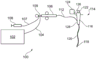
Fig. 1 is a schematic view of an electrosurgical ablation device 100 configured to supply microwave energy and fluid (e.g., cooling fluid) to a distal end of an invasive electrosurgical instrument. The system 100 includes a generator 102 for controllably supplying Radio Frequency (RF) energy and microwave energy. Generators suitable for this purpose are described in WO 2012/076844, which is incorporated herein by reference. The generator may be arranged to monitor the reflected signal received from the instrument in order to determine an appropriate power level for delivery. For example, the generator may be arranged to calculate the impedance observed at the distal end of the instrument in order to determine an optimal delivered power level.
The generator 102 is connected to an interface connector 106 by an interface cable 104. The interface fitting 106 is also connected to a fluid delivery device 108, such as a syringe, via a fluid flow line 107. In some examples, the device may additionally or alternatively be arranged to aspirate fluid from the treatment site. In this case, fluid flow line 107 may convey fluid away from interface fitting 106 to a suitable collector (not shown). The aspiration mechanism may be connected at the proximal end of the fluid flow line 107.
If desired, the interface adapter 106 may house an instrument control mechanism that is operable by sliding a trigger, for example, to control longitudinal (back and forth) movement of one or more control wires or pushrods (not shown). If there are multiple control lines, there may be multiple sliding triggers on the interface to provide full control. The function of the interface adapter 106 is to combine the inputs from the generator 102, the fluid delivery device 108, and the instrument control mechanism into a single flexible shaft 112 that extends from the distal end of the interface adapter 106.
The flexible shaft 112 may be inserted through the entire length of the instrument (working) channel of the surgical viewing device 114, which in embodiments of the present invention may comprise an endoscopic ultrasound device.
The surgical viewing device 114 includes a body 116 having a plurality of input ports and an output port from which an instrument string 120 extends. The instrument cable 120 includes an outer sheath surrounding a plurality of lumens. The plurality of lumens convey various substances from the body 116 to the distal end of the instrument string 120. One of the plurality of lumens is the instrument channel discussed above. Other lumens may include channels for delivering optical radiation, for example, to provide illumination at the distal end or to collect images from the distal end. The body 116 may include an eyepiece 122 for viewing the distal end.
Endoscopic ultrasound devices typically provide an ultrasound transducer on the distal end of the instrument string beyond the exit orifice of the instrument channel. The signals from the ultrasound transducer may be transmitted by a suitable cable 126 along the instrument string back to the processor 124, which may generate images in a known manner. The instrument channel may be shaped within an instrument string to guide an instrument exiting the instrument channel through a field of view of the ultrasound system to provide information about the position of the instrument at the target site.
The flexible shaft 112 has a distal assembly 118 (not drawn to scale in fig. 1) that is shaped to pass through an instrument channel of the surgical viewing device 114 and protrude at a distal end of the instrument cord (e.g., within the patient).
The structure of the distal assembly 118 discussed below may be specifically designed for use with an Endoscopic Ultrasound (EUS) device whereby the maximum outer diameter of the distal end assembly 118 is equal to or less than 2.0mm, such as less than 1.9mm (more preferably less than 1.5 mm), and the length of the flexible shaft may be equal to or greater than 1.2m.
The body 116 includes a power input port 128 for connection to the flexible shaft 112. As explained below, the proximal portion of the flexible shaft may include a conventional coaxial cable capable of transmitting radio frequency energy and microwave energy from the generator 102 to the distal assembly 118. The coaxial cable that can physically mate with the instrument channel of the EUS device has the following outer diameters: 1.19mm (0.047 inch), 1.35mm (0.053 inch), 1.40mm (0.055 inch), 1.60mm (0.063 inch), 1.78mm (0.070 inch). Custom sized coaxial cables (i.e., custom made) may also be used.
As discussed above, it is desirable to be able to control at least the position of the distal end of the instrument string 120. The body 116 may include a control actuator mechanically coupled to the distal end of the instrument string 120 by one or more control wires (not shown) extending through the instrument string 120. These control wires may run within the instrument channel or within their own dedicated channels. The control actuator may be a joystick or rotatable knob, or any other known catheter manipulation device. Manipulation of the instrument string 120 may be software assisted, for example using a virtual three-dimensional map assembled from Computed Tomography (CT) images.
Fig. 2 is a view looking down along the axis of instrument cable 120. In this embodiment, there are four lumens within the instrument cord 120. The largest lumen is the instrument channel 132. Other lumens include an ultrasound signal channel 134 and an illumination channel 136, and a camera channel 138, although the invention is not limited to this configuration. For example, there may be other lumens, such as for control wires or fluid delivery or aspiration.
In one embodiment, the present invention may provide an instrument that may perform tissue ablation at the distal end of an EUS system catheter. In order to reduce side effects and maximize the efficiency of the instrument, the transmitting antenna should be positioned as close as possible to the target tissue. Ideally, the radiating portion of the instrument is located inside the tumor (e.g., at the center of the tumor) during treatment.
The invention may be particularly suitable for treating the pancreas. To reach the target site, the instrument will need to be guided through the mouth, stomach and duodenum. The instrument is arranged to access the pancreas by passing through the duodenal wall. This procedure places a significant limit on the size of instruments that can be passed into the pancreas. Conventionally, instruments having an outer diameter of not more than 1mm (e.g., 19G) have been used.
The following description presents a variety of antenna configurations suitable for use in the described distal assembly 118.
In the following description, unless indicated otherwise, the length of a component refers to the dimension of the component in a direction parallel to the longitudinal axis of the coaxial cable/instrument cord.
Fig. 3 is a cross-sectional view of the distal end of an electrosurgical instrument 200 as one embodiment of the present invention. Fig. 3 shows the distal end portion of the instrument, which has three sections. The first section includes a coaxial cable 202 that extends to the proximal end of the instrument, such as through the instrument channel of the surgical viewing device as discussed above. The proximal end of the coaxial cable 202 may be connected to an electrosurgical generator to receive and transmit microwave energy, such as electromagnetic energy having a frequency of 5.8 GHz. The second section includes an intermediate impedance transformer 204. The third section includes a distal radiating section 206. The intermediate impedance transformer 204 is arranged to match the impedance of the coaxial cable 202 to the impedance of the distal radiating section 206.
The coaxial cable 202 may be conventionalHas an outer diameter selected to enable passage through an instrument channel of a surgical viewing device. In one example, the outer diameter of the coaxial cable 202 may be equal to or less than 2.2mm. For example, one can use 86 cable. The coaxial cable includes an
 inner conductor 208 separated from an outer conductor 212 by an insulating dielectric material 210. A protective jacket (not shown) may be disposed around the outer surface of the outer conductor 212. The length of the coaxial cable 202 may be 1.2m or greater. Only the distal portion thereof is shown in fig. 3.
In this embodiment, the inner conductor 208 of the coaxial cable 202 extends beyond the distal end of the outer conductor 212, through both the intermediate impedance transformer 204 and the distal radiating section 206. Thus, all three sections of the distal end assembly share a common inner conductor. Indeed, in one example, the intermediate impedance transformer 204 and the distal radiating section 206 may be formed by stripping the outer conductor from the distal section of the coaxial cable, selectively removing a portion of the dielectric material 210 to achieve the desired dielectric outer diameter of each section, and then providing a new outer conductor on the reduced diameter section. The intermediate impedance transformer 204 has a dielectric material 214 with a first reduced diameter and the distal radiating section 206 has a dielectric material 216 with a second reduced diameter. The first reduced diameter is less than the diameter of the dielectric material 210 in the coaxial cable 202. The second reduced diameter is smaller than the first reduced diameter. The relationship between these diameters will be discussed in more detail below.
In this embodiment, the distal radiating section 206 includes a loaded monopole antenna 218, which may be provided by removing an outer conductor from the distal-most length of the distal radiating section 206. The loaded monopole antenna 218 may have a length equal to an odd multiple of a quarter wavelength of microwave energy transmitted by the coaxial cable 202.
As discussed above, it is desirable that the maximum outer diameter of the distal radiating section 206 (which is the section to be inserted into the pancreas) be equal to or less than 1mm. In one example, this is achieved by the following lateral dimensions of the relevant components:
| component part | Outer diameter (mm) | Material |
| Inner conductor | 0.53(d 1 ) | Copper/silver plated steel |
| Dielectric medium | 0.85(d 2 ) | PTFE |
| Outer conductor | 1.00 | Copper (Cu) |
Table 1: the size of distal radiating section 206
In this example, the thickness of the outer conductor would be 0.075mm. The relative permittivity epsilon of the dielectric material used in this example r Is 1.85, which provides an impedance Z of the distal radiating section Outer part The following is shown:

accordingly, the impedance Z of the coaxial cable 202 is assumed Inner part 50 omega, then middleImpedance Z of the impedance transformer 204 t Is calculated as

Since in this example the same inner conductor and the same dielectric material are used in the intermediate impedance transformer 204, the outer diameter d of the dielectric material 214 can be calculated 3 To satisfy the relation:

solving the relation to obtain d 3 1.1mm. According to this value, the lateral dimensions of the relevant components in the intermediate impedance transformer 204 may be as follows:
| component part | Outer diameter (mm) | Material |
| Inner conductor | 0.53(d 1 ) | Copper/silver plated steel |
| Dielectric medium | 1.1(d 3 ) | PTFE |
| Outer conductor | 1.5 | Copper (Cu) |
Table 2: the size of the intermediate impedance transformer 204
The length of the intermediate impedance transformer 204 is preferably an odd multiple of one quarter wavelength of the microwave energy transmitted therein. At epsilon r In the case of 1.85mm, the quarter wavelength at 5.8GHz is 9.5mm.
The length of the loaded monopole antenna 218 may also be 9.5mm if the same dielectric material is used for the entire length of the instrument. However, the same dielectric material need not be used everywhere. For example, a different dielectric material may be used for the loaded monopole antenna 218. For example, the length of the loaded monopole antenna 218 may be reduced by using a dielectric material having a higher relative permittivity. In one example, a rigid dielectric material such as ceramic or Polyetheretherketone (PEEK) may be used. In other examples, the distal radiating section 206 may include a loadless antenna, e.g., including a portion of the exposed inner conductor. An example of such a structure is discussed below with reference to fig. 5.
The apparatus 200 discussed above provides a means of introducing microwave energy into the pancreas that may facilitate more accurate and efficient treatment than the radio frequency-based techniques heretofore used. In particular, the transmission mechanism by which energy is delivered into the device from the microwave antenna is mainly radiation. Thus, the target area is treated quickly and the risk of energy leakage or concentration in unwanted areas is reduced. This can be contrasted with RF-based techniques in which the transport mechanism is primarily by conduction, and in which case the use of externally positioned return pads can make the location of the current path difficult to control.
Although the devices disclosed herein may be particularly suitable for use with microwave energy, the devices may also provide a bipolar structure for delivering Radio Frequency (RF) energy. In one example, the same structure that forms an antenna for radiating microwave energy provides an active electrode and a return electrode that are adapted to deliver RF energy therebetween. The active electrode may be an inner conductor. The return electrode may be a distal portion of the outer conductor. This arrangement provides a local return path for RF current and may therefore be preferred over prior art instruments that require a separate external return pad. In other examples, the instrument may include separate structures for delivering RF energy.
As discussed above, the instrument may be connected to a generator that may deliver RF energy and microwave energy along a coaxial transmission line separately or simultaneously. Thus, the instrument may be selectively operable in a plurality of treatment modes including, for example, any one, two, three or more of the following: (i) microwave only, (ii) RF only, (iii) microwave after RF, (iv) RF after microwave, (v) RF and microwave simultaneously. Thus, the instrument is capable of treatment under more complex energy application mechanisms than conventional RF ablation devices.
Fig. 4 is a cross-sectional view of the distal end of an electrosurgical instrument 240 as another embodiment of the present invention. Features common to the embodiment shown in fig. 3 are given the same reference numerals and will not be discussed again. Similar to fig. 3, instrument 240 utilizes a common inner conductor from coaxial cable 202 through intermediate impedance transformer 204 and distal radiating section 206. However, in this embodiment, the dielectric material of the coaxial cable 202 may be completely removed and replaced with an alternative material in the intermediate impedance transformer 204 and the distal radiating section 206.
It may be desirable for the distal portion of the instrument to be rigid in order to assist in pushing the instrument into the tumor to be treated. Accordingly, the intermediate impedance transformer 204 and the distal radiating section 206 may each be provided with a rigid dielectric material 242, 244. The rigid dielectric materials 242, 244 in the section may be the same or different. For example, the intermediate impedance transformer 204 may have a dielectric material 242 formed of PEEK, while the distal radiating section 206 may have a dielectric material 244 formed of ceramic, and vice versa. As explained above, an advantage of these materials is that they have a higher relative permittivity than the dielectric material 210 of the coaxial cable 202, which enables the distal portion to be compact. The rigid dielectric materials 242, 244 may be molded around or otherwise mounted on the inner conductor 208 after the dielectric material 210 is peeled from the inner conductor. As discussed above, after the rigid dielectric materials 242, 244 are in place, a new outer conductor is applied over the intermediate impedance transformer 204 and the relevant portion of the distal radiating section 206.
In a particular example having the structure shown in fig. 4, the intermediate dielectric material 242 and the distal dielectric material are both PEEK. The distal radiating section 206 has a total length of 3 cm. The outer metallization 244 extends over 2cm of the total length to leave a 1cm portion of the exposed PEEK furthest distally (with the inner conductor extending therein). The outer metallization 244 has an inner diameter of 0.8mm and an outer diameter of 1.0 mm.
Fig. 5 is a cross-sectional view of the distal end of an electrosurgical instrument 260 as another embodiment of the present invention. Features common to the embodiment shown in fig. 3 are given the same reference numerals and will not be discussed again. In this example, an inner conductor 208 from the coaxial cable 202 extends through the intermediate impedance transformer 204 and terminates at a proximal end of the distal radiating section 206. A rigid conductive finger 266 is mounted on and electrically connected to the distal end of the inner conductor 208. In this example, the rigid conductive fingers 266 form the inner conductor of the distal radiating section 206 and protrude therefrom as a no-load monopole antenna 268. The protruding portion is sharpened, e.g. similar to a needle, to facilitate insertion into tissue. The rigid conductive fingers 266 may be made of stainless steel or the like.
In this example, the dielectric materials 262, 264 used in the intermediate impedance transformer 204 and the distal radiating section 206 are different from the dielectric material 210 of the coaxial cable 202. As discussed above with reference to fig. 4, these materials may be selected to impart desired physical properties (e.g., stiffness) or to control the length of the corresponding portion of the instrument. In the example shown, the outer diameter of the rigid conductive fingers 266 may be greater than the outer diameter of the inner conductor 208, which will have an effect on the impedance of the distal portion.
Fig. 6 is a cross-sectional view of the distal end of an electrosurgical instrument 280 as another embodiment of the present invention. Features common to the embodiment shown in fig. 3 are given the same reference numerals and will not be discussed again. In this example, the distal radiating section 206 includes a slotted antenna structure 286. Similar to fig. 3, instrument 280 utilizes a common inner conductor from coaxial cable 202 passing through intermediate impedance transformer 204 and distal radiating section 206. In this embodiment, the dielectric material of the coaxial cable 202 may be completely removed and replaced with an alternative material in the intermediate impedance transformer 204 and the distal radiating section 206. The intermediate impedance transformer 204 has an intermediate dielectric material 282 and the distal radiating section 206 has a distal dielectric material 284. The intermediate dielectric material 282 and the distal dielectric material 284 may be the same or different. They may all be different from the dielectric material 210 of the coaxial cable.
In order to provide a compact slotted antenna, it may be desirable for the distal dielectric material 284 to provide a high load to the structure, for example by having a dielectric constant equal to or greater than 20, preferably equal to or greater than 40. The slotted antenna 286 is formed by creating one or more windows or slots 288 in the outer conductive layer on the distal radiating section 206. Where multiple slots are formed, half wavelengths of microwave energy transmitted by the distal radiating section 206 are separated along the length of the distal radiating section 206. To generate an elongated (i.e., forward-directed) ablation field, the distal end of the inner conductor 208 may be electrically connected to an external conductive layer on the distal radiating section 206, for example, via a conductive end cap 290. The distal-most slot on the distal radiating section 206 is preferably spaced from the distal end (e.g., end cap 290) by a quarter wavelength of the microwave energy transmitted by the distal radiating section 206. In one example, dielectric material 284 may have a relative permittivity of 49, whereby a quarter wavelength of microwave energy at a frequency of 5.8GHz is 1.85mm. In this example, the slots are spaced apart at a pitch of 3.7mm along the length of the distal radiating section 206.
In use, an instrument according to any of the examples listed above may be inserted through an instrument channel of a surgical viewing device to reach a treatment site, such as through the duodenal wall into the pancreas. The distal radiating section 206 may penetrate tissue such that microwave energy delivered by the coaxial cable 202 is radiated into the tissue to ablate the tissue.
In some procedures, an aspiration needle may be inserted into the treatment site prior to the instrument, for example, to remove fluid from a cyst or the like.
The instrument of the invention can be used in particular as an alternative to the known RF ablation technique, in particular because the instrument has a size of the same order of magnitude as the known RF probe and can therefore be introduced using the same equipment.
Claims (17)
1. An electrosurgical instrument, comprising:
a proximal portion comprising a coaxial transmission line for transmitting microwave Electromagnetic (EM) energy, wherein the coaxial transmission line comprises an inner conductor separated from a proximal outer conductor by a first dielectric material;
a distal radiating section; and
an intermediate impedance transformer arranged to match the impedance of the coaxial transmission line with the impedance of the distal radiating section,
wherein the inner conductor extends beyond a distal end of the proximal outer conductor, through the intermediate impedance transformer and through the distal radiating section to form a conductive section of a microwave antenna for transmitting the microwave EM energy transmitted by the coaxial transmission line,
wherein the microwave antenna comprises a distal dielectric material mounted on the conductive portion of the microwave antenna,
wherein the distal radiating section defines an exterior surface of the electrosurgical instrument and has a maximum outer diameter that is less than an outer diameter of the coaxial transmission line, an
Wherein the distal dielectric material has a maximum outer diameter that is less than an outer diameter of the first dielectric material.
2. The electrosurgical instrument of claim 1, wherein the intermediate impedance transformer is a quarter-wavelength coaxial transmission line.
3. The electrosurgical instrument of claim 2, wherein in the quarter wavelength coaxial transmission line, the inner conductor is separated from an intermediate outer conductor by a second dielectric material having a smaller outer diameter than the first dielectric material.
4. The electrosurgical instrument of claim 3, wherein the second dielectric material is a reduced diameter portion of the first dielectric material that extends beyond the distal end of the proximal outer conductor.
5. The electrosurgical instrument of claim 3, wherein the second dielectric material has a higher relative permittivity than the first dielectric material.
6. An electrosurgical instrument according to any preceding claim, wherein the microwave antenna is a loaded monopole antenna.
7. The electrosurgical instrument according to any preceding claim, wherein the distal dielectric material is a reduced diameter portion of the first dielectric material that extends beyond the distal end of the proximal outer conductor.
8. The electrosurgical instrument according to any one of claims 1 to 6, wherein the distal dielectric material is a rigid material having a higher relative permittivity than the first dielectric material.
9. An electrosurgical instrument according to any preceding claim, wherein the distal end of the microwave antenna is sharpened to facilitate insertion into tissue.
10. The electrosurgical instrument according to any one of claims 1 to 5, wherein the microwave antenna is a slotted antenna.
11. The electrosurgical instrument of claim 10, wherein the distal radiating section comprises a distal coaxial transmission line having a distal inner conductor separated from a distal outer conductor by the distal dielectric material, and wherein the slotted antenna is formed by removing portions of the distal outer conductor.
12. The electrosurgical instrument of claim 11, wherein the distal inner conductor is electrically connected to the distal outer conductor at a distal tip of the microwave antenna.
13. The electrosurgical instrument according to any preceding claim, wherein the distal radiating section comprises a bipolar structure for delivering Radio Frequency (RF) energy.
14. The electrosurgical instrument of claim 13, wherein the bipolar structure is formed by the microwave antenna.
15. An electrosurgical apparatus, comprising:
a surgical viewing device having an instrument cable configured to be insertable into a patient, wherein the instrument cable has an instrument channel formed therethrough; and
an electrosurgical instrument according to any preceding claim, sized to be insertable through the instrument channel.
16. The electrosurgical apparatus of claim 15, wherein the surgical viewing device is an endoscopic ultrasound device.
17. The electrosurgical apparatus of claim 15, further comprising an electrosurgical generator connected to supply Radio Frequency (RF) energy and microwave energy to the coaxial transmission line separately or simultaneously, wherein the instrument is selectively operable in a plurality of treatment modes including any one of: (i) microwave only, (ii) RF only, (iii) microwave after RF, (iv) RF after microwave, (v) RF and microwave simultaneously.
Priority Applications (2)
| Application Number | Priority Date | Filing Date | Title |
|---|---|---|---|
| CN202310391035.1A CN116370065A (en) | 2017-12-27 | 2018-12-20 | Electrosurgical ablation instrument |
| CN202310381057.XA CN116370064A (en) | 2017-12-27 | 2018-12-20 | Electrosurgical ablation instrument |
Applications Claiming Priority (3)
| Application Number | Priority Date | Filing Date | Title |
|---|---|---|---|
| GB1721995.7 | 2017-12-27 | ||
| GB1721995.7A GB2569812A (en) | 2017-12-27 | 2017-12-27 | Electrosurgical ablation instrument |
| PCT/EP2018/086237 WO2019129648A1 (en) | 2017-12-27 | 2018-12-20 | Electrosurgical ablation instrument |
Related Child Applications (2)
| Application Number | Title | Priority Date | Filing Date |
|---|---|---|---|
| CN202310381057.XA Division CN116370064A (en) | 2017-12-27 | 2018-12-20 | Electrosurgical ablation instrument |
| CN202310391035.1A Division CN116370065A (en) | 2017-12-27 | 2018-12-20 | Electrosurgical ablation instrument |
Publications (2)
| Publication Number | Publication Date |
|---|---|
| CN111565663A CN111565663A (en) | 2020-08-21 |
| CN111565663B true CN111565663B (en) | 2023-04-28 |
Family
ID=61131530
Family Applications (3)
| Application Number | Title | Priority Date | Filing Date |
|---|---|---|---|
| CN201880076180.8A Active CN111565663B (en) | 2017-12-27 | 2018-12-20 | Electrosurgical ablation instrument |
| CN202310381057.XA Pending CN116370064A (en) | 2017-12-27 | 2018-12-20 | Electrosurgical ablation instrument |
| CN202310391035.1A Pending CN116370065A (en) | 2017-12-27 | 2018-12-20 | Electrosurgical ablation instrument |
Family Applications After (2)
| Application Number | Title | Priority Date | Filing Date |
|---|---|---|---|
| CN202310381057.XA Pending CN116370064A (en) | 2017-12-27 | 2018-12-20 | Electrosurgical ablation instrument |
| CN202310391035.1A Pending CN116370065A (en) | 2017-12-27 | 2018-12-20 | Electrosurgical ablation instrument |
Country Status (15)
| Country | Link |
|---|---|
| US (1) | US20200360085A1 (en) |
| EP (3) | EP3988044A1 (en) |
| JP (3) | JP7280626B2 (en) |
| KR (1) | KR20200102989A (en) |
| CN (3) | CN111565663B (en) |
| AU (1) | AU2018394011A1 (en) |
| BR (1) | BR112020010666A2 (en) |
| CA (1) | CA3084509A1 (en) |
| DK (1) | DK3731776T3 (en) |
| ES (1) | ES2910014T3 (en) |
| GB (1) | GB2569812A (en) |
| IL (1) | IL274792A (en) |
| PT (1) | PT3731776T (en) |
| SG (1) | SG11202004756WA (en) |
| WO (1) | WO2019129648A1 (en) |
Families Citing this family (7)
| Publication number | Priority date | Publication date | Assignee | Title |
|---|---|---|---|---|
| GB2576481B (en) * | 2018-05-30 | 2022-07-20 | Creo Medical Ltd | Electrosurgical instrument |
| GB2583715A (en) * | 2019-04-30 | 2020-11-11 | Creo Medical Ltd | Electrosurgical system |
| GB2583490A (en) * | 2019-04-30 | 2020-11-04 | Creo Medical Ltd | Electrosurgical system |
| CA3132063A1 (en) * | 2019-05-17 | 2020-11-26 | Boston Scientific Scimed, Inc. | Medical imaging devices and systems |
| GB2589589A (en) * | 2019-12-03 | 2021-06-09 | Creo Medical Ltd | Electrosurgical instrument |
| GB2594438A (en) * | 2019-12-05 | 2021-11-03 | Creo Medical Ltd | Electrosurgical instrument, generator and apparatus |
| US20220031390A1 (en) * | 2020-07-31 | 2022-02-03 | Medtronic, Inc. | Bipolar tool for separating tissue adhesions or tunneling |
Citations (3)
| Publication number | Priority date | Publication date | Assignee | Title |
|---|---|---|---|---|
| CN102711643A (en) * | 2009-11-17 | 2012-10-03 | Bsd医药公司 | Microwave coagulation applicator and system |
| CA2878570A1 (en) * | 2012-08-07 | 2014-02-13 | Covidien Lp | Microwave ablation catheter and method of utilizing the same |
| CA2962434A1 (en) * | 2014-10-01 | 2016-04-07 | Covidien Lp | Miniaturized microwave ablation assembly |
Family Cites Families (17)
| Publication number | Priority date | Publication date | Assignee | Title |
|---|---|---|---|---|
| US5861021A (en) * | 1996-06-17 | 1999-01-19 | Urologix Inc | Microwave thermal therapy of cardiac tissue |
| US5707452A (en) * | 1996-07-08 | 1998-01-13 | Applied Microwave Plasma Concepts, Inc. | Coaxial microwave applicator for an electron cyclotron resonance plasma source |
| US6325796B1 (en) * | 1999-05-04 | 2001-12-04 | Afx, Inc. | Microwave ablation instrument with insertion probe |
| ITPI20010006A1 (en) | 2001-01-31 | 2002-07-31 | Cnr Consiglio Naz Delle Ricer | INTERSTITIAL ANTENNA WITH MINIATURIZED CHOKE FOR MICROWAVE HYPERTEMIA APPLICATIONS IN MEDICINE AND SURGERY |
| ITMO20050034A1 (en) | 2005-02-11 | 2006-08-12 | Hs Hospital Service Spa | MICROWAVE DEVICE FOR FABRIC APPLICATION. |
| US11666377B2 (en) * | 2006-09-29 | 2023-06-06 | Boston Scientific Medical Device Limited | Electrosurgical device |
| US8282632B2 (en) * | 2009-09-28 | 2012-10-09 | Vivant Medical, Inc. | Feedpoint optimization for microwave ablation dipole antenna with integrated tip |
| GB201021032D0 (en) | 2010-12-10 | 2011-01-26 | Creo Medical Ltd | Electrosurgical apparatus |
| US9358066B2 (en) * | 2011-04-08 | 2016-06-07 | Covidien Lp | Flexible microwave catheters for natural or artificial lumens |
| US8870860B2 (en) * | 2011-08-09 | 2014-10-28 | Covidien Lp | Microwave antenna having a coaxial cable with an adjustable outer conductor configuration |
| CN108542496B (en) * | 2012-03-31 | 2021-12-07 | 微立方有限责任公司 | Return power for microwave applications |
| US8906008B2 (en) * | 2012-05-22 | 2014-12-09 | Covidien Lp | Electrosurgical instrument |
| US9144459B2 (en) * | 2012-07-19 | 2015-09-29 | Cook Medical Technologies Llc | Endoscopic ultrasound ablation needle |
| US9610122B2 (en) | 2013-03-29 | 2017-04-04 | Covidien Lp | Step-down coaxial microwave ablation applicators and methods for manufacturing same |
| GB201418479D0 (en) | 2014-10-17 | 2014-12-03 | Creo Medical Ltd | Cable for conveying radiofrequency and/or microwave frequency energy to an electrosurgical instrument |
| US11058486B2 (en) * | 2016-02-11 | 2021-07-13 | Covidien Lp | Systems and methods for percutaneous microwave ablation |
| GB2552921A (en) | 2016-04-04 | 2018-02-21 | Creo Medical Ltd | Electrosurgical probe for delivering RF and microwave energy |
-
2017
- 2017-12-27 GB GB1721995.7A patent/GB2569812A/en not_active Withdrawn
-
2018
- 2018-12-20 CA CA3084509A patent/CA3084509A1/en active Pending
- 2018-12-20 CN CN201880076180.8A patent/CN111565663B/en active Active
- 2018-12-20 AU AU2018394011A patent/AU2018394011A1/en active Pending
- 2018-12-20 SG SG11202004756WA patent/SG11202004756WA/en unknown
- 2018-12-20 CN CN202310381057.XA patent/CN116370064A/en active Pending
- 2018-12-20 DK DK18827087.0T patent/DK3731776T3/en active
- 2018-12-20 US US16/766,422 patent/US20200360085A1/en active Pending
- 2018-12-20 WO PCT/EP2018/086237 patent/WO2019129648A1/en active Search and Examination
- 2018-12-20 KR KR1020207014371A patent/KR20200102989A/en not_active Application Discontinuation
- 2018-12-20 EP EP21213841.6A patent/EP3988044A1/en active Pending
- 2018-12-20 CN CN202310391035.1A patent/CN116370065A/en active Pending
- 2018-12-20 EP EP18827087.0A patent/EP3731776B1/en active Active
- 2018-12-20 BR BR112020010666-6A patent/BR112020010666A2/en unknown
- 2018-12-20 JP JP2020529212A patent/JP7280626B2/en active Active
- 2018-12-20 EP EP21213905.9A patent/EP4000549A1/en active Pending
- 2018-12-20 PT PT188270870T patent/PT3731776T/en unknown
- 2018-12-20 ES ES18827087T patent/ES2910014T3/en active Active
-
2020
- 2020-05-20 IL IL274792A patent/IL274792A/en unknown
-
2023
- 2023-05-02 JP JP2023075979A patent/JP2023100819A/en active Pending
- 2023-05-02 JP JP2023075978A patent/JP2023100818A/en active Pending
Patent Citations (4)
| Publication number | Priority date | Publication date | Assignee | Title |
|---|---|---|---|---|
| CN102711643A (en) * | 2009-11-17 | 2012-10-03 | Bsd医药公司 | Microwave coagulation applicator and system |
| CA2878570A1 (en) * | 2012-08-07 | 2014-02-13 | Covidien Lp | Microwave ablation catheter and method of utilizing the same |
| WO2014025549A1 (en) * | 2012-08-07 | 2014-02-13 | Covidien Lp | Microwave ablation catheter and method of utilizing the same |
| CA2962434A1 (en) * | 2014-10-01 | 2016-04-07 | Covidien Lp | Miniaturized microwave ablation assembly |
Also Published As
| Publication number | Publication date |
|---|---|
| EP3988044A1 (en) | 2022-04-27 |
| EP3731776A1 (en) | 2020-11-04 |
| JP2023100819A (en) | 2023-07-19 |
| CN111565663A (en) | 2020-08-21 |
| CN116370064A (en) | 2023-07-04 |
| SG11202004756WA (en) | 2020-07-29 |
| GB201721995D0 (en) | 2018-02-07 |
| RU2020117031A3 (en) | 2022-01-27 |
| JP2023100818A (en) | 2023-07-19 |
| EP4000549A1 (en) | 2022-05-25 |
| JP7280626B2 (en) | 2023-05-24 |
| CA3084509A1 (en) | 2019-07-04 |
| BR112020010666A2 (en) | 2020-11-10 |
| AU2018394011A1 (en) | 2020-06-04 |
| ES2910014T3 (en) | 2022-05-11 |
| WO2019129648A1 (en) | 2019-07-04 |
| JP2021509594A (en) | 2021-04-01 |
| GB2569812A (en) | 2019-07-03 |
| US20200360085A1 (en) | 2020-11-19 |
| PT3731776T (en) | 2022-04-05 |
| KR20200102989A (en) | 2020-09-01 |
| DK3731776T3 (en) | 2022-03-28 |
| EP3731776B1 (en) | 2022-02-23 |
| IL274792A (en) | 2020-07-30 |
| CN116370065A (en) | 2023-07-04 |
| RU2020117031A (en) | 2022-01-27 |
Similar Documents
| Publication | Publication Date | Title |
|---|---|---|
| CN111565663B (en) | Electrosurgical ablation instrument | |
| CN109069201B (en) | Electrosurgical probe for delivering RF and microwave energy | |
| US20220202490A1 (en) | Electrosurgical system | |
| AU2019370592A1 (en) | Electrosurgical instrument | |
| CA3119863A1 (en) | Electrosurgical instrument | |
| EP3796859B1 (en) | Electrosurgical ablation instrument | |
| RU2772683C2 (en) | Electrosurgical ablative instrument | |
| RU2777551C2 (en) | Electrosurgical instrument for ablation | |
| EP3962392B1 (en) | Electrosurgical system | |
| GB2605551A (en) | Handpiece for an electrosurgical instrument |
Legal Events
| Date | Code | Title | Description |
|---|---|---|---|
| PB01 | Publication | ||
| PB01 | Publication | ||
| SE01 | Entry into force of request for substantive examination | ||
| SE01 | Entry into force of request for substantive examination | ||
| REG | Reference to a national code |
Ref country code: HK Ref legal event code: DE Ref document number: 40034159 Country of ref document: HK |
|
| GR01 | Patent grant | ||
| GR01 | Patent grant |