CN111546432B - Automatic plate punching equipment - Google Patents
Automatic plate punching equipment Download PDFInfo
- Publication number
- CN111546432B CN111546432B CN202010456393.2A CN202010456393A CN111546432B CN 111546432 B CN111546432 B CN 111546432B CN 202010456393 A CN202010456393 A CN 202010456393A CN 111546432 B CN111546432 B CN 111546432B
- Authority
- CN
- China
- Prior art keywords
- feeding
- lifting
- face
- fixedly arranged
- fixed
- Prior art date
- Legal status (The legal status is an assumption and is not a legal conclusion. Google has not performed a legal analysis and makes no representation as to the accuracy of the status listed.)
- Active
Links
Images


Classifications
-
- B—PERFORMING OPERATIONS; TRANSPORTING
- B27—WORKING OR PRESERVING WOOD OR SIMILAR MATERIAL; NAILING OR STAPLING MACHINES IN GENERAL
- B27C—PLANING, DRILLING, MILLING, TURNING OR UNIVERSAL MACHINES FOR WOOD OR SIMILAR MATERIAL
- B27C3/00—Drilling machines or drilling devices; Equipment therefor
- B27C3/02—Stationary drilling machines with a single working spindle
-
- B—PERFORMING OPERATIONS; TRANSPORTING
- B27—WORKING OR PRESERVING WOOD OR SIMILAR MATERIAL; NAILING OR STAPLING MACHINES IN GENERAL
- B27G—ACCESSORY MACHINES OR APPARATUS FOR WORKING WOOD OR SIMILAR MATERIALS; TOOLS FOR WORKING WOOD OR SIMILAR MATERIALS; SAFETY DEVICES FOR WOOD WORKING MACHINES OR TOOLS
- B27G3/00—Arrangements for removing bark-zones, chips, waste, or dust, specially designed for use in connection with wood-working machine or in wood-working plants
Abstract
The invention discloses automatic plate punching equipment which comprises a workbench, wherein a hydraulic box is arranged at the upper end of the left side of the workbench, a punching mechanism is arranged on the right side of the hydraulic box, the punching mechanism comprises a hydraulic cylinder fixed in the hydraulic box, and a hydraulic rod capable of stretching rightwards is arranged at the right end of the hydraulic cylinder.
Description
Technical Field
The invention relates to the field of punching machines, in particular to automatic plate punching equipment.
Background
At present, for the increase of the demand of furniture in the society at present, the punching precision requirement on some special plates is higher and higher, the punching position precision requirement of some punching equipment in the market at present is not high enough, so that the produced plates have defects in the quality of produced products caused by hole position deviation in the installation process, and the problem that the drilling precision and the production efficiency are influenced by residual sawdust in the hole position processing process of the plates in the market is solved.
Disclosure of Invention
The technical problem is as follows:
some improvements should be made in time to the hole site deviation that causes to the old and old puncher equipment on the market, phenomenon that production efficiency is low, and survey discovery is not high to the degree of automation of old facility, and the saw-dust that produces in the production process can cause the influence to drilling precision and punching efficiency.
In order to solve the problems, the embodiment designs an automatic punching device for plates, which comprises a workbench, wherein a hydraulic box is arranged at the upper end of the left side of the workbench, a punching mechanism is arranged at the right side of the hydraulic box and comprises a hydraulic cylinder fixed in the hydraulic box, a hydraulic rod capable of stretching rightwards is arranged at the right end of the hydraulic cylinder, a punching box capable of moving leftwards and rightwards is arranged at the right end of the hydraulic rod, a drill clamping jaw is rotatably connected at the lower end of the right wall of the punching box, a drill is fixedly arranged in the right end surface of the drill clamping jaw, a lifting platform is arranged on the end surface of the right side of the workbench, a lifting device is arranged on the upper end surface of the lifting platform, a bearing plate is fixedly arranged at the upper end of the lifting device, the lifting device can realize the up-down movement of the bearing plate, an auxiliary plate and a main plate are, the support bracket capable of moving back and forth on the main board is arranged on the right side of the drilling cavity, the support bracket is arranged on the right side of the main board and is provided with positioning holes which are penetrated left and right and are symmetrical up and down, the support bracket can move back and forth along the positioning holes, a feeding box is fixedly arranged on the front side of the support bracket and is positioned on the left end face of the main board, materials can be placed in the feeding box, a feeding box fixedly connected with the left end face of the main board is arranged on the front side of the feeding box, a feeding cavity is arranged in the feeding box, a feeding motor is fixedly arranged on the lower side of the front wall face of the feeding cavity, the rear end of the feeding motor is in power connection with a lead screw, a feeding block capable of moving back and forth in the feeding cavity is in threaded connection with the outer circular face of the lead, the carrier can drag the material and push the material to the support bracket and compress tightly, two sawdust holes which are penetrated left and right are distributed on the right side of the drill hole cavity and are arranged in the main board up and down, a centrifugal fan which is fixedly connected to the right end face of the main board is arranged on the right side of the sawdust holes, a recovery pipe which is communicated with the centrifugal fan is arranged on the right side of the centrifugal fan, the sawdust which falls off can be adsorbed rightwards through the sawdust holes and collected through an opening at the right end of the recovery pipe, a discharging device is arranged on the lower side between the auxiliary board and the main board, and the material which is drilled with the sawdust holes can be transported backwards and collected.
Preferably, the punching box is internally provided with a drilling motor fixed on the upper side, the right side of the drilling motor is provided with a spur gear cavity, a driving spur gear connected with the drilling motor in a power mode is arranged above the spur gear cavity, a driven spur gear meshed with each other is arranged under the driving spur gear, and the left end face of the drill clamping jaw is fixedly connected with the axis of the right end face of the driven spur gear in a shaft center mode.
Preferably, the lifting device comprises a fixed block fixed on the upper end surface of the lifting platform, main lifting rods are symmetrically arranged on the left and right sides close to the fixed block, the upper ends of the main lifting rods are hinged to the lower end surface of the bearing plate, fixing rods are fixedly arranged between the lower ends of the main lifting rods in bilateral symmetry, rolling rollers are arranged in the main lifting rods at the left and right ends of the fixing rods, sliding grooves fixedly connected to the upper end surface of the lifting platform are arranged on the lower sides of the rollers, a lifting hydraulic cylinder is fixedly arranged on the rear side of the fixing rods, a telescopic lifting hydraulic rod is connected with the opening of the lifting hydraulic cylinder in a backward power mode, the rear end surface of the hydraulic lifting rod is fixedly connected with the front end surface of the fixed block, an auxiliary lifting rod is symmetrically arranged on one side of the main lifting rod far away from the fixed block, and the auxiliary lifting rod on the same side is hinged, the lower end of the auxiliary lifting rod is positioned on the lifting platform, a hinge block is fixedly arranged on the lifting platform, the hinge block is hinged with the lower end of the auxiliary lifting rod, and the upper end of the auxiliary lifting rod, which is positioned on the front side, can slide back and forth.
Preferably, slide rails which are bilaterally symmetrical are fixedly arranged on the front side of the lower end face of the bearing plate, slide holes are formed in the left side and the right side of each slide rail in a penetrating mode, the upper end of the auxiliary lifting rod is connected with the slide rails through pins, and the pins can slide back and forth in the slide holes.
Preferably, a feeding spring is fixedly arranged between the right end face of the material placed in the feeding box and the left wall face of the feeding box, feeding holes are formed in the front side wall and the rear side wall of the right end of the feeding box in a penetrating mode, and the carrier can stretch into the feeding holes and bear the material.
Preferably, a positioning bolt capable of sliding back and forth is arranged in the positioning hole, and the positioning bolt can fix the support bracket at any position of the positioning hole.
Preferably, a driving bevel gear is fixedly arranged on the rear side of the feeding motor and on the outer circular surface of the screw rod, a bearing block fixed on the lower wall of the feeding cavity is arranged on the right side of the driving bevel gear, a first transmission shaft penetrates through the bearing block from left to right and is rotatably connected with the upper end of the bearing block, a driven bevel gear meshed with the driving bevel gear is fixedly arranged at the left end of the first transmission shaft, a ratchet wheel rotatably connected with the right wall of the feeding cavity is fixedly arranged at the right end of the first transmission shaft, a transmission shaft penetrating through the main board is fixedly arranged at the axis of the right end face of the ratchet wheel, and a driving.
Preferably, the discharging device comprises symmetrical rotary drums arranged at the front end and the rear end between the auxiliary plate and the main plate, a conveying belt is wound between the rotary drums, the front side of the rotary drums is fixedly provided with a second transmission shaft, the right end of the second transmission shaft extends to the right side of the main plate and is fixedly connected with a driven belt wheel, and a transmission belt is wound between the driven belt wheel and the driving belt wheel.
The invention has the beneficial effects that: according to the automatic punching machine, the hydraulic cylinder is driven to push the punching box to reciprocate left and right to precisely punch a material to be punched, the material can be precisely punched by adjusting up, down, left and right, so that the punching precision of a product is improved, the saw dust can be timely collected by installing the centrifugal fan, the 5S in the production process is improved, the workload of operators is reduced by automatic feeding and finished product conveying, the influence of saw dust accumulation on subsequent production is avoided, and the production efficiency is improved.
Drawings
For ease of illustration, the invention is described in detail by the following specific examples and figures.
FIG. 1 is a schematic view of the overall structure of an automatic plate punching apparatus according to the present invention;
FIG. 2 is a schematic view of the structure in the direction "A-A" of FIG. 1;
FIG. 3 is a schematic view of the structure in the direction "B-B" of FIG. 1;
FIG. 4 is a schematic view of the structure in the direction "C-C" of FIG. 1;
FIG. 5 is a schematic view of the structure in the direction "D-D" of FIG. 1;
FIG. 6 is a schematic view of the structure in the direction "E-E" of FIG. 3;
FIG. 7 is a schematic view of the structure in the direction "F-F" of FIG. 1;
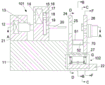
FIG. 8 is an enlarged view of the structure of "G" of FIG. 1;
FIG. 9 is an enlarged view of the structure of "H" in FIG. 4;
FIG. 10 is a schematic view of the structure in the direction "I-I" of FIG. 4.
Detailed Description
The invention will now be described in detail with reference to fig. 1-10, for ease of description, the orientations described below will now be defined as follows: the up, down, left, right, and front-back directions described below correspond to the up, down, left, right, and front-back directions in the projection relationship of fig. 1 itself.
The invention relates to automatic plate punching equipment which comprises a workbench 11, wherein a hydraulic tank 21 is arranged at the upper left side of the workbench 11, a punching mechanism 101 is arranged at the right side of the hydraulic tank 21, the punching mechanism 101 comprises a hydraulic cylinder 12 fixed in the hydraulic tank 21, a hydraulic rod 13 capable of stretching rightwards is arranged at the right end of the hydraulic cylinder 12, a punching tank 15 capable of moving leftwards and rightwards is arranged at the right end of the hydraulic rod 13, a drill clamping jaw 19 is rotatably connected to the lower end of the right wall of the punching tank 15, a drill 20 is fixedly arranged in the right end face of the drill clamping jaw 19, a lifting table 22 is arranged on the right end face of the workbench 11, a lifting device 102 is arranged on the upper end face of the lifting table 22, a bearing plate 27 is fixedly arranged on the upper end of the lifting device 102, the lifting device 102 can realize the up-down movement of the bearing plate 27, an auxiliary plate 24 and a, the right side of the drill 20 is provided with a drilling cavity 25 which penetrates through the auxiliary plate 24 from left to right, the right side of the drilling cavity 25 is provided with a supporting bracket 45 which can move back and forth on the main plate 26, the right side of the supporting bracket 45 is positioned on the main plate 26 and is provided with positioning holes 39 which penetrate through from left to right and are symmetrical up and down, the supporting bracket 45 can move back and forth along the positioning holes 39, the front side of the supporting bracket 45 is positioned on the left end face of the main plate 26 and is fixedly provided with a feeding box 43, materials 42 can be placed in the feeding box 43, the front side of the feeding box 43 is provided with a feeding box 41 which is fixedly connected with the left end face of the main plate 26, a feeding cavity 71 is arranged in the feeding box 41, the lower side of the front wall of the feeding cavity 71 is fixedly provided with a feeding motor 55, the rear end of the feeding motor 55 is, a push rod 61 is fixedly arranged on the rear end surface of the feeding block 60, the rear end of the push rod 61 extends out of the rear end surface of the feeding box 41 and is fixedly connected with a carrier 57, the carrier 57 can drag the material 42 and push the material 42 onto the support bracket 45 and compress it, two wood chip holes 40 which penetrate through from left to right are distributed right and above and below the drilling hole 25 in the main board 26, the right side of the wood chip hole 40 is provided with a centrifugal fan 46 fixedly connected with the right end face of the main board 26, a recycling pipe 47 communicated with the right side of the centrifugal fan 46 is arranged on the right side of the centrifugal fan 46, the centrifugal fan 46 can absorb the fallen wood chips to the right through the wood chip holes 40 and collect the wood chips through an opening at the right end of the recycling pipe 47, a discharging device 104 is arranged at the lower side between the auxiliary plate 24 and the main plate 26, and the discharging device 104 can convey and collect the punched materials 42 backwards.
Beneficially, including the drilling motor 14 that is fixed in the upside in the punching case 15, drilling motor 14 right side is equipped with straight gear chamber 16, straight gear chamber 16 top be equipped with drilling motor 14 power connection's initiative spur gear 17, be equipped with driven spur gear 18 of intermeshing under the initiative spur gear 17, drill bit clamping jaw 19 left end face with driven spur gear 18 right-hand member face axle center position fixed connection.
Beneficially, the lifting device 102 includes a fixed block 76 fixed on the upper end surface of the lifting table 22, main lifting rods 34 are symmetrically arranged on the left and right sides close to the fixed block 76, the upper ends of the main lifting rods 34 are hinged to the lower end surface of the supporting plate 27, fixing rods 37 are fixedly arranged between the lower ends of the main lifting rods 34 which are bilaterally symmetric, rolling rollers 36 are arranged at the left and right ends of the fixing rods 37 and located in the main lifting rods 34, sliding grooves 33 fixedly connected to the upper end surface of the lifting table 22 are arranged on the lower sides of the rollers 36, a lifting hydraulic cylinder 38 is fixedly arranged on the rear side of the fixing rods 37, a telescopic lifting hydraulic rod 39 is connected to the lifting hydraulic cylinder 38 via power after opening, the rear end surface of the hydraulic lifting rod 39 is fixedly connected to the front end surface of the fixed block 76, and an auxiliary lifting rod 29 is symmetrically arranged on the side of the, the auxiliary lifting rod 29 and the main lifting rod 34 are hinged at the same side, the lower end of the auxiliary lifting rod 29 is located on the lifting platform 22, a hinge block 28 is fixedly arranged on the lifting platform 22, the hinge block 28 is hinged to the lower end of the auxiliary lifting rod 29, and the upper end of the auxiliary lifting rod 29 located on the front side can slide back and forth.
Advantageously, slide rails 30 are fixed to the front side of the lower end face of the support plate 27, the slide rails 30 are provided with slide holes 32 at the left and right sides, the upper end of the auxiliary lifting rod 29 is connected with the slide rails 30 through pins 31, and the pins 31 can slide back and forth in the slide holes 32.
Advantageously, a feeding spring 44 is fixedly arranged between the right end surface of the material 42 placed inside the feeding box 43 and the left wall surface of the feeding box 43, a feeding hole 62 is arranged through the front side wall and the rear side wall of the right end of the feeding box 43, and the carrier 57 can extend into the feeding hole 62 and bear the material 42.
Advantageously, a positioning bolt 54 capable of sliding back and forth is arranged in the positioning hole 39, and the positioning bolt 54 can fix the support bracket 45 at any position of the positioning hole 39.
Advantageously, a driving bevel gear 63 is fixedly arranged on the rear side of the feeding motor 55 and on the outer circumferential surface of the lead screw 56, a bearing block 77 fixed on the lower wall of the feeding cavity 71 is arranged on the right side of the driving bevel gear 63, a first transmission shaft 65 penetrates through and is rotatably connected to the left and right inner upper ends of the bearing block 77, a driven bevel gear 64 engaged with the driving bevel gear 63 is fixedly arranged on the left end of the first transmission shaft 65, a ratchet wheel 66 rotatably connected to the right wall of the feeding cavity 71 is fixedly arranged on the right end of the first transmission shaft 65, a transmission shaft 78 penetrating through the main plate 26 is fixedly arranged on the right end of the ratchet wheel 66, and a driving pulley 67 is fixedly arranged on the right end of.
Advantageously, the discharging device 104 includes rollers 52 symmetrically and rotatably disposed at the front and rear ends between the secondary plate 24 and the main plate 26, a transmission belt 51 is wound between the front and rear rollers 52, a second transmission shaft 70 is fixedly disposed at the axle center of the front roller 52, the right end of the second transmission shaft 70 extends to the right side of the main plate 26 and is fixedly connected with a driven pulley 68, and a transmission belt 69 is wound between the driven pulley 68 and the driving pulley 67.
The following will describe in detail the use steps of an automatic punching apparatus for sheet material in conjunction with fig. 1 to 10:
in the initial state: the push rod 61 is in a retracted state, the feed spring 44 is in a free state, the punching box 15 is in a left limit position, the left and right positions of punching are determined by adjusting the left and right positions of the support bracket 45, and the up and down positions of the holes to be punched are determined by adjusting the lifting device 102.
When in work: adding the material 42 into the feeding box 43, starting the hydraulic cylinder 12, pushing the hydraulic rod 13 to reciprocate left and right to push the punching box 15 to slide left and right on the worktable 11, simultaneously starting the drilling motor 14 to drive the driving spur gear 17 to rotate, thereby driving the driven spur gear 18 engaged with the gear to rotate, thereby driving the coaxial drill clamping jaws 19 and the drill 20 to rotate, thereby enabling the drill 20 to reciprocate left and right under the rotating condition, starting the feeding motor 55 to drive the screw rod 56 to rotate, further driving the coaxial feeding block 60 to move backwards, further driving the push rod 61 to extend forwards, thereby driving the carrier 57 to push the material 42 backwards and clamp the material 42 by matching with the support bracket 45, at the moment, the drill 20 precisely punches the material 42 through the drilling cavity 25, driving the driving bevel gear 63 to rotate while the screw rod 56 rotates, thereby driving the driven bevel gear 64 engaged with the gear to rotate and transmitting the power to the ratchet 66 through the first transmission shaft 65, because of the unidirectional transmission of the ratchet wheel 66, the driving pulley 67 connected with the ratchet wheel 66 is in a static state at this time, the centrifugal fan 46 is started to operate, wood chips which float down in the punching process are sucked to the right through the wood chip holes 40 and are collected through the recovery pipe 47, after the punching is finished, the drill bit 20 moves to the left, the feeding motor 55 rotates reversely, the push rod 61 retracts backwards to release the clamping of the material 42, the material 42 falls on the conveyor belt 51 under the action of gravity, meanwhile, the power of the feeding motor 55 is transmitted to the inside of the ratchet wheel 66 to further drive the driving pulley 67 on the right side of the main plate 26 to rotate, the driven pulley 68 is driven to rotate through the transmission belt 69, the roller 52 on the same shaft is driven to rotate backwards to convey the material 42 falling on the conveyor belt 51, the push rod 61 retracts to the limit position, meanwhile, the material 42 is pushed to the right under the action of the feeding spring 44, repeating the above actions to perform next punching.
The invention has the beneficial effects that: according to the automatic punching machine, the hydraulic cylinder is driven to push the punching box to reciprocate left and right to precisely punch a material to be punched, the material can be precisely punched by adjusting up, down, left and right, so that the punching precision of a product is improved, the saw dust can be timely collected by installing the centrifugal fan, the 5S in the production process is improved, the workload of operators is reduced by automatic feeding and finished product conveying, the influence of saw dust accumulation on subsequent production is avoided, and the production efficiency is improved.
In the above manner, a person skilled in the art can make various changes depending on the operation mode within the scope of the present invention.
Claims (8)
1. The utility model provides an automatic drilling equipment of panel, includes the workstation, its characterized in that: the upper end of the left side of the workbench is provided with a hydraulic tank, the right side of the hydraulic tank is provided with a punching mechanism, the punching mechanism comprises a hydraulic cylinder fixed in the hydraulic tank, the right end of the hydraulic cylinder is provided with a hydraulic rod capable of stretching rightwards, the right end of the hydraulic rod is provided with a punching tank capable of moving leftwards and rightwards, the lower end of the right wall of the punching tank is rotatably connected with a drill clamping jaw, a drill is fixedly arranged in the right end face of the drill clamping jaw, a lifting platform is arranged on the end face of the right side of the workbench, a lifting device is arranged on the upper end face of the lifting platform, a supporting plate is fixedly arranged on the upper end of the lifting device, the lifting device can realize the up-and-down movement of the supporting plate, an auxiliary plate and a main plate are respectively and fixedly arranged on the left side and the right side of the, the supporting bracket is arranged on the right side of the supporting bracket and positioned on the main board, the supporting bracket is provided with positioning holes which are penetrated through left and right and are symmetrical up and down, the supporting bracket can move back and forth along the positioning holes, the front side of the supporting bracket is positioned on the left end face of the main board, a feeding box is fixedly arranged in the feeding box, the feeding box is fixedly connected with the left end face of the main board, a feeding cavity is arranged in the feeding box, a feeding motor is fixedly arranged on the lower side of the front wall face of the feeding cavity, the rear end of the feeding motor is in power connection with a lead screw, a feeding block which can move back and forth in the feeding cavity is in threaded connection with the outer circular surface of the lead screw, a push rod is fixedly arranged on the rear end face of the feeding block, the rear end of the push rod extends out of the rear end face of the feeding, the centrifugal fan is characterized in that two sawdust holes which are penetrated through left and right are distributed on the right side of the drilling hole cavity and in the main board up and down, a centrifugal fan which is fixedly connected to the right end face of the main board is arranged on the right side of the sawdust holes, a recovery pipe which is communicated with the centrifugal fan is arranged on the right side of the centrifugal fan, the falling sawdust can be adsorbed rightwards through the sawdust holes and collected through an opening at the right end of the recovery pipe, a discharging device is arranged on the lower side between the auxiliary board and the main board, and the discharging device can convey and collect the punched materials backwards.
2. An automatic perforating apparatus for sheet material as recited in claim 1, further comprising: the drilling motor that punches the incasement including being fixed in the upside, drilling motor right side is equipped with the spur gear chamber, spur gear chamber top be equipped with the initiative spur gear that drilling motor power is connected, be equipped with driven spur gear of intermeshing under the initiative spur gear, drill bit clamping jaw left end face with driven spur gear right-hand member face axle center position fixed connection.
3. An automatic perforating apparatus for sheet material as recited in claim 1, further comprising: the lifting device comprises a fixed block fixed on the upper end surface of the lifting platform, main lifting rods are symmetrically arranged on the left side and the right side close to the fixed block, the upper ends of the main lifting rods are hinged to the lower end surface of the bearing plate, fixed rods are fixedly arranged between the lower ends of the main lifting rods which are bilaterally symmetrical, rolling wheels are arranged at the left ends and the right ends of the fixed rods and positioned in the main lifting rods, sliding chutes fixedly connected to the upper end surface of the lifting platform are arranged on the lower sides of the rolling wheels, a lifting hydraulic cylinder is fixedly arranged on the rear side of the fixed rods, an opening of the lifting hydraulic cylinder is connected with a telescopic lifting hydraulic rod in a backward power mode, the rear end surface of the hydraulic lifting rod is fixedly connected with the front end surface of the fixed block, auxiliary lifting rods are symmetrically arranged on one side of the main lifting rod far away from the fixed block, the lower end of the auxiliary lifting rod is positioned on the lifting platform, a hinge block is fixedly arranged on the lifting platform, the hinge block is hinged with the lower end of the auxiliary lifting rod, and the upper end of the auxiliary lifting rod, which is positioned on the front side, can slide back and forth.
4. An automatic perforating apparatus for sheets as claimed in claim 3, characterized in that: the bearing plate is characterized in that bilaterally symmetrical slide rails are fixedly arranged on the front side of the lower end face of the bearing plate, slide holes are formed in the left side and the right side of each slide rail in a penetrating mode, the upper end of the auxiliary lifting rod is connected with the slide rails through pins, and the pins can slide back and forth in the slide holes.
5. An automatic perforating apparatus for sheet material as recited in claim 1, further comprising: a feeding spring is fixedly arranged between the right end face of the material and the left wall face of the feeding box, the front side wall and the rear side wall of the right end of the feeding box are provided with feeding holes in a penetrating mode, and the carrier can stretch into the feeding holes and bear the material.
6. An automatic perforating apparatus for sheet material as recited in claim 1, further comprising: and a positioning bolt capable of sliding back and forth is arranged in the positioning hole, and the supporting bracket can be fixed at any position of the positioning hole by the positioning bolt.
7. An automatic perforating apparatus for sheet material as recited in claim 1, further comprising: the feeding mechanism is characterized in that a driving bevel gear is fixedly arranged on the rear side of the feeding motor and on the outer circular surface of the screw rod, a bearing block fixed on the lower wall of the feeding cavity is arranged on the right side of the driving bevel gear, a first transmission shaft penetrates through the bearing block from left to right and is rotatably connected with the upper end of the bearing block, a driven bevel gear meshed with the driving bevel gear is fixedly arranged at the left end of the first transmission shaft, a ratchet wheel rotatably connected to the right wall of the feeding cavity is fixedly arranged at the right end of the first transmission shaft, a transmission shaft penetrating through the main plate is fixedly arranged at the axis of the right end.
8. An automatic perforating apparatus for sheet material as recited in claim 7 wherein: discharging device locates including symmetry and rotation the subplate with the cylinder at both ends around between the mainboard, two around there being the conveyer belt between the cylinder, the front side the fixed second transmission shaft that is equipped with in cylinder axle center, second transmission shaft right-hand member extends to mainboard right side and fixedly connected with driven pulleys, driven pulleys with around there being the drive belt between the driving pulley.
Priority Applications (1)
| Application Number | Priority Date | Filing Date | Title |
|---|---|---|---|
| CN202010456393.2A CN111546432B (en) | 2020-05-26 | 2020-05-26 | Automatic plate punching equipment |
Applications Claiming Priority (1)
| Application Number | Priority Date | Filing Date | Title |
|---|---|---|---|
| CN202010456393.2A CN111546432B (en) | 2020-05-26 | 2020-05-26 | Automatic plate punching equipment |
Publications (2)
| Publication Number | Publication Date |
|---|---|
| CN111546432A CN111546432A (en) | 2020-08-18 |
| CN111546432B true CN111546432B (en) | 2020-12-08 |
Family
ID=72000912
Family Applications (1)
| Application Number | Title | Priority Date | Filing Date |
|---|---|---|---|
| CN202010456393.2A Active CN111546432B (en) | 2020-05-26 | 2020-05-26 | Automatic plate punching equipment |
Country Status (1)
| Country | Link |
|---|---|
| CN (1) | CN111546432B (en) |
Families Citing this family (1)
| Publication number | Priority date | Publication date | Assignee | Title |
|---|---|---|---|---|
| CN112549199A (en) * | 2020-12-31 | 2021-03-26 | 南京龙雪温科技有限公司 | Prevent plank drilling equipment that plank warp and protection drilling |
Citations (6)
| Publication number | Priority date | Publication date | Assignee | Title |
|---|---|---|---|---|
| EP0625394A1 (en) * | 1993-05-19 | 1994-11-23 | Jean-Claude Grandclement | Apparatus for drilling long pieces of wood |
| CN206855628U (en) * | 2017-05-15 | 2018-01-09 | 吴浩纲 | A kind of full automatic plank machining center |
| CN107839027A (en) * | 2017-12-10 | 2018-03-27 | 四川冠腾科技有限公司 | A kind of Furniture panel processing unit (plant) of automation |
| CN207747166U (en) * | 2018-01-05 | 2018-08-21 | 周和德 | A kind of milling of cutting of the mounting of calligraphy and painting the thick end of the scroll earth's axis bores three and uses integrally forming machine |
| CN210024609U (en) * | 2019-06-03 | 2020-02-07 | 成都弘林机械有限公司 | Automatic gang drill receiving device |
| CN210453033U (en) * | 2019-05-22 | 2020-05-05 | 余广杭 | High-efficient many saws that punch |
-
2020
- 2020-05-26 CN CN202010456393.2A patent/CN111546432B/en active Active
Patent Citations (6)
| Publication number | Priority date | Publication date | Assignee | Title |
|---|---|---|---|---|
| EP0625394A1 (en) * | 1993-05-19 | 1994-11-23 | Jean-Claude Grandclement | Apparatus for drilling long pieces of wood |
| CN206855628U (en) * | 2017-05-15 | 2018-01-09 | 吴浩纲 | A kind of full automatic plank machining center |
| CN107839027A (en) * | 2017-12-10 | 2018-03-27 | 四川冠腾科技有限公司 | A kind of Furniture panel processing unit (plant) of automation |
| CN207747166U (en) * | 2018-01-05 | 2018-08-21 | 周和德 | A kind of milling of cutting of the mounting of calligraphy and painting the thick end of the scroll earth's axis bores three and uses integrally forming machine |
| CN210453033U (en) * | 2019-05-22 | 2020-05-05 | 余广杭 | High-efficient many saws that punch |
| CN210024609U (en) * | 2019-06-03 | 2020-02-07 | 成都弘林机械有限公司 | Automatic gang drill receiving device |
Also Published As
| Publication number | Publication date |
|---|---|
| CN111546432A (en) | 2020-08-18 |
Similar Documents
| Publication | Publication Date | Title |
|---|---|---|
| CN203197377U (en) | Arbitrary angle sawing line | |
| CN111299710A (en) | Cambered surface grooving device for shaft sleeve machining | |
| CN107839028A (en) | A kind of board cutting device with high efficiency cutting | |
| CN206839745U (en) | A kind of centreless grinding automatic charging device | |
| CN111546432B (en) | Automatic plate punching equipment | |
| CN113058934A (en) | Pipe row card drilling and stamping integrated device | |
| CN210336295U (en) | Trimming machine with slitter edge blanking function | |
| CN216780518U (en) | Conveyer belt type multi-saw-blade cutting equipment | |
| CN216502620U (en) | Cutting device is used in various steel sheet processing | |
| CN213563186U (en) | Wood door lock hole processing device | |
| CN112845806B (en) | Full-automatic punching device for rear panel of computer case | |
| CN114523032A (en) | Workpiece punching processing equipment with automatic feeding function | |
| CN209274133U (en) | The mechanism and one kind of a kind of film on removal acrylic board remove film device | |
| CN111318941A (en) | Motorcycle drum brake block production line | |
| CN212858719U (en) | Steel construction board drilling frock | |
| CN220658827U (en) | Plate bending machine | |
| CN220807798U (en) | Novel mechanical mute plate cutting machine | |
| CN212825821U (en) | Building puncher | |
| CN219748208U (en) | Panel processing cuts perforating device | |
| CN219837848U (en) | Cutting device is used in processing of PVC decorative sheet | |
| CN218396889U (en) | Automatic machining mechanism for Z-shaped rod | |
| CN219294152U (en) | Cutter structure for cutting machine | |
| CN219169764U (en) | Efficient feeding mechanism for band sawing machine | |
| CN220661200U (en) | Board cutting equipment capable of automatically pushing for cabinet processing | |
| CN215749644U (en) | All-in-one machine for sawing wood beam on four sides and cutting wood beam into pieces |
Legal Events
| Date | Code | Title | Description |
|---|---|---|---|
| PB01 | Publication | ||
| PB01 | Publication | ||
| SE01 | Entry into force of request for substantive examination | ||
| SE01 | Entry into force of request for substantive examination | ||
| TA01 | Transfer of patent application right |
Effective date of registration: 20201123 Address after: 225402 east of Daiwang Road, Chengdong high tech Industrial Park, Taixing City, Taizhou City, Jiangsu Province Applicant after: TAIZHOU YUANDA JIASI Co.,Ltd. Address before: No. 299, Yangzhong Road, Yangzhong street, Taijiang District, Fuzhou City, Fujian Province 350000 Applicant before: Fuzhou Taijiang aiqishi Electronic Technology Co.,Ltd. |
|
| TA01 | Transfer of patent application right | ||
| GR01 | Patent grant | ||
| GR01 | Patent grant |