CN111532834B - Cloth coiling mechanism with dust removal structure for weaving - Google Patents

Cloth coiling mechanism with dust removal structure for weaving Download PDF

Info

Publication number
CN111532834B
CN111532834B CN202010369949.4A CN202010369949A CN111532834B CN 111532834 B CN111532834 B CN 111532834B CN 202010369949 A CN202010369949 A CN 202010369949A CN 111532834 B CN111532834 B CN 111532834B
Authority
CN
China
Prior art keywords
block
connecting block
clamping
spring
cavity
Prior art date
Legal status (The legal status is an assumption and is not a legal conclusion. Google has not performed a legal analysis and makes no representation as to the accuracy of the status listed.)
Active
Application number
CN202010369949.4A
Other languages
Chinese (zh)
Other versions
CN111532834A (en
Inventor
段沛荣
张蓓蓓
Current Assignee (The listed assignees may be inaccurate. Google has not performed a legal analysis and makes no representation or warranty as to the accuracy of the list.)
Shandong Taroko Weaving & Dyeing Industry Co ltd
Original Assignee
Shandong Taroko Weaving & Dyeing Industry Co ltd
Priority date (The priority date is an assumption and is not a legal conclusion. Google has not performed a legal analysis and makes no representation as to the accuracy of the date listed.)
Filing date
Publication date
Application filed by Shandong Taroko Weaving & Dyeing Industry Co ltd filed Critical Shandong Taroko Weaving & Dyeing Industry Co ltd
Priority to CN202010369949.4A priority Critical patent/CN111532834B/en
Publication of CN111532834A publication Critical patent/CN111532834A/en
Application granted granted Critical
Publication of CN111532834B publication Critical patent/CN111532834B/en
Active legal-status Critical Current
Anticipated expiration legal-status Critical

Links

Images

Classifications

    • BPERFORMING OPERATIONS; TRANSPORTING
    • B65CONVEYING; PACKING; STORING; HANDLING THIN OR FILAMENTARY MATERIAL
    • B65HHANDLING THIN OR FILAMENTARY MATERIAL, e.g. SHEETS, WEBS, CABLES
    • B65H18/00Winding webs
    • B65H18/08Web-winding mechanisms
    • B65H18/10Mechanisms in which power is applied to web-roll spindle
    • BPERFORMING OPERATIONS; TRANSPORTING
    • B65CONVEYING; PACKING; STORING; HANDLING THIN OR FILAMENTARY MATERIAL
    • B65HHANDLING THIN OR FILAMENTARY MATERIAL, e.g. SHEETS, WEBS, CABLES
    • B65H18/00Winding webs
    • B65H18/02Supporting web roll
    • B65H18/028Both ends type
    • BPERFORMING OPERATIONS; TRANSPORTING
    • B65CONVEYING; PACKING; STORING; HANDLING THIN OR FILAMENTARY MATERIAL
    • B65HHANDLING THIN OR FILAMENTARY MATERIAL, e.g. SHEETS, WEBS, CABLES
    • B65H19/00Changing the web roll
    • B65H19/22Changing the web roll in winding mechanisms or in connection with winding operations
    • B65H19/30Lifting, transporting, or removing the web roll; Inserting core
    • DTEXTILES; PAPER
    • D06TREATMENT OF TEXTILES OR THE LIKE; LAUNDERING; FLEXIBLE MATERIALS NOT OTHERWISE PROVIDED FOR
    • D06GMECHANICAL OR PRESSURE CLEANING OF CARPETS, RUGS, SACKS, HIDES, OR OTHER SKIN OR TEXTILE ARTICLES OR FABRICS; TURNING INSIDE-OUT FLEXIBLE TUBULAR OR OTHER HOLLOW ARTICLES
    • D06G1/00Beating, brushing, or otherwise mechanically cleaning or pressure cleaning carpets, rugs, sacks, hides, or other skin or textile articles or fabrics
    • BPERFORMING OPERATIONS; TRANSPORTING
    • B65CONVEYING; PACKING; STORING; HANDLING THIN OR FILAMENTARY MATERIAL
    • B65HHANDLING THIN OR FILAMENTARY MATERIAL, e.g. SHEETS, WEBS, CABLES
    • B65H2301/00Handling processes for sheets or webs
    • B65H2301/40Type of handling process
    • B65H2301/41Winding, unwinding
    • B65H2301/417Handling or changing web rolls
    • BPERFORMING OPERATIONS; TRANSPORTING
    • B65CONVEYING; PACKING; STORING; HANDLING THIN OR FILAMENTARY MATERIAL
    • B65HHANDLING THIN OR FILAMENTARY MATERIAL, e.g. SHEETS, WEBS, CABLES
    • B65H2701/00Handled material; Storage means
    • B65H2701/10Handled articles or webs
    • B65H2701/17Nature of material
    • B65H2701/174Textile; fibres

Landscapes

  • Engineering & Computer Science (AREA)
  • Mechanical Engineering (AREA)
  • Textile Engineering (AREA)
  • Cleaning In General (AREA)

Abstract

本发明公开了一种纺织用具有除尘结构的布料收卷装置,包括支撑柱、收料辊、伺服电机、第一支撑腿和内连接板,所述支撑柱的正面连接有内连接板,且内连接板的顶端表面连接有第一支撑块,且第一支撑块的顶端表面开设有第一滑动槽,所述第一支撑块的内部开设有内连接腔,且内连接腔的内部贯穿有第二传动杆,所述第二传动杆的一侧连接有锥形齿轮,所述第二传动杆的另一侧俩就有皮带轮,所述皮带轮的表面通过皮带连接在伺服电机的表面。本发明通过设置第一连接座和第一连接块,能方便对收料辊进行更换,且该装置通过设置清洁刷和清洁钩,能有效对布料本体表面残留的绒毛进行清理。

Figure 202010369949

The invention discloses a cloth winding device with a dust-removing structure for textiles, comprising a support column, a take-up roller, a servo motor, a first support leg and an inner connecting plate. The front surface of the supporting column is connected with the inner connecting plate, and The top surface of the inner connecting plate is connected with a first support block, and the top surface of the first support block is provided with a first sliding groove, the interior of the first support block is provided with an inner connection cavity, and the interior of the inner connection cavity runs through The second transmission rod, one side of the second transmission rod is connected with a bevel gear, the other side of the second transmission rod has a pulley, and the surface of the pulley is connected to the surface of the servo motor through a belt. The invention can facilitate the replacement of the take-up roller by setting the first connecting seat and the first connecting block, and the device can effectively clean the residual fluff on the surface of the cloth body by setting the cleaning brush and the cleaning hook.

Figure 202010369949

Description

Cloth coiling mechanism with dust removal structure for weaving
Technical Field
The invention relates to the technical field of cloth winding, in particular to a cloth winding device with a dust removal structure for spinning.
Background
As disclosed in publication No.: CN108773711A discloses textile fabric coiling mechanism with dustproof function, including placing the case, the left side and the right side of placing the roof portion are equipped with first support and second support respectively, the top and the bottom of first support inner chamber all overlap and are equipped with the gyro wheel, the surface of gyro wheel is through pivot and first support swing joint, the inner chamber cover of second support is equipped with cloth rolling axle, the top fixedly connected with motor on second support surface, the output and the cloth rolling axle swing joint of motor, the both sides of placing the roof portion all are equipped with the mount, the top fixedly connected with dust absorption board of mount. According to the invention, the dust collection pipe, the dust collection plate, the dust collection net, the fan blades, the movable shaft, the fixed plate, the collection box, the dust outlet pipe and the dust collector are mutually matched, so that the dust collection device can play a dustproof role in the winding device when the winding device is used, and the textile fabric is better wound.
At present, when finished cloth on the surface of an existing partial cloth winding device is discharged, fluff is generally adhered to the surface of the cloth, the fluff is remained on the surface of the cloth and affects the quality of the cloth, and the fluff is remained on the surface of the cloth and is inconvenient to clean, the arrangement of a cleaning brush of the cloth winding device capable of cleaning and tidying disclosed in CN108147179A only solves some cleaning problems to a certain extent, and the existing partial cloth winding device is fixed by bolts when a material receiving roller is disassembled and replaced, but the fixing by the bolts can lead to more time delay and influence on the material receiving efficiency when the material receiving roller is replaced, CN107381168A discloses a cloth winding device convenient for replacing a winding drum and removing dust, the aim of quickly replacing the winding drum by the spring is achieved simply, however, the reliability of the fabric winding device is compromised during the working process, and therefore, a fabric winding device with a dust removing structure for textile is needed to solve the above problems.
Disclosure of Invention
The invention aims to provide a cloth winding device with a dust removal structure for spinning, and aims to solve the problems that fluff remained on the surface of the existing partial cloth winding device in the background art is inconvenient to clean, and the existing partial cloth winding device is complicated when a material receiving roller is replaced.
In order to achieve the purpose, the invention provides the following technical scheme: a cloth winding device with a dust removal structure for spinning comprises a support column, a material receiving roller, a servo motor, a first support leg and an inner connection plate, wherein the front surface of the support column is connected with the inner connection plate, the top end surface of the inner connection plate is connected with a first support block, the top end surface of the first support block is provided with a first sliding groove, an inner connection cavity is formed in the first support block, a second transmission rod penetrates through the inner connection cavity, one side of the second transmission rod is connected with a bevel gear, the other side of the second transmission rod is provided with a belt pulley, the surface of the belt pulley is connected to the surface of the servo motor through a belt, the surface of the bevel gear is meshed with the other group of bevel gears, one side of the other group of bevel gears is connected with a first transmission rod, the top end of the first transmission rod is connected with a transmission wheel, and the surface of the transmission wheel is connected with a transmission chain, the surface of the transmission chain is connected with a first fixing column, the surface of the first fixing column is connected with a first fixing block, the surface of the first fixing block is sleeved with a guide seat, the bottom end of one side of the first fixing block is connected with a first motor, the bottom end of the first motor is connected with a cleaning brush, the surface of one side of the first supporting block is connected with an inner bearing block, a first ejector rod is inserted into the inner bearing block, the inner wall of the inner bearing block is connected with a first clamping groove, a second clamping block is inserted into the first clamping groove, one side of the second clamping block is inserted into the second clamping cavity, the inner wall of the second clamping cavity is connected with a second spring, the second clamping cavity is opened into the first bearing block, the surface of one side of the first bearing block is connected with a second connecting seat, the top end of the second connecting seat is inserted with a first connecting plate, and the bottom end of the first connecting plate is connected with a cleaning hook, the front of in-connection fishplate bar is connected with first supporting leg, and a side surface of first supporting leg is connected with servo motor, one side of servo motor is connected with first connecting seat, and the inside of first connecting seat is inserted and is equipped with first connecting block, first spring has been seted up to the inside of first connecting block, and one side of first spring is connected with the second connecting block, the inside of establishing in first card chamber is inserted to the second connecting block, the inside at first connecting block is seted up in first card chamber, one side of second connecting block is connected with the receipts material roller, and the surface winding of receiving the material roller has the cloth body.
Preferably, the inner shape and size of the first sliding groove are the same as the shape and size of the bottom surface of the guide seat, the guide seat is inserted into the first sliding groove, and the guide seat and the first sliding groove form a sliding structure.
Preferably, the surface shape and size of the first connecting block are the same as the inner shape and size of the first connecting seat, and the first connecting block is inserted into the first connecting seat.
Preferably, one side of the first spring is connected to the inner wall of the first clamping cavity, the other side of the first spring is connected to the surface of the second connecting block, and the first spring, the first clamping cavity and the second connecting block form an elastic structure.
Preferably, the surface shape and size of the second connecting block are the same as the inner shape and size of the first clamping cavity, the second connecting block is inserted into the first clamping cavity, and the first clamping cavity and the second connecting block form a sliding structure.
Preferably, the inner shape and size of the first fixing block are the same as the surface shape and size of the first fixing column, and the first fixing block is sleeved on the surface of the first fixing column.
Preferably, the top end of the second connecting seat is provided with a clamping groove, the bottom end surface of the first connecting plate is connected with a clamping block, and the first connecting plate is inserted in the second connecting seat.
Preferably, one side of the second spring is connected to the inner wall of the second clamping cavity, the other side of the second spring is connected to the surface of the second clamping block, and the second spring, the second clamping cavity and the second clamping block form an elastic structure.
Preferably, the shape and size of the inside of the second clamping block are the same as the shape and size of the surface of the first clamping groove, and the second clamping block is inserted into the first clamping groove.
Compared with the prior art, the invention has the beneficial effects that: this weaving is with cloth coiling mechanism that has dust removal structure through setting up first connecting seat and first linkage block, can conveniently change receiving the material roller, and the device is through setting up cleaning brush and clean hook, can effectively clear up the remaining fine hair in cloth body surface.
1. The device is through being provided with first connecting seat and first connecting block, when local needs are changed the receipts material roller, can at first manually grip first connecting block, then to the first connecting block of one side pulling of receiving the material roller, make first connecting block remove along the surface of second connecting block, and make the inside first spring of first connecting block present and hold power compression state, the first connecting block after sliding along second connecting block surface will no longer carry out the block with the inside of first connecting seat this moment, thereby can manually grip the left and right sides of receiving the material roller, take off the inside of receiving the material roller from first supporting leg, change the receipts material roller.
2. The device is through being provided with cleaning brush and cleaning hook, when needs are cleared up the fine hair that this body surface of cloth accumulates to gathering up, can at first make first motor begin to carry out work, and can make cleaning brush rotatory through the work of first motor, at this moment, cleaning brush will hang the brush at the fine hair on cloth body surface to the adhesion, make fine hair present the bulk, remain on the surface of cloth body, the fine hair that lies in cloth body surface this moment will be colluded by the brush hook of cleaning hook bottom and get, avoid fine hair to remain on the surface of cloth body, influence the quality of cloth body.
Drawings
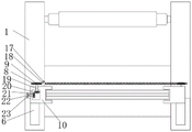
FIG. 1 is a schematic sectional elevation view of the structure of the present invention;
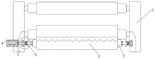
FIG. 2 is a left side view of the structure of the present invention;
FIG. 3 is a schematic cross-sectional front view of an interconnect plate according to the present invention;
FIG. 4 is a schematic top cross-sectional view of the structure of the present invention;
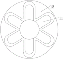
FIG. 5 is a schematic left side sectional view of the first connecting block and the first connecting seat of the present invention;
FIG. 6 is an enlarged view of the structure at A in FIG. 1 according to the present invention;
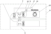
FIG. 7 is an enlarged view of the structure of FIG. 2 of the present invention at D;
FIG. 8 is an enlarged view of the structure of FIG. 7 at B in accordance with the present invention;
fig. 9 is an enlarged view of the structure at C in fig. 7 according to the present invention.
In the figure: 1. a support pillar; 2. a material receiving roller; 3. a cloth body; 4. a servo motor; 5. a first support leg; 6. an inner connection plate; 7. a first sliding groove; 8. a drive chain; 9. a driving wheel; 10. a first support block; 11. a first connection block; 12. a first connecting seat; 13. a first spring; 14. a first card cavity; 15. a second connecting block; 16. a first connecting plate; 17. a first fixed block; 18. a first fixed column; 19. a first drive lever; 20. an inner connecting cavity; 21. a bevel gear; 22. a second transmission rod; 23. a belt pulley; 24. a first motor; 25. a second connecting seat; 26. a cleaning brush; 27. cleaning the hook; 28. a first receiving block; 29. a second spring; 30. a second card cavity; 31. a second fixture block; 32. an inner bearing block; 33. a first ejector rod; 34. a first card slot; 35. a guide seat.
Detailed Description
The technical solutions in the embodiments of the present invention will be clearly and completely described below with reference to the drawings in the embodiments of the present invention, and it is obvious that the described embodiments are only a part of the embodiments of the present invention, and not all of the embodiments. All other embodiments, which can be derived by a person skilled in the art from the embodiments given herein without making any creative effort, shall fall within the protection scope of the present invention.
Referring to fig. 1-9, an embodiment of the present invention is shown: a cloth winding device with a dust removal structure for spinning comprises a support column 1, a material receiving roller 2, a servo motor 4, a first support leg 5 and an inner connecting plate 6, wherein the front surface of the support column 1 is connected with the inner connecting plate 6, the top end surface of the inner connecting plate 6 is connected with a first support block 10, the top end surface of the first support block 10 is provided with a first sliding groove 7, the inside of the first support block 10 is provided with an inner connecting cavity 20, the inside of the inner connecting cavity 20 is penetrated with a second transmission rod 22, one side of the second transmission rod 22 is connected with a bevel gear 21, the other side of the second transmission rod 22 is provided with a belt pulley 23, the surface of the belt pulley 23 is connected with the surface of the servo motor 4 through a belt, the surface of the bevel gear 21 is engaged with another group of bevel gears 21, one side of the other group of bevel gears 21 is connected with a first transmission rod 19, the top end of the first transmission rod 19 is connected with a transmission wheel 9, and the surface of drive wheel 9 is connected with driving chain 8, the surface of driving chain 8 is connected with first fixed column 18, and the surface of first fixed column 18 is connected with first fixed block 17, the inside shape size of first fixed block 17 is the same with the surface shape size of first fixed column 18, first fixed block 17 cup joints the surface at first fixed column 18, the same shape size enables that first fixed block 17 and first fixed column 18 are connected inseparabler, conveniently make first fixed column 18 pull first fixed block 17.
The surface of first fixed block 17 has cup jointed guide holder 35, and the inside shape size of first sliding tray 7 is the same with the bottom surface shape size of guide holder 35, and guide holder 35 inserts the inside of establishing at first sliding tray 7, and guide holder 35 and first sliding tray 7 constitute slidingtype structure, effectively reduce guide holder 35 through constituting the slidingtype structure and carry out produced rocking when sliding along the inside of first sliding tray 7, increase the stability of guide holder 35 when sliding.
One side bottom of first fixed block 17 is connected with first motor 24, and the bottom of first motor 24 is connected with cleaning brush 26, one side surface of first supporting block 10 is connected with interior supporting block 32, and the inside of interior supporting block 32 is inserted and is equipped with first ejector pin 33, the inner wall of interior supporting block 32 is connected with first draw-in groove 34, and the inside of first draw-in groove 34 is inserted and is equipped with second fixture block 31, the inside shape size of second fixture block 31 is the same with the surface shape size of first draw-in groove 34, second fixture block 31 is inserted and is established in the inside of first draw-in groove 34, the same shape size enables that second fixture block 31 and first draw-in groove 34 block inseparabler, reduce the possibility that the production pine takes off.
One side of the second latch 31 is inserted into the second latch cavity 30, the inner wall of the second latch cavity 30 is connected with the second spring 29, one side of the second spring 29 is connected to the inner wall of the second latch cavity 30, the other side of the second spring 29 is connected to the surface of the second latch 31, the second spring 29, the second latch cavity 30 and the second latch 31 form an elastic structure, and the second latch 31 can be automatically clamped with the first latch groove 34 by forming the elastic structure.
Second card chamber 30 is seted up in the inside of first receiving block 28, and one side surface of first receiving block 28 is connected with second connecting seat 25, and the inside first connecting plate 16 that is equipped with of inserting in top of second connecting seat 25, the draw-in groove has been seted up on the top of second connecting seat 25, and the bottom surface of first connecting plate 16 is connected with the fixture block, first connecting plate 16 is inserted and is established in the inside of second connecting seat 25, through making first connecting plate 16 insert and establish the inside of second connecting seat 25, can conveniently fix first connecting plate 16.
The bottom of first connecting plate 16 is connected with clean hook 27, the front of interior connecting plate 6 is connected with first supporting leg 5, and a side surface of first supporting leg 5 is connected with servo motor 4, one side of servo motor 4 is connected with first connecting seat 12, and the inside of first connecting seat 12 is inserted and is equipped with first connecting block 11, the surface shape size of first connecting block 11 is the same with the inside shape size of first connecting seat 12, first connecting block 11 is inserted and is established the inside of first connecting seat 12, the same shape size enables that first connecting block 11 and first connecting seat 12 are connected inseparabler, the reduction produces the possibility that the pine takes off.
First spring 13 has been seted up to first connecting block 11's inside, and one side of first spring 13 is connected with second connecting block 15, and the inner wall at first card chamber 14 is connected to one side of first spring 13, and the opposite side of first spring 13 is connected on the surface of second connecting block 15, and first spring 13, first card chamber 14 and second connecting block 15 constitute elastic construction, can conveniently make first connecting block 11 automatic and first connecting seat 12 carry out the block through constituting elastic construction.
The second connecting block 15 is inserted in the first clamping cavity 14, the surface shape and size of the second connecting block 15 are the same as the internal shape and size of the first clamping cavity 14, the second connecting block 15 is inserted in the first clamping cavity 14, the first clamping cavity 14 and the second connecting block 15 form a sliding type structure, and the first clamping cavity 14 can be conveniently enabled not to shake when the surface of the second connecting block 15 slides by forming the sliding type structure.
First card chamber 14 is seted up in the inside of first connecting block 11, and one side of second connecting block 15 is connected with receipts material roller 2, and the surface winding of receiving material roller 2 has cloth body 3.
The working principle is as follows: when the material receiving roller is in operation, the first connecting block 11 on one side of the material receiving roller 2 can be firstly held, then the first connecting block 11 is pulled to one side of the material receiving roller 2, the first connecting block 11 moves along the surface of the second connecting block 15, the first spring 13 in the first connecting block 11 is in a force-storing compression state, at the moment, the first connecting block 11 can be inserted in the first connecting seat 12, the first connecting block 11 is clamped with the inside of the first connecting seat 12 through the elastic force of the first spring 13, so that the material receiving roller 2 can be fixed, then the servo motor 4 starts to operate through an external power supply, the belt pulley 23 can rotate through the operation of the servo motor 4, at the moment, the belt pulley 23 of the belt transmission can drive the second transmission rod 22 to rotate together, at the moment, the second transmission rod 22 can drive the conical gear 21 to rotate, the engagement between the two sets of bevel gears 21 can make the other set of bevel gears 21 drive the first transmission rod 19 to rotate, and further can make the first transmission rod 19 drive the transmission wheel 9 to rotate, at this time, the transmission chain 8 wound on the surface of the transmission wheel 9 will move, and the first fixing column 18 fixed on the surface of the transmission chain 8 can move together through the movement of the transmission chain 8, at this time, the first fixing block 17 can be driven by the first fixing column 18 to move, and through the guidance of the guiding seat 35, the first fixing block 17 will reciprocate along the surface of the transmission chain 8, at this time, the first motor 24 can be operated again through the external power supply, and the cleaning brush 26 can be rotated through the operation of the first motor 24, at this time, the cleaning brush 26 will hang and brush the fluff adhered on the surface of the cloth body 3, so that the fluff is in a bulk shape, the fluff left on the surface of the cloth body 3 is caught by the brush hook at the bottom end of the cleaning hook 27, so as to prevent the fluff from remaining on the surface of the cloth body 3, after the catching is completed, more fluff will remain on the surface of the cleaning hook 27, at this time, the first push rod 33 can be manually held, the first push rod 33 is pressed to push the second fixture block 31 inserted in the first clamping groove 34 out by the first push rod 33, so that the second fixture block 31 is gradually accommodated in the second clamping cavity 30, at this time, the second fixture block 31 pushed out from the first clamping groove 34 is gradually accommodated in the second clamping cavity 30, and the second spring 29 located in the second fixture block 31 is also in a power storage compression state, at this time, the first clamping groove 34 and the second fixture block 31 will not be clamped any more, and then the second connecting seat 25 can be taken down from the inner accommodating block 32, so as to clean the fluff left on the bottom end surface of the cleaning hook 27, so that the cleaning machine can be always kept in a better cleaning state.
It will be evident to those skilled in the art that the invention is not limited to the details of the foregoing illustrative embodiments, and that the present invention may be embodied in other specific forms without departing from the spirit or essential attributes thereof. The present embodiments are therefore to be considered in all respects as illustrative and not restrictive, the scope of the invention being indicated by the appended claims rather than by the foregoing description, and all changes which come within the meaning and range of equivalency of the claims are therefore intended to be embraced therein. Any reference sign in a claim should not be construed as limiting the claim concerned.
Claims (9)

1.一种纺织用具有除尘结构的布料收卷装置,包括支撑柱(1)、收料辊(2)、伺服电机(4)、第一支撑腿(5)和内连接板(6),其特征在于:所述支撑柱(1)的正面连接有内连接板(6),且内连接板(6)的顶端表面连接有第一支撑块(10),且第一支撑块(10)的顶端表面开设有第一滑动槽(7),所述第一支撑块(10)的内部开设有内连接腔(20),且内连接腔(20)的内部贯穿有第二传动杆(22),所述第二传动杆(22)的一侧连接有锥形齿轮(21),所述第二传动杆(22)的另一侧连接有皮带轮(23),所述皮带轮(23)的表面通过皮带连接伺服电机(4),所述锥形齿轮(21)的表面啮合有另一组所述锥形齿轮(21),且另一组所述锥形齿轮(21)的一侧连接有第一传动杆(19),所述第一传动杆(19)的顶端连接有传动轮(9),且传动轮(9)的表面连接有传动链(8),所述传动链(8)的表面连接有第一固定柱(18),且第一固定柱(18)的表面连接有第一固定块(17),且第一固定块(17)的表面套接有引导座(35),所述第一固定块(17)的一侧底端连接有第一电机(24),且第一电机(24)的底端连接有清洁刷(26),所述第一支撑块(10)的一侧表面连接有内承接块(32),且内承接块(32)的内部插设有第一顶杆(33),所述内承接块(32)的内壁连接有第一卡槽(34),且第一卡槽(34)的内部插设有第二卡块(31),所述第二卡块(31)的一侧插设在第二卡腔(30)的内部,且第二卡腔(30)的内壁连接有第二弹簧(29),所述第二卡腔(30)开设在第一承接块(28)的内部,且第一承接块(28)的一侧表面连接有第二连接座(25),且第二连接座(25)的顶端内部插设有第一连接板(16),所述第一连接板(16)的底端连接有清洁钩(27),所述内连接板(6)的正面连接有第一支撑腿(5),且第一支撑腿(5)的一侧表面连接有伺服电机(4),所述伺服电机(4)的一侧连接有第一连接座(12),且第一连接座(12)的内部插设有第一连接块(11),所述第一连接块(11)的内部开设有第一弹簧(13),且第一弹簧(13)的一侧连接有第二连接块(15),所述第二连接块(15)插设在第一卡腔(14)的内部,所述第一卡腔(14)开设在第一连接块(11)的内部,所述第二连接块(15)的一侧连接有收料辊(2),且收料辊(2)的表面缠绕有布料本体(3);在进行工作时首先握持收料辊一侧的第一连接块,然后向收料辊的一侧拉动第一连接块,使第一连接块沿着第二连接块的表面进行移动,并且使第一连接块内部的第一弹簧呈现蓄力压缩状态,此时可将第一连接块插设在第一连接座的内部,使第一连接块通过第一弹簧的弹力作用和第一连接座的内部进行卡合,从而使收料辊进行固定,随后通过外接电源使伺服电机开始进行工作,并且通过伺服电机的工作通过皮带传动使皮带轮进行旋转,此时,通过皮带传动的皮带轮将会带动第二传动杆一同进行旋转,此时第二传动杆将会带动锥形齿轮进行旋转,而两组锥形齿轮之间的啮合,使另一组锥形齿轮带动第一传动杆进行旋转,进而可以使第一传动杆带动传动轮进行旋转,此时,缠绕在传动轮表面的传动链将会进行移动,而通过传动链的移动使固定在传动链表面的第一固定柱一同进行移动,此时通过第一固定柱带动第一固定块进行移动,并且通过引导座的引导,第一固定块将会沿着传动链的表面做往复运动,此时再次通过外接电源使第一电机进行工作,并且通过第一电机的工作使清洁刷进行旋转,此时,清洁刷将会对粘附在布料本体表面的绒毛进行挂刷,使绒毛呈现团状,残留在布料本体的表面,此时位于布料本体表面的绒毛将会被清洁钩底端的刷钩勾取,避免绒毛残留在布料本体的表面,当钩取完毕后,清洁钩的表面将会残留较多的绒毛,此时手动握持第一顶杆,按压第一顶杆使第一顶杆将插设在第一卡槽内部的第二卡块推出,使第二卡块逐渐收纳在第二卡腔的内部,此时,被从第一卡槽内部推出的第二卡块将会逐渐收纳在第二卡腔的内部,而位于第二卡块侧的第二弹簧也会呈现蓄力压缩状态,此时第一卡槽和第二卡块将不再进行卡合,然后将第二连接座从内承接块的内部取下,对清洁钩底端表面残留的绒毛进行清理,使其始终能保持在较佳的清洁状态。1. A cloth winding device with a dust-removing structure for textiles, comprising a support column (1), a take-up roller (2), a servo motor (4), a first support leg (5) and an inner connecting plate (6), It is characterized in that: the front surface of the support column (1) is connected with an inner connecting plate (6), and the top surface of the inner connecting plate (6) is connected with a first support block (10), and the first support block (10) A first sliding groove (7) is opened on the top surface of the first support block (10), an inner connection cavity (20) is opened inside the first support block (10), and a second transmission rod (22) runs through the inner connection cavity (20). ), a bevel gear (21) is connected to one side of the second transmission rod (22), and a pulley (23) is connected to the other side of the second transmission rod (22). The surface is connected to the servo motor (4) through a belt, the surface of the bevel gear (21) is meshed with another group of the bevel gears (21), and one side of the other group of the bevel gears (21) is connected There is a first transmission rod (19), the top of the first transmission rod (19) is connected with a transmission wheel (9), and the surface of the transmission wheel (9) is connected with a transmission chain (8), the transmission chain (8) ) is connected to the surface of the first fixing column (18), and the surface of the first fixing column (18) is connected to the first fixing block (17), and the surface of the first fixing block (17) is sleeved with a guide seat (35). ), a first motor (24) is connected to the bottom end of one side of the first fixing block (17), and a cleaning brush (26) is connected to the bottom end of the first motor (24), and the first support block ( 10) An inner receiving block (32) is connected to one side surface of the inner receiving block (32), and a first ejector rod (33) is inserted inside the inner receiving block (32), and the inner wall of the inner receiving block (32) is connected with a first card a slot (34), and a second clamping block (31) is inserted inside the first clamping slot (34), and one side of the second clamping block (31) is inserted inside the second clamping cavity (30) , and the inner wall of the second clamping cavity (30) is connected with a second spring (29), the second clamping cavity (30) is opened inside the first receiving block (28), and the first receiving block (28) A second connecting seat (25) is connected to one side surface, and a first connecting plate (16) is inserted inside the top end of the second connecting seat (25), and the bottom end of the first connecting plate (16) is connected with a cleaning The hook (27), the front surface of the inner connecting plate (6) is connected with the first support leg (5), and the side surface of the first support leg (5) is connected with the servo motor (4), the servo motor ( 4) A first connecting seat (12) is connected to one side, and a first connecting block (11) is inserted in the inside of the first connecting seat (12), and a first connecting block (11) is opened inside the first connecting block (11). A spring (13), and one side of the first spring (13) is connected with a second connecting block (15), the second connecting block (15) is inserted inside the first card cavity (14), the The first card cavity (14) is opened inside the first connecting block (11), the second connecting block (15) is connected with a receiving roller (2) on one side, and the surface of the receiving roller (2) is wound around There is a cloth body (3); when working, firstly hold the first connecting block on the side of the receiving roller, and then pull the first connecting block to the side of the receiving roller, so that the first connecting block is along the second connecting block The surface of the first connecting block moves, and the first spring inside the first connecting block is in a state of accumulating force and compression. At this time, the first connecting block can be inserted into the inside of the first connecting seat, so that the first connecting block passes through the force of the first spring. The elastic force is engaged with the inside of the first connecting seat, so that the receiving roller is fixed, and then the servo motor starts to work through the external power supply, and the pulley is rotated through the belt drive through the work of the servo motor. The pulley of the belt drive will drive the second transmission rod to rotate together, at this time the second transmission rod will drive the bevel gear to rotate, and the meshing between the two sets of bevel gears makes the other set of bevel gears drive the first bevel gear. A transmission rod rotates, so that the first transmission rod can drive the transmission wheel to rotate. At this time, the transmission chain wound on the surface of the transmission wheel will move, and the first transmission chain fixed on the surface of the transmission chain will move through the movement of the transmission chain. The fixed column moves together. At this time, the first fixed block is driven by the first fixed column to move, and guided by the guide seat, the first fixed block will reciprocate along the surface of the transmission chain. At this time, through the external power supply again Make the first motor work, and make the cleaning brush rotate through the operation of the first motor. At this time, the cleaning brush will brush the fluff adhering to the surface of the cloth body, so that the fluff is in a lump shape and remains on the cloth body. At this time, the fluff on the surface of the cloth body will be hooked by the brush hook at the bottom of the cleaning hook to avoid the fluff remaining on the surface of the cloth body. At this time, manually hold the first ejector rod, press the first ejector rod, so that the first ejector rod pushes out the second block inserted in the first card slot, so that the second block is gradually accommodated in the second card cavity. , at this time, the second block pushed out from the first card slot will be gradually accommodated in the second card cavity, and the second spring on the side of the second block will also be in a state of accumulating force and compression. The first card slot and the second card block will no longer be engaged, and then the second connecting seat is removed from the inside of the inner receiving block, and the residual fluff on the bottom surface of the cleaning hook is cleaned to keep it at a relatively high level. best clean condition. 2.根据权利要求1所述的一种纺织用具有除尘结构的布料收卷装置,其特征在于:所述第一滑动槽(7)的内部形状大小和引导座(35)的底端表面形状大小相同,且引导座(35)插设在第一滑动槽(7)的内部,所述引导座(35)和第一滑动槽(7)组成滑动式结构。2 . The cloth rewinding device with a dust-removing structure for textiles according to claim 1 , wherein: the inner shape and size of the first sliding groove ( 7 ) and the bottom surface shape of the guide seat ( 35 ) are: 2 . The size of the guide seat (35) is the same, and the guide seat (35) is inserted inside the first sliding groove (7). The guide seat (35) and the first sliding groove (7) form a sliding structure. 3.根据权利要求1所述的一种纺织用具有除尘结构的布料收卷装置,其特征在于:所述第一连接块(11)的表面形状大小和第一连接座(12)的内部形状大小相同,所述第一连接块(11)插设在第一连接座(12)的内部。3. A cloth winding device with a dust-removing structure for textile use according to claim 1, characterized in that: the surface shape and size of the first connecting block (11) and the internal shape of the first connecting seat (12) The sizes are the same, and the first connecting block (11) is inserted inside the first connecting seat (12). 4.根据权利要求1所述的一种纺织用具有除尘结构的布料收卷装置,其特征在于:所述第一弹簧(13)的一侧连接在第一卡腔(14)的内壁,且第一弹簧(13)的另一侧连接在第二连接块(15)的表面,所述第一弹簧(13)、第一卡腔(14)和第二连接块(15)组成弹性结构。4. A cloth winding device with a dust-removing structure for textile use according to claim 1, characterized in that: one side of the first spring (13) is connected to the inner wall of the first card cavity (14), and The other side of the first spring (13) is connected to the surface of the second connecting block (15), and the first spring (13), the first clamping cavity (14) and the second connecting block (15) form an elastic structure. 5.根据权利要求1所述的一种纺织用具有除尘结构的布料收卷装置,其特征在于:所述第二连接块(15)的表面形状大小和第一卡腔(14)的内部形状大小相同,所述第二连接块(15)插设在第一卡腔(14)的内部,所述第一卡腔(14)和第二连接块(15)组成滑动式结构。5. A cloth winding device with a dust-removing structure for textile use according to claim 1, characterized in that: the surface shape and size of the second connecting block (15) and the internal shape of the first card cavity (14) The sizes are the same, the second connecting block (15) is inserted inside the first card cavity (14), and the first card cavity (14) and the second connecting block (15) form a sliding structure. 6.根据权利要求1所述的一种纺织用具有除尘结构的布料收卷装置,其特征在于:所述第一固定块(17)的内部形状大小和第一固定柱(18)的表面形状大小相同,所述第一固定块(17)套接在第一固定柱(18)的表面。6. A cloth winding device with a dust-removing structure for textile use according to claim 1, characterized in that: the internal shape and size of the first fixing block (17) and the surface shape of the first fixing column (18) The sizes are the same, and the first fixing block (17) is sleeved on the surface of the first fixing column (18). 7.根据权利要求1所述的一种纺织用具有除尘结构的布料收卷装置,其特征在于:所述第二连接座(25)的顶端开设有卡槽,且第一连接板(16)的底端表面连接有卡块,所述第一连接板(16)插设在第二连接座(25)的内部。7. A cloth winding device with a dust-removing structure for textile use according to claim 1, characterized in that: the top end of the second connecting seat (25) is provided with a slot, and the first connecting plate (16) The bottom surface of the base is connected with a clamping block, and the first connecting plate (16) is inserted inside the second connecting seat (25). 8.根据权利要求1所述的一种纺织用具有除尘结构的布料收卷装置,其特征在于:所述第二弹簧(29)的一侧连接在第二卡腔(30)的内壁,且第二弹簧(29)的另一侧连接在第二卡块(31)的表面,所述第二弹簧(29)、第二卡腔(30)和第二卡块(31)组成弹性结构。8. A cloth winding device with a dust-removing structure for textile use according to claim 1, characterized in that: one side of the second spring (29) is connected to the inner wall of the second clamping cavity (30), and The other side of the second spring (29) is connected to the surface of the second clamping block (31), and the second spring (29), the second clamping cavity (30) and the second clamping block (31) form an elastic structure. 9.根据权利要求1所述的一种纺织用具有除尘结构的布料收卷装置,其特征在于:所述第二卡块(31)的内部形状大小和第一卡槽(34)的表面形状大小相同,所述第二卡块(31)插设在第一卡槽(34)的内部。9 . The cloth winding device with dust removal structure for textile use according to claim 1 , characterized in that: the internal shape and size of the second clamping block ( 31 ) and the surface shape of the first clamping groove ( 34 ) The sizes are the same, and the second clamping block (31) is inserted inside the first clamping slot (34).
CN202010369949.4A 2020-05-03 2020-05-03 Cloth coiling mechanism with dust removal structure for weaving Active CN111532834B (en)

Priority Applications (1)

Application Number Priority Date Filing Date Title
CN202010369949.4A CN111532834B (en) 2020-05-03 2020-05-03 Cloth coiling mechanism with dust removal structure for weaving

Applications Claiming Priority (1)

Application Number Priority Date Filing Date Title
CN202010369949.4A CN111532834B (en) 2020-05-03 2020-05-03 Cloth coiling mechanism with dust removal structure for weaving

Publications (2)

Publication Number Publication Date
CN111532834A CN111532834A (en) 2020-08-14
CN111532834B true CN111532834B (en) 2022-06-10

Family

ID=71971569

Family Applications (1)

Application Number Title Priority Date Filing Date
CN202010369949.4A Active CN111532834B (en) 2020-05-03 2020-05-03 Cloth coiling mechanism with dust removal structure for weaving

Country Status (1)

Country Link
CN (1) CN111532834B (en)

Families Citing this family (1)

* Cited by examiner, † Cited by third party
Publication number Priority date Publication date Assignee Title
CN116986365B (en) * 2023-06-30 2025-09-09 杭州青云新材料股份有限公司 Polyurethane yarn bonding equipment and method for preventing irregular bulge in unreeling

Family Cites Families (8)

* Cited by examiner, † Cited by third party
Publication number Priority date Publication date Assignee Title
AT504380B1 (en) * 2006-11-06 2008-10-15 Schilling Franz DEVICE FOR CLEANING FOOT MATS
CN105063935A (en) * 2015-07-23 2015-11-18 陈信发 Wrinkle resistance and surface processing device of textile fabrics
CN105908471A (en) * 2016-05-27 2016-08-31 苏州舒而适纺织新材料科技有限公司 Dust exhausting device for textiles
CN207861526U (en) * 2018-02-05 2018-09-14 福建永丰针纺有限公司 A kind of cloth jacquard attachment
CN110528251A (en) * 2018-05-23 2019-12-03 浙江省现代纺织工业研究院 A kind of dedusting defeathering ball device of woolens fabric
CN109230785B (en) * 2018-07-20 2020-07-28 宁波高新区盛文途纺织品有限公司 A hair ball removing device for wool cloth
CN110656481A (en) * 2019-11-07 2020-01-07 湖北阳新远东麻业有限公司 Cleaning device is used in oxford production
CN110999821A (en) * 2019-12-02 2020-04-14 西安沃唯隆控制系统有限公司 Thermostat for PLC control

Also Published As

Publication number Publication date
CN111532834A (en) 2020-08-14

Similar Documents

Publication Publication Date Title
CN213113654U (en) Dust collecting device of textile machine
CN109879099B (en) Hot pressing coiling equipment of non-woven fabrics
CN215478599U (en) Weaving is with weaving cloth rolling machine
CN111532834B (en) Cloth coiling mechanism with dust removal structure for weaving
CN109576969A (en) A kind of dust-extraction unit for Weaving device
CN209871846U (en) Textile apparatus with dust removal function
CN112122252A (en) Double-sided dust removal system of textile machine and dust removal method thereof
CN114960067A (en) Cloth humidification processing device of polyester fiber cloth production usefulness
JPS58174609A (en) Apparatus for collecting cocoon and removing floss
CN209291721U (en) Material collecting device is used in a kind of production of textile product
CN112122898B (en) Household small-sized hammer manufacturing machine
CN222454102U (en) Automatic cleaning mechanism for miscellaneous threads of computerized silk winding machine
CN221822433U (en) An efficient automatic yarn doffing device
CN221192681U (en) Cloth surface dust collector for clothing weaving
CN211171331U (en) Spinning machine with high-efficient dust absorption function
CN221501548U (en) Deburring device for textile production
CN118516840B (en) Dust removal equipment for textile products
CN221855087U (en) A beating device for brush bristles
CN110467054B (en) A thread clamping and cutting device for cotton sewing thread
CN112518140A (en) Cutting equipment for weaving
CN222159202U (en) Cloth winding device with flock collecting mechanism
CN215051506U (en) Household towel surface fiber adsorption device
CN213833840U (en) A high-efficiency pulling and winding device for warp knitted fabrics
CN223113721U (en) Thread end collecting device for textile production
CN222920593U (en) A new type of slitting device for plastic flexible packaging production

Legal Events

Date Code Title Description
PB01 Publication
PB01 Publication
SE01 Entry into force of request for substantive examination
TA01 Transfer of patent application right

Effective date of registration: 20220512

Address after: 251400 Jibei Development Zone, Jiyang District, Jinan City, Shandong Province

Applicant after: SHANDONG TAROKO WEAVING & DYEING INDUSTRY Co.,Ltd.

Address before: 710072 No. 127 Youyi West Road, Shaanxi, Xi'an

Applicant before: Duan Peirong

TA01 Transfer of patent application right
GR01 Patent grant
GR01 Patent grant
PE01 Entry into force of the registration of the contract for pledge of patent right

Denomination of invention: A fabric winding device with dust removal structure for textile use

Effective date of registration: 20230410

Granted publication date: 20220610

Pledgee: Qilu bank Limited by Share Ltd. Ji'nan Jiyang branch

Pledgor: SHANDONG TAROKO WEAVING & DYEING INDUSTRY Co.,Ltd.

Registration number: Y2023980037685

PE01 Entry into force of the registration of the contract for pledge of patent right
PC01 Cancellation of the registration of the contract for pledge of patent right

Granted publication date: 20220610

Pledgee: Qilu bank Limited by Share Ltd. Ji'nan Jiyang branch

Pledgor: SHANDONG TAROKO WEAVING & DYEING INDUSTRY Co.,Ltd.

Registration number: Y2023980037685