CN111514439A - Drainage tube daily indwelling fixing device - Google Patents
Drainage tube daily indwelling fixing device Download PDFInfo
- Publication number
- CN111514439A CN111514439A CN202010354938.9A CN202010354938A CN111514439A CN 111514439 A CN111514439 A CN 111514439A CN 202010354938 A CN202010354938 A CN 202010354938A CN 111514439 A CN111514439 A CN 111514439A
- Authority
- CN
- China
- Prior art keywords
- drainage tube
- drawer
- daily
- indwelling
- fixing
- Prior art date
- Legal status (The legal status is an assumption and is not a legal conclusion. Google has not performed a legal analysis and makes no representation as to the accuracy of the status listed.)
- Pending
Links
- 238000009434 installation Methods 0.000 claims abstract description 29
- 238000001125 extrusion Methods 0.000 claims abstract description 27
- 238000012423 maintenance Methods 0.000 claims description 18
- 238000005192 partition Methods 0.000 claims description 9
- 230000000694 effects Effects 0.000 description 12
- 230000017525 heat dissipation Effects 0.000 description 10
- 238000004659 sterilization and disinfection Methods 0.000 description 3
- 238000000034 method Methods 0.000 description 2
- 238000007789 sealing Methods 0.000 description 2
- 241000894006 Bacteria Species 0.000 description 1
- 206010067268 Post procedural infection Diseases 0.000 description 1
- 206010044565 Tremor Diseases 0.000 description 1
- 230000002421 anti-septic effect Effects 0.000 description 1
- 230000009286 beneficial effect Effects 0.000 description 1
- 239000008280 blood Substances 0.000 description 1
- 210000004369 blood Anatomy 0.000 description 1
- 230000007547 defect Effects 0.000 description 1
- 238000001035 drying Methods 0.000 description 1
- 238000005516 engineering process Methods 0.000 description 1
- 230000003760 hair shine Effects 0.000 description 1
- 239000007788 liquid Substances 0.000 description 1
- 230000001737 promoting effect Effects 0.000 description 1
- 230000001954 sterilising effect Effects 0.000 description 1
- 238000001356 surgical procedure Methods 0.000 description 1
- 230000007306 turnover Effects 0.000 description 1
- 230000029663 wound healing Effects 0.000 description 1
Images




Classifications
-
- A—HUMAN NECESSITIES
- A61—MEDICAL OR VETERINARY SCIENCE; HYGIENE
- A61M—DEVICES FOR INTRODUCING MEDIA INTO, OR ONTO, THE BODY; DEVICES FOR TRANSDUCING BODY MEDIA OR FOR TAKING MEDIA FROM THE BODY; DEVICES FOR PRODUCING OR ENDING SLEEP OR STUPOR
- A61M25/00—Catheters; Hollow probes
- A61M25/01—Introducing, guiding, advancing, emplacing or holding catheters
- A61M25/02—Holding devices, e.g. on the body
-
- A—HUMAN NECESSITIES
- A61—MEDICAL OR VETERINARY SCIENCE; HYGIENE
- A61L—METHODS OR APPARATUS FOR STERILISING MATERIALS OR OBJECTS IN GENERAL; DISINFECTION, STERILISATION OR DEODORISATION OF AIR; CHEMICAL ASPECTS OF BANDAGES, DRESSINGS, ABSORBENT PADS OR SURGICAL ARTICLES; MATERIALS FOR BANDAGES, DRESSINGS, ABSORBENT PADS OR SURGICAL ARTICLES
- A61L2/00—Methods or apparatus for disinfecting or sterilising materials or objects other than foodstuffs or contact lenses; Accessories therefor
- A61L2/02—Methods or apparatus for disinfecting or sterilising materials or objects other than foodstuffs or contact lenses; Accessories therefor using physical phenomena
- A61L2/08—Radiation
- A61L2/10—Ultraviolet radiation
-
- H—ELECTRICITY
- H05—ELECTRIC TECHNIQUES NOT OTHERWISE PROVIDED FOR
- H05K—PRINTED CIRCUITS; CASINGS OR CONSTRUCTIONAL DETAILS OF ELECTRIC APPARATUS; MANUFACTURE OF ASSEMBLAGES OF ELECTRICAL COMPONENTS
- H05K5/00—Casings, cabinets or drawers for electric apparatus
- H05K5/02—Details
- H05K5/0213—Venting apertures; Constructional details thereof
-
- H—ELECTRICITY
- H05—ELECTRIC TECHNIQUES NOT OTHERWISE PROVIDED FOR
- H05K—PRINTED CIRCUITS; CASINGS OR CONSTRUCTIONAL DETAILS OF ELECTRIC APPARATUS; MANUFACTURE OF ASSEMBLAGES OF ELECTRICAL COMPONENTS
- H05K7/00—Constructional details common to different types of electric apparatus
- H05K7/20—Modifications to facilitate cooling, ventilating, or heating
- H05K7/20009—Modifications to facilitate cooling, ventilating, or heating using a gaseous coolant in electronic enclosures
- H05K7/20127—Natural convection
-
- A—HUMAN NECESSITIES
- A61—MEDICAL OR VETERINARY SCIENCE; HYGIENE
- A61L—METHODS OR APPARATUS FOR STERILISING MATERIALS OR OBJECTS IN GENERAL; DISINFECTION, STERILISATION OR DEODORISATION OF AIR; CHEMICAL ASPECTS OF BANDAGES, DRESSINGS, ABSORBENT PADS OR SURGICAL ARTICLES; MATERIALS FOR BANDAGES, DRESSINGS, ABSORBENT PADS OR SURGICAL ARTICLES
- A61L2202/00—Aspects relating to methods or apparatus for disinfecting or sterilising materials or objects
- A61L2202/20—Targets to be treated
- A61L2202/24—Medical instruments, e.g. endoscopes, catheters, sharps
-
- A—HUMAN NECESSITIES
- A61—MEDICAL OR VETERINARY SCIENCE; HYGIENE
- A61M—DEVICES FOR INTRODUCING MEDIA INTO, OR ONTO, THE BODY; DEVICES FOR TRANSDUCING BODY MEDIA OR FOR TAKING MEDIA FROM THE BODY; DEVICES FOR PRODUCING OR ENDING SLEEP OR STUPOR
- A61M25/00—Catheters; Hollow probes
- A61M25/01—Introducing, guiding, advancing, emplacing or holding catheters
- A61M25/02—Holding devices, e.g. on the body
- A61M2025/028—Holding devices, e.g. on the body having a mainly rigid support structure
Landscapes
- Health & Medical Sciences (AREA)
- Engineering & Computer Science (AREA)
- Microelectronics & Electronic Packaging (AREA)
- Life Sciences & Earth Sciences (AREA)
- Animal Behavior & Ethology (AREA)
- General Health & Medical Sciences (AREA)
- Veterinary Medicine (AREA)
- Public Health (AREA)
- Anesthesiology (AREA)
- Biomedical Technology (AREA)
- Heart & Thoracic Surgery (AREA)
- Hematology (AREA)
- Physics & Mathematics (AREA)
- Thermal Sciences (AREA)
- Pulmonology (AREA)
- Biophysics (AREA)
- Epidemiology (AREA)
- Accommodation For Nursing Or Treatment Tables (AREA)
Abstract
The invention discloses a daily indwelling and fixing device of a drainage tube, which comprises a box body, wherein two installation blocks are arranged inside the box body, slide blocks are arranged on one opposite sides of the two installation blocks, a drawer is arranged between the two slide blocks, a driving mechanism is fixedly arranged inside the drawer, the drainage tube is accommodated on a roller through the rotation of the roller through the matching use of a storage battery, the driving mechanism, a driving gear, a driven gear, a second rotating shaft, a baffle plate and the roller, the storage battery provides kinetic energy for the driving mechanism through electric energy, the driving mechanism drives the driving gear to rotate, the driving gear drives the driven gear to rotate through meshing connection, the driven gear drives the baffle plate and the roller to rotate through the second rotating shaft, an electric push rod mechanism pushes an extrusion plate to clamp the drainage tube, sponge wraps the drainage tube to prevent the drainage tube from being damaged, the drainage tube is orderly arranged and is convenient to take, so that the practicability of the device is improved.
Description
Technical Field
The invention relates to the technical field of medical instruments, in particular to a daily indwelling fixing device for a drainage tube.
Background
The drainage tube is used for clinical surgery drainage, and guides pus, blood and liquid accumulated in human tissues or body cavities to the outside of the body, thereby preventing postoperative infection and promoting wound healing.
Along with the drainage tube uses the back, place the antiseptic solution with the drainage tube in the disinfect box and soak usually, and people all adopt the mode of drying naturally after the drainage tube disinfection, but at the in-process that dries naturally, the bacterium in the air can be stained with and attach on the surface of drainage tube, has reduced the disinfection effect of drainage tube, and has to discharge in a jumble, take inconvenient phenomenon, and do not possess other functions, lead to greatly reducing of its practicality, so not only increased medical staff's work burden, but also reduced work efficiency.
Therefore, in view of the above, the present invention provides a drainage tube daily indwelling fixing device, which is developed and improved in view of the existing structure and defects, so as to achieve the purpose of higher practical value.
Disclosure of Invention
The invention aims to solve the problems in the background technology and provides a drainage tube daily indwelling fixing device.
A daily indwelling fixing device for a drainage tube comprises a box body, wherein two installation blocks are installed inside the box body, a sliding block is installed on one side, opposite to the two installation blocks, of each installation block, a drawer is installed between the two sliding blocks, a driving mechanism is fixedly installed inside the drawer, a first rotating shaft is installed on the left side of the driving mechanism, a driving gear is installed on the left side of the first rotating shaft and is connected with a driven gear through meshing, a second rotating shaft is installed on the left side of the driven gear, a partition plate is installed on the left side of the second rotating shaft and is provided with holes for the second rotating shaft to penetrate through and be connected with two installation parts, two installation parts are internally provided with bearings for connecting the second rotating shaft, a roller is installed on the second rotating shaft and is provided with the drainage tube, and baffles are installed, a fixing opening is formed in one side, facing the roller, of the baffle plate, a first cavity and a second cavity are arranged in the baffle plate, a spring mechanism is arranged on the first cavity, a first extrusion block is arranged at the left end of the spring mechanism, a traction rope is arranged and connected on the right side of the first extrusion block, the traction rope is connected with the second extrusion block through a rope fixing piece, an electric push rod mechanism is fixedly arranged on the inner wall of the drawer, an extrusion plate is fixedly arranged at the shaft end of the electric push rod mechanism, and a sponge is arranged on one side, away from the electric push rod mechanism, of the extrusion plate;
furthermore, a storage battery is arranged in the box body, and the storage battery is arranged to improve the electric energy;
furthermore, the drawer and the sliding block are connected in a sliding fit manner in a sliding groove of the mounting block, the drawer is driven to move outwards by pulling the handle, and the drawer slides in the sliding groove of the mounting block through the sliding block, so that the drawer can freely enter and exit;
furthermore, an installation sheet is installed inside the box body, an ultraviolet lamp tube is installed on the lower side of the installation sheet, the installation sheet is screwed and fixedly installed through installation screws, and threaded holes corresponding to the installation screws are formed in the box body and the installation sheet, so that tight connection is formed between the teeth, the situation that the box body and the ultraviolet lamp tube are installed unstably due to the fact that tight connection cannot be achieved between the teeth is avoided, and installation stability of the ultraviolet lamp tube is improved;
furthermore, a second maintenance door is arranged above the drawer, a lockset mechanism is arranged on the second maintenance door, the second maintenance door and the partition plate separate the driving mechanism, the driving gear and the driven gear, and the driving mechanism, the driving gear and the driven gear are separated from the accommodating mechanism through the arrangement of the partition plate;
furthermore, a handle is arranged on the front surface of the drawer, and the effect of opening the drawer conveniently is achieved by arranging the handle;
furthermore, heat dissipation holes and charging interfaces are formed in the right side of the box body, the heat dissipation holes are long-strip-shaped, a large amount of heat can be generated in the box body due to long-time use of the equipment, and the equipment can be effectively cooled through the heat dissipation holes, so that the heat dissipation performance of the equipment is improved;
furthermore, a first maintenance door is installed on the rear side of the box body, a lock mechanism is installed on the first maintenance door, the first maintenance door is movably connected with the box body through a hinge mechanism, the lock mechanism is an appliance playing a role in sealing and comprises a lock, a key and accessories thereof, the lock mechanism is generally opened through the key, and the safety of equipment is improved through the arrangement of the lock mechanism;
further, the downside setting of box closes soon through the screw thread and installs the supporting seat, the rubber pad is installed to the lower extreme of supporting seat, makes box and desktop separate through the erection bracing seat, has promoted the life of equipment, and there is not flat phenomenon in the desktop, and the supporting seat is established to adjustable to avoid leading to the box unstability because of the desktop is uneven, and the axle head of supporting seat is equipped with the rubber pad, and the rubber pad contacts with the desktop can increase with the frictional force of desktop, can guarantee the stability of equipment effectively to the stability of equipment has been promoted.
The invention has the beneficial effects that:
1. through the battery, actuating mechanism, first rotation axis, the driving gear, driven gear, the second rotation axis, the baffle, the cooperation of cylinder is used, the battery provides actuating mechanism through the electric energy and produces kinetic energy, actuating mechanism drives first rotation axis rotation, first rotation axis drives the driving gear and rotates, the driving gear drives driven gear through the meshing connection and rotates, driven gear drives the second rotation axis and rotates, the second rotation axis drives baffle and cylinder and rotates, the cylinder is accomodate the drainage tube on the cylinder through rotating, electric putter mechanism promotes the stripper plate and presss from both sides the drainage tube tightly, the sponge lives the drainage tube parcel and does not let its damage, it discharges in order to realize the drainage tube, the convenient effect of taking, thereby the practicality of equipment has been promoted.
2. Through the drainage tube, the fixed port, first cavity, the second cavity, first extrusion piece, the second extrusion piece, spring mechanism, the haulage rope, the cooperation of rope mounting is used, when needs are accomodate the drainage tube is fixed, through inserting drainage tube one end from the fixed port, the first extrusion piece in the first cavity of drainage tube extrusion, first extrusion piece backward motion, compress spring mechanism to the state of tightening, the second extrusion piece in the second cavity stimulates the haulage rope and presss from both sides the tight fixing with the drainage tube, thereby the realization is with the stable effect of fixing of drainage tube.
3. Through the cooperation use of battery, ultraviolet fluorescent tube, drawer, cylinder, drainage tube, utilize the cylinder to accomodate the drainage tube through opening the drawer, push back the drawer to initial position again, the battery provides the ultraviolet fluorescent tube through the electric energy and shines the ultraviolet ray, utilizes the ultraviolet ray to disinfect the drainage tube and disinfect to equipment has been promoted and has carried out sterilamp's effect to the drainage tube.
4. Through the cooperation use of handle, drawer, slider, installation piece, through the pulling handle, the handle drives the drawer outwards to move, and the drawer passes through the slider and slides in the spout of installation piece to realize the effect that the drawer business turn over is free.
5. Make box and desktop separate through the erection bracing seat, promoted the life of equipment, and the desktop has uneven phenomenon, and the supporting seat is established to adjustable in order to avoid leading to the box unstability because of the desktop is uneven, and the axle head of supporting seat is equipped with the rubber pad, and the rubber pad contacts with the desktop can increase with the frictional force of desktop, can guarantee the stability of equipment effectively to the stability of equipment has been promoted.
Drawings
FIG. 1 is a cross-sectional view of the structure of the present invention;
FIG. 2 is a schematic view of a drawer configuration of the present invention;
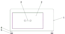
FIG. 3 is a front view of the present invention;
FIG. 4 is a side view of the present invention;
FIG. 5 is a rear view of the present invention;
FIG. 6 is a schematic view of the structure of part A of FIG. 1 according to the present invention;
FIG. 7 is a schematic view of the gear mechanism of the present invention;
fig. 8 is a schematic structural view of the hinge mechanism of the present invention.
In the figure: 1. a box body; 2. a drawer; 3. a handle; 4. a supporting seat; 5. a rubber pad; 6. heat dissipation holes; 7. a charging interface; 8. a first maintenance door; 9. a storage battery; 10. a drive mechanism; 11. a first rotating shaft; 12. a driving gear; 13. a driven gear; 14. a second rotation shaft; 15. mounting screws; 16. mounting a sheet; 17. an ultraviolet lamp tube; 18. a hinge mechanism; 19. a slider; 20. a partition plate; 21. mounting blocks; 22. a mounting member; 23. a baffle plate; 24. a pressing plate; 25. a sponge; 26. a drainage tube; 27. a lock mechanism; 28. repairing the door in a second dimension; 29. an electric push rod mechanism; 30. a second extrusion block; 31. a first extrusion block; 32. a first cavity; 33. a spring mechanism; 34. a rope fixing member; 35. a hauling rope; 36. a second cavity; 37. a drum; 38. and (4) fixing the port.
Detailed Description
The invention is further described below with reference to the accompanying drawings:
example (b):
as shown in figures 1 to 8:
the invention provides a daily indwelling and fixing device of a drainage tube, which comprises a box body 1, wherein two mounting blocks 21 are arranged inside the box body 1, sliding blocks 19 are respectively arranged on one opposite sides of the two mounting blocks 21, a drawer 2 is arranged between the two sliding blocks 19, a handle 3 is arranged on the front surface of the drawer 2, the effect of opening the drawer 2 is realized by mounting the handle 3, the drawer 2 and the sliding blocks 19 are connected in a sliding way of the mounting blocks 21 in a sliding and matching way, the drawer 2 is driven to move outwards by pulling the handle 3, the drawer 2 slides in the sliding way of the mounting blocks 21 through the sliding blocks 19, so that the drawer 2 can freely move in and out, a driving mechanism 10 is fixedly arranged inside the drawer 2, a first rotating shaft 11 is arranged on the left side of the driving mechanism 10, a driving gear 12 is arranged on the left side of the first rotating shaft 11, the driving gear 12 is connected with a, a partition plate 20 is installed on the left side of the second rotating shaft 14, a second maintenance door 28 is installed above the drawer 2, a lock mechanism 27 is installed on the second maintenance door 28, the driving mechanism 10, the driving gear 12 and the driven gear 13 are separated from each other by the partition plate 20, the driving mechanism 10, the driving gear 12 and the driven gear 13 are separated from the storage mechanism by the partition plate 20, a hole is formed in the partition plate 20 for the second rotating shaft 14 to penetrate through and be connected with the two installation pieces 22, bearings are arranged in the two installation pieces 22 for the second rotating shaft 14 to be connected, a roller 37 is installed on the second rotating shaft 14, a drainage tube 26 is arranged on the roller 37, baffle plates 23 are installed at two ends of the roller 37, a fixing port 38 is arranged on one side of the baffle plates 23 opposite to the roller 37, a first cavity 32 and a second cavity 36 are installed inside the baffle plates 23, and a spring mechanism 33, a first extrusion block 31 is arranged at the left end of a spring mechanism 33, a traction rope 35 is arranged and connected at the right side of the first extrusion block 31, the traction rope 35 is connected with a second extrusion block 30 through a rope fixing piece 34, an electric push rod mechanism 29 is fixedly arranged on the inner wall of the drawer 2, an extrusion plate 24 is fixedly arranged at the shaft end of the electric push rod mechanism 29, a sponge 25 is arranged at one side of the extrusion plate 24 away from the electric push rod mechanism 29, an installation sheet 16 is arranged inside the box body 1, an ultraviolet lamp tube 17 is arranged at the lower side of the installation sheet 16, the installation sheet 16 is fixedly installed through screwing of an installation screw 15, the box body 1 and the installation sheet 16 are both provided with threaded holes corresponding to the installation screw 15 to form tight connection between the teeth, the situation that the box body 1 and the ultraviolet lamp tube 17 are installed unstably due to the fact that the tight connection between the teeth is impossible is, the storage battery 9 is arranged and installed in the box body 1, the storage battery 9 is used for improving electric energy, the heat dissipation hole 6 and the charging interface 7 are arranged on the right side of the box body 1, the heat dissipation hole 6 is long-strip-shaped, a large amount of heat can be generated in the box body 1 due to long-time use of equipment, the heat dissipation performance of the equipment can be effectively reduced by arranging the heat dissipation hole 6, the heat dissipation performance of the equipment is improved, the first maintenance door 8 is installed on the rear side of the box body 1, the lock mechanism 27 is installed on the first maintenance door 8, the first maintenance door 8 is movably connected with the box body 1 through the hinge mechanism 18, the lock mechanism 27 is an appliance with a sealing effect and comprises a lock, a key and accessories, the key is opened, the safety of the equipment is improved by arranging the lock mechanism 27, the supporting seat 4 is installed on the lower side of the, make box 1 and desktop separate through erection bracing seat 4, promoted the life of equipment, and the desktop has uneven phenomenon, and supporting seat 4 establishes to adjustable in order to avoid leading to box 1 shakiness because of the desktop is uneven, and the axle head of supporting seat 4 is equipped with rubber pad 5, and rubber pad 5 contacts with the desktop and can increase the frictional force with the desktop, can guarantee the stability of equipment effectively to the stability of equipment has been promoted.
The working principle and the process of the invention are as follows:
when the drainage tube 26 needs to be fixedly accommodated, firstly, one end of the drainage tube 26 is inserted from the fixing port 38, the drainage tube 26 extrudes the first extrusion block 31 in the first cavity 32, the first extrusion block 31 moves backwards, the spring mechanism 33 is compressed to a tightening state, the second extrusion block 30 in the second cavity 36 pulls the traction rope 35 to clamp and fix the drainage tube 26, so that the effect of stably fixing the drainage tube 26 is realized, then the storage battery 9 provides kinetic energy for the driving mechanism 10 through electric energy, the driving mechanism 10 drives the first rotating shaft 11 to rotate, the first rotating shaft 11 drives the driving gear 12 to rotate, the driving gear 12 drives the driven gear 13 to rotate through meshing connection, the driven gear 13 drives the second rotating shaft 14 to rotate, the second rotating shaft 14 drives the baffle 23 and the roller 37 to rotate, the roller 37 stores the drainage tube 26 on the roller 37 through rotation, the electric push rod mechanism 29 pushes the extrusion plate 24 to clamp the drainage tube 26 tightly, the sponge 25 wraps the drainage tube 26 to prevent the drainage tube 26 from being damaged, the effects of ordered discharge and convenient taking are realized, the practicability of the equipment is improved, finally, the drawer 2 is pushed back to the initial position, the storage battery 9 provides ultraviolet lamp tubes 17 through electric energy to irradiate ultraviolet rays, the drainage tube 26 is sterilized and disinfected by the ultraviolet rays, and the ultraviolet sterilization effect of the equipment on the drainage tube 26 is improved; the equipment is simple to operate, fast, efficient, safe and convenient to use.
The technical solutions of the present invention or similar technical solutions designed by those skilled in the art based on the teachings of the technical solutions of the present invention are all within the scope of the present invention to achieve the above technical effects.
Claims (9)
1. The utility model provides a fixing device is kept somewhere to drainage tube daily, includes box (1), its characterized in that: the utility model discloses a drawer structure, including box (1), slider (19) are all installed to the internally mounted of box (1), two slider (2) are installed to one side that installation piece (21) are relative, two install drawer (2) between slider (19), the inside fixed mounting of drawer (2) has actuating mechanism (10), first rotation axis (11) are installed in the left side of actuating mechanism (10), driving gear (12) are installed in the left side of first rotation axis (11), driving gear (12) are connected with driven gear (13) through the meshing, second rotation axis (14) are installed in the left side of driven gear (13), baffle (20) are installed in the left side of second rotation axis (14), baffle (20) are opened there is the hole site to be used for second rotation axis (14) to pass and are connected with two installed parts (22), two be equipped with the bearing in installed part (22) and be used for second rotation axis (14) to, install cylinder (37) on second rotation axis (14), be equipped with drainage tube (26) on cylinder (37), baffle (23) are installed at the both ends of cylinder (37), baffle (23) are equipped with fixed mouthful (38) towards one side of cylinder (37) mutually, the internally mounted of baffle (23) has first cavity (32), second cavity (36), install spring mechanism (33) on first cavity (32), first extrusion piece (31) is installed to the left end of spring mechanism (33), the right side setting of first extrusion piece (31) is connected with haulage rope (35), haulage rope (35) are connected with second extrusion piece (30) through rope mounting (34), fixed mounting has electric putter mechanism (29) on the inner wall of drawer (2), the axle head fixed mounting of electric putter mechanism (29) has stripper plate (24), and a sponge (25) is arranged on one side of the extrusion plate (24) far away from the electric push rod mechanism (29).
2. The device for daily indwelling and fixing of a drainage tube according to claim 1, wherein: the inside setting of box (1) is installed battery (9).
3. The device for daily indwelling and fixing of a drainage tube according to claim 1, wherein: the drawer (2) is connected with the sliding block (19) in a sliding fit mode in a sliding groove of the mounting block (21).
4. The device for daily indwelling and fixing of a drainage tube according to claim 1, wherein: the novel LED lamp box is characterized in that an installation sheet (16) is installed inside the box body (1), an ultraviolet lamp tube (17) is installed on the lower side of the installation sheet (16), and the installation sheet (16) is fixedly installed through screwing of installation screws (15) in a threaded mode.
5. The device for daily indwelling and fixing of a drainage tube according to claim 1, wherein: a second dimension maintenance door (28) is installed above the drawer (2), a lock mechanism (27) is installed on the second dimension maintenance door (28), and the second dimension maintenance door (28) and the partition plate (20) separate the driving mechanism (10), the driving gear (12) and the driven gear (13).
6. The device for daily indwelling and fixing of a drainage tube according to claim 1, wherein: the front surface of the drawer (2) is provided with a handle (3).
7. The device for daily indwelling and fixing of a drainage tube according to claim 1, wherein: the box (1) right side is equipped with louvre (6), interface (7) charge, louvre (6) are rectangular form.
8. The device for daily indwelling and fixing of a drainage tube according to claim 1, wherein: the rear side of the box body (1) is provided with a first maintenance door (8), the first maintenance door (8) is provided with a lock mechanism (27), and the first maintenance door (8) is movably connected with the box body (1) through a hinge mechanism (18).
9. The device for daily indwelling and fixing of a drainage tube according to claim 1, wherein: the lower side of the box body (1) is provided with a supporting seat (4) in a screwed manner through threads, and a rubber pad (5) is arranged at the lower end of the supporting seat (4).
Priority Applications (1)
| Application Number | Priority Date | Filing Date | Title |
|---|---|---|---|
| CN202010354938.9A CN111514439A (en) | 2020-04-29 | 2020-04-29 | Drainage tube daily indwelling fixing device |
Applications Claiming Priority (1)
| Application Number | Priority Date | Filing Date | Title |
|---|---|---|---|
| CN202010354938.9A CN111514439A (en) | 2020-04-29 | 2020-04-29 | Drainage tube daily indwelling fixing device |
Publications (1)
| Publication Number | Publication Date |
|---|---|
| CN111514439A true CN111514439A (en) | 2020-08-11 |
Family
ID=71905207
Family Applications (1)
| Application Number | Title | Priority Date | Filing Date |
|---|---|---|---|
| CN202010354938.9A Pending CN111514439A (en) | 2020-04-29 | 2020-04-29 | Drainage tube daily indwelling fixing device |
Country Status (1)
| Country | Link |
|---|---|
| CN (1) | CN111514439A (en) |
Citations (9)
| Publication number | Priority date | Publication date | Assignee | Title |
|---|---|---|---|---|
| CN103300932A (en) * | 2013-05-30 | 2013-09-18 | 美合实业(苏州)有限公司 | Built-in ultraviolet light disinfection and accommodation device for general treating instrument |
| CN205286528U (en) * | 2015-12-11 | 2016-06-08 | 孙祥龙 | Novel medical instrument retrieves car |
| JP2017077252A (en) * | 2015-10-19 | 2017-04-27 | 晴美 山田 | Tube squeezing/kink preventing tool |
| CN106848134A (en) * | 2017-02-15 | 2017-06-13 | 张广山 | A kind of convenient and practical power battery placing box |
| CN207928529U (en) * | 2017-05-30 | 2018-10-02 | 付友芝 | A kind of medical treatment and nursing drainage fixing device |
| CN209790473U (en) * | 2019-01-04 | 2019-12-17 | 倪永 | Drainage device for neurosurgery |
| CN209898685U (en) * | 2019-03-25 | 2020-01-07 | 汤玲君 | Multi-functional domestic containing box with disinfection |
| US20200030473A1 (en) * | 2016-07-25 | 2020-01-30 | Nikkiso Co., Ltd. | Light introduction device and sterilization system |
| CN210044125U (en) * | 2019-03-23 | 2020-02-11 | 刘跟莉 | Medical instrument containing box for clinical care |
-
2020
- 2020-04-29 CN CN202010354938.9A patent/CN111514439A/en active Pending
Patent Citations (9)
| Publication number | Priority date | Publication date | Assignee | Title |
|---|---|---|---|---|
| CN103300932A (en) * | 2013-05-30 | 2013-09-18 | 美合实业(苏州)有限公司 | Built-in ultraviolet light disinfection and accommodation device for general treating instrument |
| JP2017077252A (en) * | 2015-10-19 | 2017-04-27 | 晴美 山田 | Tube squeezing/kink preventing tool |
| CN205286528U (en) * | 2015-12-11 | 2016-06-08 | 孙祥龙 | Novel medical instrument retrieves car |
| US20200030473A1 (en) * | 2016-07-25 | 2020-01-30 | Nikkiso Co., Ltd. | Light introduction device and sterilization system |
| CN106848134A (en) * | 2017-02-15 | 2017-06-13 | 张广山 | A kind of convenient and practical power battery placing box |
| CN207928529U (en) * | 2017-05-30 | 2018-10-02 | 付友芝 | A kind of medical treatment and nursing drainage fixing device |
| CN209790473U (en) * | 2019-01-04 | 2019-12-17 | 倪永 | Drainage device for neurosurgery |
| CN210044125U (en) * | 2019-03-23 | 2020-02-11 | 刘跟莉 | Medical instrument containing box for clinical care |
| CN209898685U (en) * | 2019-03-25 | 2020-01-07 | 汤玲君 | Multi-functional domestic containing box with disinfection |
Similar Documents
| Publication | Publication Date | Title |
|---|---|---|
| CN111514439A (en) | Drainage tube daily indwelling fixing device | |
| CN111420135B (en) | Improved multifunctional drainage device special for thoracic surgery | |
| CN211594650U (en) | Main machine power line storage mechanism of high-potential therapeutic instrument | |
| CN210750565U (en) | External debridement device for skin diseases | |
| CN116688359A (en) | Automatic defibrillator | |
| CN215082942U (en) | Department of anesthesia is with inhaling phlegm device | |
| CN213675607U (en) | Medical treatment administrative or technical offices use high-efficient refuse treatment case | |
| CN213431324U (en) | Disinfection supply room is with nursing protector | |
| CN212922646U (en) | Cotton swab storage box for gynecological and obstetrical nursing | |
| CN212394973U (en) | Pathological change tissue collecting device for thoracic surgery | |
| CN215193968U (en) | Medical instrument box | |
| CN218943515U (en) | Medical instrument containing box with sterilization and disinfection functions for clinical operation | |
| CN221154806U (en) | Portable ultraviolet disinfection box | |
| CN218273028U (en) | Be applied to cosmetic face and examine image acquisition's light filling device | |
| CN213374226U (en) | Crowded equipment of holding between fingers that drainage tube was used | |
| CN214713568U (en) | Cleaning and disinfecting device for urine detection of medical equipment | |
| CN215688472U (en) | Portable degassing unit for community's nursing | |
| CN115199184B (en) | Operating room door with multiple opening modes | |
| CN211610874U (en) | Three-lifting door disinfection cabinet | |
| CN219216270U (en) | Operating room nursing waste collection device | |
| CN221888384U (en) | Disposable Tibetan medicine bleeding device for treating thyroid nodule | |
| CN219354183U (en) | Low-temperature sterilization transfer device for medical instrument | |
| CN218391676U (en) | Medical care apparatus disinfecting equipment | |
| CN216676460U (en) | Transfer window with isolation and sterilization functions | |
| CN219579310U (en) | Novel ICU is with nursing dish |
Legal Events
| Date | Code | Title | Description |
|---|---|---|---|
| PB01 | Publication | ||
| PB01 | Publication | ||
| SE01 | Entry into force of request for substantive examination | ||
| SE01 | Entry into force of request for substantive examination | ||
| RJ01 | Rejection of invention patent application after publication |
Application publication date: 20200811 |
|
| RJ01 | Rejection of invention patent application after publication |