CN111510979B - Method for redirecting a UE to a dedicated core network node and mobility management entity MME - Google Patents
Method for redirecting a UE to a dedicated core network node and mobility management entity MME Download PDFInfo
- Publication number
- CN111510979B CN111510979B CN202010170506.2A CN202010170506A CN111510979B CN 111510979 B CN111510979 B CN 111510979B CN 202010170506 A CN202010170506 A CN 202010170506A CN 111510979 B CN111510979 B CN 111510979B
- Authority
- CN
- China
- Prior art keywords
- wtru
- mme
- dedicated
- node
- core network
- Prior art date
- Legal status (The legal status is an assumption and is not a legal conclusion. Google has not performed a legal analysis and makes no representation as to the accuracy of the status listed.)
- Active
Links
- 238000000034 method Methods 0.000 title claims abstract description 301
- 230000008859 change Effects 0.000 claims description 12
- 230000004044 response Effects 0.000 abstract description 40
- 230000008569 process Effects 0.000 description 45
- 238000004891 communication Methods 0.000 description 27
- 230000000737 periodic effect Effects 0.000 description 25
- 238000010586 diagram Methods 0.000 description 19
- 230000011664 signaling Effects 0.000 description 16
- 238000005516 engineering process Methods 0.000 description 15
- 230000001960 triggered effect Effects 0.000 description 15
- 230000001413 cellular effect Effects 0.000 description 13
- 238000012545 processing Methods 0.000 description 12
- 230000007246 mechanism Effects 0.000 description 6
- CSRZQMIRAZTJOY-UHFFFAOYSA-N trimethylsilyl iodide Substances C[Si](C)(C)I CSRZQMIRAZTJOY-UHFFFAOYSA-N 0.000 description 5
- 102000018059 CS domains Human genes 0.000 description 4
- 108050007176 CS domains Proteins 0.000 description 4
- 230000005540 biological transmission Effects 0.000 description 4
- 230000006870 function Effects 0.000 description 4
- 241000700159 Rattus Species 0.000 description 3
- 230000009471 action Effects 0.000 description 3
- 230000004913 activation Effects 0.000 description 3
- 230000007774 longterm Effects 0.000 description 3
- 238000010295 mobile communication Methods 0.000 description 3
- 230000002093 peripheral effect Effects 0.000 description 3
- 230000008901 benefit Effects 0.000 description 2
- 230000009849 deactivation Effects 0.000 description 2
- 229910001416 lithium ion Inorganic materials 0.000 description 2
- 238000005259 measurement Methods 0.000 description 2
- QELJHCBNGDEXLD-UHFFFAOYSA-N nickel zinc Chemical compound [Ni].[Zn] QELJHCBNGDEXLD-UHFFFAOYSA-N 0.000 description 2
- 230000003287 optical effect Effects 0.000 description 2
- 238000000926 separation method Methods 0.000 description 2
- 230000007704 transition Effects 0.000 description 2
- 239000013598 vector Substances 0.000 description 2
- HBBGRARXTFLTSG-UHFFFAOYSA-N Lithium ion Chemical compound [Li+] HBBGRARXTFLTSG-UHFFFAOYSA-N 0.000 description 1
- 238000004873 anchoring Methods 0.000 description 1
- 238000003491 array Methods 0.000 description 1
- 230000006399 behavior Effects 0.000 description 1
- OJIJEKBXJYRIBZ-UHFFFAOYSA-N cadmium nickel Chemical compound [Ni].[Cd] OJIJEKBXJYRIBZ-UHFFFAOYSA-N 0.000 description 1
- 238000004590 computer program Methods 0.000 description 1
- 238000012790 confirmation Methods 0.000 description 1
- 238000012217 deletion Methods 0.000 description 1
- 230000037430 deletion Effects 0.000 description 1
- 230000001419 dependent effect Effects 0.000 description 1
- 230000000694 effects Effects 0.000 description 1
- 239000000446 fuel Substances 0.000 description 1
- 230000000977 initiatory effect Effects 0.000 description 1
- 230000003993 interaction Effects 0.000 description 1
- 239000004973 liquid crystal related substance Substances 0.000 description 1
- 230000005055 memory storage Effects 0.000 description 1
- 229910052987 metal hydride Inorganic materials 0.000 description 1
- 229910052759 nickel Inorganic materials 0.000 description 1
- PXHVJJICTQNCMI-UHFFFAOYSA-N nickel Substances [Ni] PXHVJJICTQNCMI-UHFFFAOYSA-N 0.000 description 1
- -1 nickel metal hydride Chemical class 0.000 description 1
- 230000007420 reactivation Effects 0.000 description 1
- 239000004065 semiconductor Substances 0.000 description 1
Images


Classifications
-
- H—ELECTRICITY
- H04—ELECTRIC COMMUNICATION TECHNIQUE
- H04W—WIRELESS COMMUNICATION NETWORKS
- H04W36/00—Hand-off or reselection arrangements
- H04W36/12—Reselecting a serving backbone network switching or routing node
-
- H—ELECTRICITY
- H04—ELECTRIC COMMUNICATION TECHNIQUE
- H04W—WIRELESS COMMUNICATION NETWORKS
- H04W36/00—Hand-off or reselection arrangements
- H04W36/0005—Control or signalling for completing the hand-off
- H04W36/0055—Transmission or use of information for re-establishing the radio link
-
- H—ELECTRICITY
- H04—ELECTRIC COMMUNICATION TECHNIQUE
- H04W—WIRELESS COMMUNICATION NETWORKS
- H04W36/00—Hand-off or reselection arrangements
- H04W36/16—Performing reselection for specific purposes
- H04W36/22—Performing reselection for specific purposes for handling the traffic
Abstract
Described are a method and a mobility management entity MME for redirecting a wireless transmit receive unit WTRU to a proprietary core network CN node. The WTUR is configured to initiate a service request with a non-dedicated core network node, such as an MME. The WTRU is configured to receive a specific identifier in response to the service request, wherein the specific identifier indicates that the WTRU should be redirected to a dedicated CN node depending on subscription information. Radio access network resources associated with the WTRU may be released and the WTRU may then perform a tracking area update request, which is then forwarded to the dedicated CN node.
Description
The present application is a divisional application of chinese patent application 201580037053.3 entitled "method for redirecting a UE to a dedicated core network node and mobility management entity MME", filed on day 5, month 8, 2015.
Cross Reference to Related Applications
This application claims the benefit of U.S. provisional application 61/990,543 filed 5/8 2014, U.S. provisional application 62/014,356 filed 6/19 2014, and U.S. provisional application 62/017,628 filed 6/26 2014, the contents of which are incorporated herein by reference.
Background
A wireless transmit/receive unit (WTRU) may operate a variety of services and applications over a cellular network defined by the third Generation Partnership Project (GPP). One example of a service defined with respect to 3GPP is voice. Some WTRUs, such as smartphones, are operated by humans and then run 3GPP procedures. An example for a 3GPP procedure may include requesting an Internet Protocol (IP) address or resource with a particular quality of service (QoS). However, other WTRUs may not necessarily interact with humans, but may run different applications from smart meters to sensors, etc., and may be referred to as machine type devices that may communicate via Machine Type Communication (MTC).
It is expected that cellular operators will have an ever-increasing number of machine type devices on their networks, which may lead to service problems, such as increased loading of cellular systems. Accordingly, cellular operators prefer to deploy dedicated nodes that serve only devices that match one or more specific characteristics, such as devices known as machine types, devices with easily predictable communication patterns, or devices with IP connections that need to meet specific communication models or processes. By using dedicated nodes, the cellular operator may ensure that WTRUs intended for a person always obtain a desired QoS.
It is expected that cellular operators will have an ever increasing number of M2M devices on their operating networks, which may lead to service problems, such as increased loading of cellular systems. Accordingly, cellular operators prefer to deploy dedicated nodes that serve only devices that match one or more particular characteristics. Examples of devices with specific characteristics include devices known as machine types, devices with easily predictable communication patterns, or devices with IP connections that need to meet specific communication models or processes. By using dedicated nodes, the cellular operator may ensure that WTRUs intended for use, such as smart phones, always obtain the desired QoS.
Disclosure of Invention
Disclosed is a method and apparatus configured to perform the method. The method may redirect a Wireless Transmit Receive Unit (WTRU) to a dedicated Core Network (CN) node. One embodiment for the method may include determining that the WTRU should be redirected to a dedicated CN node based on subscription information. One embodiment for the method may also include receiving a service request from the WTRU, such as a service request for an Internet Protocol (IP) connection. One embodiment related to the method may further comprise assigning a Globally Unique Temporary Identity (GUTI) in response to the service request. One embodiment for the method may also include transmitting the GUTI to the WTRU in response to the service request.
In one embodiment of the method, the GUTI may include a null MME group identifier (null-MMEGI), wherein a value of the null-MMEGI may indicate the dedicated CN node.
One embodiment of the method may also include receiving a Tracking Area Update (TAU) request from the WTRU. One embodiment of the method may also include redirecting the WTRU to the dedicated CN node based on a null-MMEGI in response to the TAU request.
In one embodiment of the method, redirecting may include forwarding the TAU to the dedicated CN node.
An embodiment of the method may further comprise: paging the WTRU in response to the determination to cause the WTRU to enter a connected mode.
One embodiment of the method may also include receiving subscription information from a Home Subscriber Server (HSS), where the subscription information may be pushed subscription information.
In one embodiment of the method, receiving the pushed subscription information may trigger the MME to perform the determining.
In one embodiment of the method, the pushed subscription information may indicate a change in the subscription information, and the pushed subscription information may indicate that the WTRU should be served by the dedicated CN node.
One embodiment of the method may also include paging the WTRU in response to a change in subscription information.
In one embodiment of the method, the pushed subscription information may include a CN node type parameter indicating a dedicated CN node type.
Drawings
A more detailed understanding can be obtained from the following description taken in conjunction with the accompanying drawings, in which:
FIG. 1A is a system diagram of an exemplary communication system in which one or more disclosed embodiments may be implemented;
FIG. 1B is a system diagram of an exemplary wireless transmit/receive unit (WTRU) that may be used within the communication system shown in FIG. 1A;
FIG. 1C is a system diagram of an example radio access network and an example core network that may be used within the communication system shown in FIG. 1A;
figure 2 is a diagram of an example method of redirecting a WTRU to a dedicated Core Network (CN) node upon attachment;
figure 3 is a diagram of an example method of redirecting a WTRU to a dedicated CN node after verifying an information request/response;
figure 4 is a diagram of an example method of redirecting a WTRU to a dedicated CN node using a specific Global Unique Temporary Identity (GUTI) and a non-broadcast Tracking Area Identity (TAI);
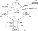
figure 5 is an illustration of an example method of using a null Mobility Management Entity Group Identifier (MMEGI) to redirect a WTRU to a dedicated CN node;
figure 6 is an illustration of an example method of redirecting a WTRU to a dedicated CN node using an MME triggered S1 handover;
figure 7 is a diagram of an example method of redirecting a WTRU to a dedicated CN node when the WTRU sends a service request;
figure 8 is a diagram of an example method for handing off a WTRU from a dedicated CN node to a non-dedicated CN node;
figure 9 is a diagram of an example method that may be undertaken by a dedicated CN node to hand off a WTRU back to a non-dedicated CN node;
figures 10A and 10B are diagrams of exemplary methods for performing WTRU redirection;
fig. 11 is an illustration of an example location update procedure initiated by an MME; and
fig. 12 is a diagram of an exemplary International Mobile Subscriber Identity (IMSI) detach procedure when the dedicated MME does not support CSFB functionality.
Detailed Description
Fig. 1A is a diagram of an example communication system 100 in which one or more disclosed embodiments may be implemented. Communication system 100 may be a multiple-access system that provides voice, data, video, messaging, broadcast, etc., content to a plurality of wireless users. The communication system 100 may allow multiple wireless users to access such content by sharing system resources, including wireless bandwidth, for example, the communication system 100 may use one or more channel access methods, such as Code Division Multiple Access (CDMA), Time Division Multiple Access (TDMA), Frequency Division Multiple Access (FDMA), orthogonal FDMA (ofdma), single carrier FDMA (SC-FDMA), and the like.
As shown in fig. 1A, the communication system 100 may include wireless transmit/receive units (WTRUs) 102a, 102b, 102c, 102d, a Radio Access Network (RAN)104, a core network 106, a Public Switched Telephone Network (PSTN)108, the internet 110, and other networks 112, although it is understood that any number of WTRUs, base stations, networks, and/or network components are contemplated by the disclosed embodiments. Each WTRU102 a, 102b, 102c, 102d may be any type of device configured to operate and/or communicate in a wireless environment. For example, the WTRUs 102a, 102b, 102c, 102d may be configured to transmit and/or receive wireless signals and may include User Equipment (UE), a mobile station, a fixed or mobile subscriber unit, a pager, a cellular telephone, a Personal Digital Assistant (PDA), a smartphone, a laptop, a netbook, a personal computer, a wireless sensor, a consumer electronics device, and the like.
The base station 114a may be part of the RAN 104, and the RAN may also include other base stations and/or network components (not shown), such as Base Station Controllers (BSCs), Radio Network Controllers (RNCs), relay nodes, and so forth. Base station 114a and/or base station 114b may be configured to transmit and/or receive wireless signals within a particular geographic area known as a cell (not shown). The cell may be further partitioned into cell sectors. For example, the cell associated with base station 114a may be divided into three sectors. Thus, in one embodiment, the base station 114a may include three transceivers, that is, each transceiver corresponds to a sector of a cell. In another embodiment, the base station 114a may use multiple-input multiple-output (MIMO) technology and thus may use multiple transceivers for each sector in the cell.
The base stations 114a, 114b may communicate with one or more WTRUs 102a, 102b, 102c, 102d over an air interface 116, which may be any suitable wireless communication link (e.g., Radio Frequency (RF), microwave, Infrared (IR), Ultraviolet (UV), visible light, etc.). Air interface 116 may be established using any suitable Radio Access Technology (RAT).
More specifically, as described above, communication system 100 may be a multiple-access system and may use one or more channel access schemes, such as CDMA, TDMA, FDMA, OFDMA, SC-FDMA, and the like. By way of example, the base station 114a and the WTRUs 102a, 102b, 102c in the RAN 104 may implement a radio technology such as Universal Mobile Telecommunications System (UMTS) terrestrial radio access (UTRA), which may establish the air interface 116 using wideband cdma (wcdma). WCDMA may include communication protocols such as High Speed Packet Access (HSPA) and/or evolved HSPA (HSPA +). HSPA may include High Speed Downlink Packet Access (HSDPA) and/or High Speed Uplink Packet Access (HSUPA).
In another embodiment, the base station 114a and the WTRUs 102a, 102b, 102c may implement a radio technology such as evolved UMTS terrestrial radio access (E-UTRA) that may establish the air interface 116 using Long Term Evolution (LTE) and/or LTE-advanced (LTE-a).
In other embodiments, the base station 114a and the WTRUs 102a, 102b, 102c may implement IEEE 802.16 (worldwide interoperability for microwave Access (WiMAX)), CDMA2000, CDMA 20001X, CDMA2000 EV-DO, interim standard 2000(IS-2000), interim standard 95(IS-95), interim standard 856(IS-856), Global System for Mobile communications (GSM), radio access technologies for enhanced data rates for GSM evolution (EDGE), GSM EDGE (GERAN), and the like.
By way of example, the base station 114B in fig. 1A may be a wireless router, home nodeb, home enodeb, or access point, and may use any suitable RAT to facilitate wireless connectivity in a local area such as a business, residence, vehicle, campus, etc. In one embodiment, the base station 114b and the WTRUs 102c, 102d may establish a Wireless Local Area Network (WLAN) by implementing a radio technology such as IEEE 802.11. In another embodiment, the base station 114b and the WTRUs 102c, 102d may establish a Wireless Personal Area Network (WPAN) by implementing a radio technology such as IEEE 802.15. In yet another embodiment, the base station 114b and the WTRUs 102c, 102d may establish the pico cell or the femto cell by using a cellular-based RAT (e.g., WCDMA, CDMA2000, GSM, LTE-a, etc.). As shown in fig. 1A, the base station 114b may be directly connected to the internet 110. Thus, the base station 114b need not access the internet 110 via the core network 106.
The RAN 104 may communicate with a core network 106, which may be any type of network configured to provide voice, data, applications, and/or voice over internet protocol (VoIP) services to one or more WTRUs 102a, 102b, 102c, 102 d. For example, the core network 106 may provide call control, billing services, mobile location-based services, pre-paid calling, internet connectivity, video distribution, etc., and/or perform high-level security functions such as user authentication. Although not shown in fig. 1A, it should be appreciated that the RANs 104 and/or the core network 106 may be in communication, directly or indirectly, with other RANs, which may employ the same RAT or different RATs. For example, in addition to interfacing with the RAN 104 using E-UTRA radio technology, the core network 106 may also communicate with another RAN (not shown) using GSM radio technology.
The core network 106 may also serve as a gateway for the WTRUs 102a, 102b, 102c, 102d to access the PSTN 108, the internet 110, and/or other networks 112. The PSTN 108 may include a circuit-switched telephone network that provides Plain Old Telephone Service (POTS). The internet 110 may include a system of globally interconnected computer network devices using a common communications protocol, and the protocol may be the Transmission Control Protocol (TCP), the User Datagram Protocol (UDP), and the Internet Protocol (IP) in the TCP/IP internet protocol suite. The network 112 may include wired or wireless communication networks owned and/or operated by other service providers. For example, the network 112 may include another core network connected to one or more RANs, which may employ the same RAT as the RAN 104 or a different RAT.
Some or all of the WTRUs 102a, 102b, 102c, 102d in the communication system 100 may include multi-mode capabilities, i.e., the WTRUs 102a, 102b, 102c, 102d may include multiple transceivers that communicate with different wireless networks over different wireless links. For example, the WTRU102 c shown in figure 1A may be configured to communicate with the base station 114a using a cellular-based radio technology and with the base station 114b, which may use an IEEE 802 radio technology.
Figure 1B is a system diagram illustrating a WTRU 102. As shown in fig. 1B, the WTRU102 may include a processor 118, a transceiver 120, a transmit/receive component 122, a speaker/microphone 124, a keypad 126, a display/touch pad 128, non-removable memory 130, removable memory 132, a power source 134, a Global Positioning System (GPS) chipset 136, and other peripherals 138. It should be appreciated that the WTRU102 may include any subcombination of the foregoing components while remaining consistent with an embodiment.
The processor 118 may be a general purpose processor, a special purpose processor, a conventional processor, a Digital Signal Processor (DSP), a plurality of microprocessors, one or more microprocessors in association with a DSP core, a controller, a microcontroller, Application Specific Integrated Circuits (ASICs), Field Programmable Gate Arrays (FPGAs) circuits, any other type of Integrated Circuit (IC), a state machine, or the like. The processor 118 may perform signal coding, data processing, power control, input/output processing, and/or any other functionality that enables the WTRU102 to operate in a wireless environment. The processor 118 may be coupled to a transceiver 120 and the transceiver 120 may be coupled to a transmit/receive component 122. Although fig. 1B depicts processor 118 and transceiver 120 as separate components, it should be understood that processor 118 and transceiver 120 may be integrated into a single electronic component or chip.
The transmit/receive component 122 may be configured to transmit or receive signals to or from a base station (e.g., base station 114a) via the air interface 116. For example, in one embodiment, the transmit/receive component 122 may be an antenna configured to transmit and/or receive RF signals. As an example, in another embodiment, the transmit/receive component 122 may be an emitter/detector configured to emit and/or receive IR, UV, or visible light signals. In yet another embodiment, the transmit/receive component 122 may be configured to transmit and receive RF and optical signals. It should be appreciated that the transmit/receive component 122 may be configured to transmit and/or receive any combination of wireless signals.
Furthermore, although transmit/receive component 122 is depicted in fig. 1B as a single component, WTRU102 may include any number of transmit/receive components 122. More specifically, the WTRU102 may use MIMO technology. Thus, in one embodiment, the WTRU102 may include two or more transmit/receive components 122 (e.g., multiple antennas) that transmit and receive radio signals over the air interface 116.
The processor 118 of the WTRU102 may be coupled to and may receive user input data from a speaker/microphone 124, a keypad 126, and/or a display/touchpad 128, such as a Liquid Crystal Display (LCD) display unit or an Organic Light Emitting Diode (OLED) display unit. The processor 118 may also output user data to the speaker/microphone 124, the keypad 126, and/or the display/touchpad 128. Further, the processor 118 may access information from and store data in any suitable memory, such as the non-removable memory 130 and/or the removable memory 132. The non-removable memory 130 may include Random Access Memory (RAM), Read Only Memory (ROM), a hard disk, or any other type of memory storage device. The removable memory 132 may include a Subscriber Identity Module (SIM) card, a memory stick, a Secure Digital (SD) memory card, and so forth. In other embodiments, the processor 118 may access information from and store data in memory that is not physically located in the WTRU102, such memory may be located, for example, in a server or a home computer (not shown).
The processor 118 may receive power from the power source 134 and may be configured to distribute and/or control power for other components in the WTRU 102. The power source 134 may be any suitable device for powering the WTRU 102. For example, the power source 134 may include one or more dry cell batteries (e.g., nickel-cadmium (Ni-Cd), nickel-zinc (Ni-Zn), nickel metal hydride (NiMH), lithium ion (Li-ion), etc.), solar cells, fuel cells, and the like.
The processor 118 may also be coupled with a GPS chipset 136, which may be configured to provide location information (e.g., longitude and latitude) related to the current location of the WTRU 102. In addition to or in lieu of information from the GPS chipset 136, the WTRU102 may receive location information from base stations (e.g., base stations 114a, 114b) via the air interface 116 and/or determine its location based on the timing of signals received from two or more nearby base stations. It should be appreciated that the WTRU102 may acquire location information by any suitable positioning method while remaining consistent with an embodiment.
The processor 118 may also be coupled to other peripheral devices 138, which may include one or more software and/or hardware modules that provide additional features, functionality, and/or wired or wireless connections. For example, the peripheral devices 138 may include accelerometers, electronic compasses, satellite transceivers, digital cameras (for photos and video), Universal Serial Bus (USB) ports, vibration devices, television transceivers, hands-free headsets, video cameras, audio cameras, and the like, A module, a Frequency Modulation (FM) radio unit, a digital music player, a video game player module, an internet browser, etc.
Fig. 1C is a system diagram of RAN 104 and core network 106 according to an embodiment. As described above, the RAN 104 may communicate with the WTRUs 102a, 102b, 102c over the air interface 116 using E-UTRA radio technology. And the RAN 104 may also communicate with a core network 106.
The RAN 104 may include enbs 140a, 140b, 140c, although it should be appreciated that the RAN 104 may include any number of enbs while remaining consistent with an embodiment. Each eNB 140a, 140b, 140c may include one or more transceivers that communicate with the WTRUs 102a, 102b, 102c over the air interface 116. In one embodiment, the enbs 140a, 140b, 140c may implement MIMO technology. Thus, for example, the eNB 140a may use multiple antennas to transmit wireless signals to the WTRU102 a and to receive wireless signals from the WTRU102 a.
Each eNB 140a, 140b, 140c may be associated with a particular cell (not shown) and may be configured to handle radio resource management decisions, handover decisions, uplink and/or downlink user scheduling, and so on. As shown in fig. 1C, enbs 140a, 140b, 140C may communicate with each other over an X2 interface.
The core network 106 shown in fig. 1C may include a mobility management gateway (MME)142, a serving gateway 144, and a Packet Data Network (PDN) gateway 146. Although each of the foregoing components are described as being part of the core network 106, it should be appreciated that any of these components may be owned and/or operated by an entity other than the core network operator.
The MME 142 may be connected to each eNB 140a, 140b, 140c in the RAN 104 via an S1 interface and may act as a control node. For example, the MME 142 may be responsible for authenticating users of the WTRUs 102a, 102b, 102c, performing bearer activation/deactivation, selecting a particular serving gateway during an initial attach of the WTRUs 102a, 102b, 102c, and the like. The MME 142 may also provide a control plane function for switching between the RAN 104 and other RANs (not shown) that employ other radio technologies, such as GSM or WCDMA.
The serving gateway 144 may be connected to each eNB 140a, 140b, 140c in the RAN 104 via an S1 interface. The serving gateway 144 may generally route and forward user data packets to/from the WTRUs 102a, 102b, 102 c. And the serving gateway 144 may perform other functions such as anchoring the user plane during inter-eNB handover, triggering paging processing when downlink data is available for the WTRUs 102a, 102b, 102c, managing and storing the context of the WTRUs 102a, 102b, 102c, etc.
The serving gateway 144 may also be connected to a PDN gateway 146 that may provide the WTRUs 102a, 102b, 102c with access to a packet-switched network, such as the internet 110, to facilitate communications between the WTRUs 102a, 102b, 102c and IP-enabled devices.
The core network 106 may facilitate communication with other networks. For example, the core network 106 may provide the WTRUs 102a, 102b, 102c with access to circuit-switched networks, such as the PSTN 108, to facilitate communications between the WTRUs 102a, 102b, 102c and conventional landline communication devices. For example, the core network 106 may include or communicate with an IP gateway (e.g., an IP Multimedia Subsystem (IMS) server), and the IP gateway may serve as an interface between the core network 106 and the PSTN 108. In addition, the core network 106 may provide the WTRUs 102a, 102b, 102c with access to a network 112, which may include other wired or wireless networks owned and/or operated by other service providers.
In order for a cellular network operator to use a dedicated CN node to serve WTRUs having certain characteristics, it is necessary to redirect such WTRUs to a dedicated CN node. The dedicated CN node may include an MME, a Serving Gateway (SGW), or a packet data network gateway (PGW). This redirection process for the WTRU may be done based on subscription information, which may be maintained on a Home Subscriber Server (HSS). The MME may download the subscription information when the WTRU registers with or attaches to the network.
A WTRU running a machine type application or otherwise having a low priority may generally use the LADP indication to indicate that it is a Low Access Priority Device (LAPD) and this indication may be signaled when the WTRU first accesses the network. The WTRU may signal its low access priority state at the radio (e.g., Radio Resource Control (RRC)) and non-access stratum (NAS) levels. The network may use the indication to take certain measures if needed, for example to apply congestion control by providing a back-off indication and a timer for such devices. However, for LAPDs that are to be redirected to dedicated CN nodes, the System Information (SI) may not use WTRU indication, but may rely on subscription information. The subscription information may contain an indication that the device in question should be served by the dedicated CN node. Since the subscription information may change at any time, there is no limit to the time at which the WTRU may be redirected to a particular CN node. For example, redirection may occur when any of the following processes occur: attach, Tracking Area Update (TAU), Routing Area Update (RAU), service request, intra-RAT idle mode mobility, inter-RAT idle mode mobility, intra-RAT handover, inter-RAT handover, roaming or shared network scenario. As an example, the service request may request an IP connection. The IP connection may establish a data connection to communicate data to and/or from the WTRU.
Exemplary methods of redirecting a WTRU to a dedicated CN node will be described below with reference to figures 2, 3, 4, 5 and 6.
Figure 2 is a diagram of an example embodiment of a method for redirecting a WTRU to a dedicated CN node upon attachment. In the embodiment shown in fig. 2, the WTRU 210 may transmit an attach request 201 to the eNB 220, which may then forward the attach request 201 to the MME 230. The attach request 201 may include the IMSI. MME 230 may contact HSS 250 and exchange update location request/answer (ULR/ULA) commands 202 with HSS 250. The MME may retrieve the WTRU subscription profile 202 from the HSS 250. The subscription profile may include an indication that the WTRU should be redirected to a dedicated CN node. The HSS 250 may inform the MME 230 that the WTRU 210 may select a CN node type in the subscription data.
The MME 230 may then send an S1AP reroute command message 203 to the eNB 220 that may provide a CN node type parameter as well as a Global Unique Temporary Identity (GUTI). The IMSI based attach may be converted into a GUTI based attach request 204. The eNB 220 may select a dedicated MME 240 based on the CN node type and may send a GUTI based attach request 204 to the dedicated MME 240. The dedicated MME 240 may contact the first MME 230, retrieve the security parameters 205, and then will continue to perform the attach procedure. For the dedicated MME 240, it may communicate with the WTRU 210 by using the security key of the first MME. The dedicated MME 240 may also select a new SGW or PGW 260 and may establish the bearer 206. The dedicated MME 240 may also contact the HSS 250 to update the location information of the WTRU 210 in the HSS 250 by performing the ULR/ULA command 207.
Although the exemplary method depicted in fig. 2 displays messages and/or steps in a particular order, it should be recognized that not all messages and/or steps are required and that the particular order may be different. Further, although steps and/or messages may be described as separate events, these steps and/or messages may be combined into a single event. Likewise, a single event may be broken down into multiple events.
Figure 3 is a diagram of another example method of redirecting a WTRU to a dedicated CN node. In the example shown in fig. 3, the WTRU 310 may send an attach request 301 to the eNB 320. eNB 320 may then forward the attach request 302 to MME 330. The MME 330 may then exchange identity request/ response messages 303a and 303b with, for example, the old MME/SGSN 340 or the WTRU 310 to obtain the IMSI. The WTRU 310, MME 330, and HSS 360 may exchange authentication information messages 305 including an authentication information request 305a and an authentication information response 305 b. Upon receiving the authentication information response message 305b, the MME 330 may receive the CN type parameter from the HSS 360. The MME 330 may then send a reroute command message 306 to the eNB 320, where the message may contain an attach request message and a core network type parameter indicating a dedicated CN type. The eNB 320 may then send an attach request message 307 to the dedicated MME 350.
Although the exemplary method depicted in fig. 3 displays messages and/or steps in a particular order, it should be recognized that not all messages and/or steps are required and that the particular order may be different. Further, although steps and/or messages may be described as separate events, these steps and/or messages may be combined into a single event. Likewise, a single event may be broken down into multiple events.
Figure 4 is an illustration of an example method of using a specific GUTI assigned by an MME along with a non-broadcast Tracking Area Identity (TAI) to redirect a WTRU to a dedicated CN node. The GUTI may be composed of an identity:
GUTI ═ PLMN ID > < MME group ID > < MME code > < M-TMSI >,
where PLMN is an abbreviation of public land mobile network and M-TMSI is an abbreviation of unique Temporary Mobile Subscriber Identity (TMSI) that is internal to the MME that allocates GUTI.
The M-TMSI is a unique 4 octet value that can identify the WTRU inside the MME, and the MME code (1 octet) represents the specific MME in the identified MME group ID (2 octets). A globally unique MME identifier (GUMMEI) may be composed of an identification according to the following equation:
GUMMEI ═ PLMN ID > < MME group ID > < MME code >
Thus, GUTI can also be expressed as:
GUTI=<GUMMEI><M-TMSI>
in the example shown in fig. 4, the WTRU 410 may transmit an attach request 401 to the eNB 420, and the eNB 420 may then forward the attach request 401 to the MME 430. MME 430 may contact HSS 460 and exchange update location request/answer (ULR/ULA) commands with HSS 460. The MME 430 may retrieve the WTRU subscription data 402 from the HSS 460. The subscription data 402 may include an indication that the WTRU should be redirected to a dedicated CN node. The HSS 460 may inform the MME 430 that the WTRU 410 may select CN type parameters in the subscription data. The MME may establish a bearer 403 for communicating with the SGW 450.
The MME 430 may allocate a particular GUTI that may contain the Mobility Management Entity Group Identifier (MMEGI) of the dedicated MME 440 and may send it to the WTRU 410 in an attach accept message 404, such as by the eNB 420. The WTRU 410 may then eventually send a TAU request 405 for MMEGI with a dedicated MME 440. The MME 430 may also send a non-broadcast TAI, such as 0000 or FFFF, to cause the WTRU 410 to perform the TAU request 405. The MME 430 may also have an MMEGI. The MMEGI of the MME 430 and the dedicated MME 440 may be preconfigured. The eNB 420 may route the TAU request 405 to the dedicated MME 440 based on the MMEGI. The dedicated MME 440 may then perform an identification procedure 406 with the MME 430 in order to obtain context information from the MME 430. The dedicated MME 440 may establish bearers 407 for communicating with the dedicated S/PGW 470. The dedicated MME 440 may also contact the HSS 460 to update the location information of the WTRU 410 in the HSS 460 by performing the ULR/ULA command 408.
Although the exemplary method depicted in fig. 4 displays messages and/or steps in a particular order, it should be recognized that not all messages and/or steps are required and that the particular order may be different. Further, although steps and/or messages may be described as separate events, these steps and/or messages may also be combined into a single event. Likewise, a single event may be broken down into multiple events.
Figure 5 is an illustration of an example method of using an empty MMEGI to redirect a WTRU to a dedicated CN node. The example shown in fig. 5 is similar to the example shown in fig. 4, except that in this example, the MME 530 may allocate a GUTI that contains the empty MMEGI of the network to which the dedicated MME 540 belongs, as well as the MME code (MMEC) of the MME 530. When the WTRU 510 performs the TAU request 505, the eNB 520 may route the TAU request 505 to the dedicated MME 540 according to the null MMEGI. Then, due to the inclusion of MMEC in GUTI, the dedicated MME 540 may contact the MME 530 and may initiate the context request/response procedure 506.
Although the exemplary method depicted in fig. 5 displays messages and/or steps in a particular order, it should be recognized that not all messages and/or steps are required and that the particular order may be different. Further, although steps and/or messages may be described as separate events, these steps and/or messages may be combined into a single event. Likewise, a single event may be broken down into multiple events.
Figure 6 is an illustration of an example method for redirecting a WTRU to a dedicated CN node using an MME triggered S1 handover. In the example shown in fig. 6, an attach procedure 601 is performed. In this example, MME 630 may establish a Packet Data Network (PDN) connection with dedicated S/PGW 650 based on the PDN connectivity information in the subscription information provided by HSS 640. Once the attach procedure 601 is completed, the MME 630 may use a new message on the S1 interface to trigger the handover 602 for the dedicated MME 660. However, as part of the handover, the serving cell and eNB 620 do not change. The MME 630 may send a forward relocation request 604 to the dedicated MME 660. The dedicated MME 660 and eNB 620 may then exchange handover request/response messages 605. The dedicated MME 660 may then send a forward relocation response 606 to the MME 630. MME 630 may then send handover command 607 to eNB 620. Dedicated MME 660 may then exchange update location request/response message 608 with HSS 640.
Although not depicted in fig. 6, the exemplary method of fig. 6 may include measurement, data forwarding, state transition, SGW relocation, and handover notification steps. Further, while FIG. 6 depicts the example method as displaying messages and/or steps in a particular order, it should be recognized that not all messages and/or steps are required and that the particular order may be different. Further, although steps and/or messages may be described as separate events, these steps and/or messages may be combined into a single event. Likewise, a single event may be broken down into multiple events.
The examples described above with respect to fig. 2, 3, 4, 5, and 6 may be supplemented by implementing additional processes. For example, a mechanism may be implemented to route security context from one MME to another, where the source MME may initiate the routing process. The target MME may request WTRU context/security parameters from the source MME. In addition, the WTRU may request dedicated bearer activation before the attachment procedure ends. The system may need to perform this procedure in order to forward it to or eventually be performed by the dedicated MME.
For embodiments involving TAU execution by the WTRU for the eNB to select a dedicated CN node, the WTRU may remain served by the suboptimal CN node for a long time since it takes a long time to perform the procedure.
In addition, some WTRUs may perform a combined registration to a Packet Switched (PS) and Circuit Switched (CS) domain via an MME, which may register the WTRU to the PS domain and then register the WTRU in the CS domain by contacting a Mobile Switching Center (MSC)/Visitor Location Register (VLR). While the MME may be a dedicated MME for the device, the MSC/VLR may not, and thus may make a better choice for the MSC/VLR. This scenario requires some mechanism to resolve.
Also, the WTRU may be handed off from the dedicated CN node back to the non-dedicated CN node for a number of different reasons. For example, the dedicated CN node may be overloaded or inoperative due to hardware or software failure, or the WTRU may be scheduled to remain with the dedicated CN node for a configured period of time. The WTRU may be handed off from the dedicated CN node to the non-dedicated CN node through some mechanism.
Further, since different classes of devices may have different traffic characteristics and data usage requirements, separate dedicated CN nodes may be required to efficiently support these classes. However, the devices are not necessarily limited to a single traffic or data usage type. The device may support multiple types of activities and behaviors over its lifetime. For example, a device may be configured to run machine-type applications, such as reporting automatic measurements at one point in time, while at another point in time, the device may be used in conjunction with human-machine interaction processing for different types of services/applications. In this case, the device may be redirected from one dedicated CN node to another node in order to meet the communication needs/characteristics of the particular service currently being used by the device. Thus, a mechanism for supporting redirection of WTRUs from one dedicated CN node to another may be needed.
Further, the WTRU may be redirected to a dedicated CN node after the attach/TAU/RAU procedure using a CN triggered handover that may change the handover process of the MME to which the eNB is connected. The procedure may be transparent to the WTRU. However, in the attach/TAU/RAU procedure, the first serving MME may have already allocated a GUTI mapped to the first serving MME itself. Thus, if a CN triggered handover process is performed, the GUTI of the WTRU will be the same as the GUTI provided by the first serving MME. This means that when the WTRU later enters idle mode, for example after its CN node is redirected, it may send a service request message to transition to connected mode. As part of the service request procedure, the WTRU may use its SAE temporary mobile subscriber identity (S-TMSI) in an RRC connection setup procedure, e.g., an RRC connection request message sent to the eNB.
Wherein S-TMSI ═ < MMEC > < M-TMSI >
The S-TMSI may identify a particular MME having WTRU context. Thus, if the GUTI is not reallocated after the CN-triggered handover process, the identity of the WTRU may point to the old MME, which may have deleted the context of the WTRU since the dedicated CN was selected in accordance with the CN-triggered handover process.
In addition, WTRUs that have registered or attached to the system may be allocated a GUTI, and a portion of the GUTI may be S-TMSI. The WTRU may include the S-TMSI in the RRCConnectionRequest message during RRC setup for sending NAS messages such as TAU or service request. The GUMMEI may be included in the RRCConnectionSetupComplete message. After the eNB receives the RRCConnectionSetupComplete message, the eNB will have both S-TMSI and GUMMEI. The GUMMEI may point to registered PLMNs and MME groups, while the S-TMSI may contain MME codes pointing to specific MMEs within the MME group identified by the MMEGI.
For empty MMEGI, the eNB may receive an empty MMEGI pointing to a dedicated MME and an S-TMSI pointing to a non-dedicated MME (e.g., an MME assigned a GUTI with empty MMEGI) that currently has WTRU context. Thus, NAS messages such as TAU or service requests may be forwarded to the dedicated MME based on the empty MMEGI. If the NAS message is a TAU, the TAU may force the dedicated MME to retrieve the WTRU context from the non-dedicated MME. However, if the NAS message is a service request and the NAS is sent to the dedicated MME, the dedicated MME may not be able to retrieve the WTRU context. Thus, the MME may reject the WTRU using the cause code "# 9-WTRU identity cannot be derived by the network", which may result in the WTRU re-attaching to the system and deleting its assigned GUTI directed to the dedicated CN. In this scenario, the process may restart again.
The process of using dedicated CN nodes may take several forms. For example, a dedicated CN may include using a dedicated MME, a dedicated SGW, and a shared PGW. In another network, the policy of using a dedicated CN may further include using a dedicated PGW. If the WTRU is already registered or attached to the system, its PGW may have been selected. Generally, the PGW selection process may be performed during the attachment process. Thus, if the WTRU needs to use a dedicated PGW, the WTRU may perform the PGW selection process again. As a result, the WTRU may perform a re-attach procedure. The WTRU may also reselect the PGW without performing a re-attach. If the WTRU performs the re-attach process, the re-attach process may be performed on the serving MME or may be performed on the dedicated MME. Both of these options have certain advantages and disadvantages. For example, if the re-attach process is performed on the serving MME and the MME is a non-dedicated MME, the serving MME may be burdened with the signaling. After the attachment procedure is over, the serving MME may attempt to redirect the WTRU to the dedicated MME. Furthermore, the previous serving MME may have selected the appropriate PGW. Since the purpose of the redirection is to release the non-dedicated MME from the WTRU, this embodiment may force certain signaling on the non-dedicated MME. Thus, after redirection, the WTRU may be re-attached in different ways on either the non-dedicated MME as the source or the dedicated MME as the target.
If the WTRU is registered in both the MME and the MSC/VLR for the purpose of using Circuit Switched Fallback (CSFB), the MME-initiated S1 handover process may relocate the WTRU to a dedicated MME, as described above. However, the WTRU may not be able to use CSFB since the dedicated MME may not have CSFB context and the VLR may keep the SGW associated with the old MME. There is thus a need for a method for establishing an SGW association between a new dedicated MME and an MSC/VLR.
The embodiments described herein may provide procedures and mechanisms that may redirect WTRUs to dedicated CN nodes, for example, in accordance with the examples described above with respect to figures 2, 3, 4, 5, and 6. The embodiments described below are described in the context of LTE as a RAT. However, the embodiments are equally applicable to either RAT.
In one exemplary embodiment of the method for facilitating redirection to a dedicated CN, a periodic timer with a short set time may be used. The periodic timer is a timer that is started on the WTRU when a signaling connection, such as a NAS signaling connection, is released with the serving CN node, such as the MME. In LTE, for example, the periodic TAU timer is a General Packet Radio Service (GPRS) timer defined to have a value ranging from 2 seconds to 3 hours and 6 minutes. For example, the MME may allocate a short periodic timer period when the MME determines from the available information that the WTRU should be redirected to a dedicated CN node, or when the MME allocates a special GUTI or GUMMEI. For example, the MME may assign a timer period shorter than a default value, which is 54 minutes for the TAU timer in LTE. This may allow the WTRU to be redirected to the dedicated CN node faster because the WTRU may perform periodic TAU in a shorter period of time than using a default value.
The MME was described in the previous example; however, the embodiments herein may be applicable to UMTS/GERAN scenarios where the Serving GPRS Support Node (SGSN) may be a serving node for the PS domain and the periodic timer may be referred to as a periodic RAU timer. The MSC/VLR may be a NAS entity in the CS domain, with the corresponding timer referred to as a periodic Location Area Update (LAU) timer.
In another embodiment, the network may inform the WTRU whether it is a private network. The network may use broadcast or dedicated signaling to send an indication. The broadcast signaling may be implemented using RRC messages, such as System Information Blocks (SIBs), while the dedicated signaling may be implemented using RRC and/or NAS messages. For example, a new Information Element (IE) may be included in any NAS message to indicate whether the CN node is a dedicated CN node. This IE may be included in the attach accept message, the TAU accept message, or any NAS session management message. Based on the indication, the WTRU may decide to perform a re-registration process (using an attach or TAU accept message) so that the RAN may select a different/dedicated CN node.
The WTRU may also provide a dedicated CN indication to the eNB to let the eNB know to forward the NAS message to the appropriate dedicated CN node. The WTRU may provide such an indication in an RRC message, such as an RRC connection request message or an RRC connection setup complete message. The WTRU may be configured to use a dedicated CN node, or may be configured to provide an indication that it is subject (subject to) to use a dedicated CN node using: access Network Discovery and Selection Function (ANDSF), open mobile alliance device management (OMA DM) procedure, Short Messaging Service (SMS), or any other provisioning method, which may also be pre-provisioned in the Universal Integrated Circuit Card (UICC)/Mobile Equipment (ME).
If the eNB receives an indication that the WTRU is amenable to being served by a dedicated CN node, the eNB may select one dedicated CN node to forward the NAS message. The eNB may also receive an identity (which may be included by the WTRU in the same manner as described above) that the eNB may use to resolve the particular CN node to which the WTRU's NAS message is intended. Alternatively, the eNB may be configured with the address of the dedicated CN node, and the eNB may use the configuration to select the dedicated node. Alternatively, the selection of the CN node may be dependent on or independent of the indication or identity provided by the WTRU as described above.
Additionally or alternatively, if the WTRU is configured to use a dedicated CN node, the WTRU may use a new establishment cause to indicate that it is amenable to selection of the dedicated CN node. The NAS layer message may contain this information and may provide the RRC layer with an establishment cause. Optionally, a new call type may be defined, such as dedicated CN signaling or dedicated CN data, to indicate to the RRC that the WTRU should use a dedicated CN node. The RRC may then set or contain certain RRC parameters accordingly. Examples of parameters may include an establishment cause and/or other indications as described above. Also, when the network broadcasts that it is a dedicated node, the WTRU may use a specific random number in the RRC connection request message instead of the S-TMSI. As an example, this particular random number may be identified by the eNB by means of a predefined bit sequence. For example, the most significant bits of the random number have the predefined sequence. Then, after receiving the RRC connection request with the specific random number, the eNB will be able to route the initial NAS message to the dedicated node or inform the first MME that the WTRU is subject to the selection of the dedicated CN node.
Further, when the WTRU indicates to the eNB that it is configured to use the dedicated CN node, the eNB may communicate the information to the first MME. In this way, if the MME is already a dedicated CN node, the MME may continue to perform the attach procedure, and if not, it may request or instruct the eNB to reroute the attach message to another MME.
The MME may establish an SGW association with the VLR if the WTRU has requested a combined attach. Thus, the WTRU performs the TAU later according to one of the solutions described above, and the TAU may be combined, which causes the new relay MME to contact the VLR and establish the SGW association.
Alternatively, the first MME may not contact the VLR, instead it may inform the WTRU that a new CS registration process is proposed or needed in an attach accept message. As an example, the attach accept message may include a new IE or a new reason. This process would be very useful if the sharing process was deployed in the CN and the operator performing the sharing has agreed to use the designated entity for the dedicated CN node.
The above describes the rerouting option in the case where a CN node, such as an MME, informs an eNB to route a NAS message to another CN node, and the CN node is a known dedicated CN node or is expected to be a dedicated CN node. In one embodiment, the new MME may acquire the WTRU's NAS messages, such as attach request, authentication context, vector, or any generic security context. Thus, the reroute message may contain this information. The security context may be included in the reroute. As an example, a security context may be included in addition to the attach message and the CN type.
There are at least two ways to implement the inclusion of generic security information in rerouted messages. The MME may send a container containing both WTRU messages and security parameters. As an example, the security parameters may include authentication vectors and/or other security contexts, parameters, or algorithms. Alternatively, one IE may be included for each of the portions. For example, an IE corresponding to a WTRU message, an IE corresponding to an authentication parameter, and an IE corresponding to a security parameter, etc. may be included.
In one embodiment, the dedicated CN node may run NAS Security Mode Command (SMC) procedures. The first MME may run identity request/response and authentication request/response procedures and the dedicated CN node may run SMC procedures. The operator may choose not to run, run one, or run more than one process before rerouting the message to the dedicated CN node. For example, the first MME may be configured to not run identification, authentication, or SMC procedures. The MME may then route the attach message. Absent an IE associated with or specifically defined for the WTRU identity, authentication context, and other security contexts, such as ciphering and/or integrity protection algorithms, the dedicated CN node is caused to run corresponding identity, authentication, and SMC procedures. Alternatively, the first MME may only run identity request/response procedures and may include WTRU identity related information such as IMSI in the reroute message. If there are no authentication and security parameters, the dedicated CN node may be advertised to run procedures on these parameters. The first MME may contain no relevant information or may also contain the corresponding IE, but sets the value to a well-known value, e.g. NULL or zero value. A known value may indicate to the dedicated CN node that it should run these procedures with the WTRU.
Alternatively, the first MME may explicitly indicate which procedures it has run and which procedures need to be run by the dedicated MME. Alternatively, the first MME may indicate which procedures it has run, and the dedicated MME may implicitly know which other procedures need to be run. For this purpose, the first MME may use a bitmap, where each bit position corresponds to a procedure, and the setting of the bit may be "1" or "0", which may imply that the procedure has been run. Other explicit or implicit indications may also be used, such as IE containing process-by-process.
As described above in relation to the previous embodiments, the MME may receive subscription information by communicating with the HSS. In one example, the HSS may push the subscription information to the MME when the subscription information changes.
For example, when the CN updates WTRU profile information indicating that the WTRU should be served by a dedicated CN node, the WTRU's subscription information may change on the CN. The MME or SGSN may page the WTRU when the subscription information of the WTRU changes. The MME or SGSN may use the IMSI as the paging identity of the WTRU. By paging the WTRU with the IMSI in the PS domain, the WTRU may be forced to re-attach to the system. Thus, when paged with an IMSI, the WTRU may re-attach to the system, and the MME or SGSN may attach using any redirection solution to redirect the WTRU to a dedicated CN node. Thus, a WTRU profile information change on the CN may trigger the CN to page the WTRU.
The WTRU profile information change may also trigger the CN to page the WTRU using other identities, such as S-TMSI in LTE and P-TMSI in UMTS. When the WTRU enters connected mode, if the CN node is the MME, the WTRU identity may be reallocated using a GUTI reallocation order. If the CN node is the SGSN, the WTRU identity may be reallocated using a P-TMSI reallocation order. If the CN node is MSC/VLR, then the WTRU identity may be reassigned using the TMSI reassignment order.
As mentioned above, the network may use the S-TMSI to page the WTRU. Once the service request procedure is finished, the network may initiate a detach procedure, e.g., by sending a detach request to the WTRU, and the network may indicate "re-attach required". Doing so may cause the WTRU to re-attach to the system.
Figure 7 is a signaling diagram illustrating a method for redirecting a WTRU to a dedicated CN node when performing a service request procedure. At 701, the network, which may be, for example, the MME 720, may cause the WTRU 710 to enter connected mode by paging the WTRU 710. The MME 720 may also be an SGSN or an MSC. At 702, the WTRU 710 may perform a service request procedure. The WTRU 710 may initiate the NAS connection establishment process by sending a service request to the network. By way of example, the network may be the MME 720. At 703, the MME 720 may trigger the GUTI reallocation procedure and may respond to the WTRU 710 with a non-broadcast TAI or a Routing Area Identity (RAI). Alternatively or additionally, the GUTI reallocation procedure may comprise a GUTI directed to a dedicated core network. The MME 720 may then release the RAN resources associated with the WTRU 710 at 704. The WTRU 710 may then go to idle mode. Thus, the next time the WTRU 710 enters connected mode, the WTRU 710 may include the GUTI or at least a portion of the GUTI, e.g., the S-TMSI, in the TAU request and may be redirected to the dedicated MME, 705. A WTRU 710 receiving a TAI or RAI may trigger the WTRU 710 to perform a TAU/RAU procedure and may send a TAU/RAU request. At 706, NAS redirection may be performed. Although not shown in fig. 7, the WTRU may communicate with the MME through the eNB. The MME or eNB may redirect the WTRU to a dedicated MME through a NAS redirection procedure.
Additionally or alternatively, the service request procedure may respond by sending a GUTI reassignment order, in which WTRU 710 may consider the procedure to have ended and may stop the timer protecting the service request procedure. Alternatively, the GUTI reallocation procedure may be initiated after the CN node triggers a handover command.
The MME 720 may also run the GUTI reallocation procedure if the first message received from the WTRU 710 is a detach request message. Doing so also enables the system to redirect the WTRU 710 to a dedicated CN node when the WTRU 710 next attaches to the system. Thus, for any NAS procedure that is not an attach or TAU procedure, if the MME knows that the WTRU 710 is subject to redirection to a dedicated CN node, the MME 720 may run a GUTI reallocation procedure to allocate an identity that points to a specific CN node.
Although FIG. 7 depicts the example method as displaying messages and/or steps in a particular order, it should be recognized that not all messages and/or steps are required and that the particular order may be different. Further, although steps and/or messages may be described as separate events, these steps and/or messages may be combined into a single event. Likewise, a single event may be broken down into multiple events.
The examples described above may be applied to LTE, GERAN and UMTS systems, in which the corresponding identity reallocation procedure may be used in accordance with the system/domain. For example, if the WTRU has a signaling connection with the MSC in a GERAN or UMTS system, the MSC may run the TMSI reallocation order procedure described above. For the SGSN, the P-TMSI reallocation order procedure may be run in the manner described above.
To speed up the redirection procedure, the CN may use the cause code to release the WTRU's connection in order to force the WTRU to re-establish a new NAS connection. A new cause code may be defined at the RRC layer to indicate that the WTRU should re-attach to the system. Alternatively, a new cause code may be defined for the WTRU to perform the TAU procedure.
The examples described above may be applied to GERAN and UTRAN systems that may use similar procedures, such as LAU for CS domain and RAU for PS domain. Furthermore, the eNB may be replaced by a BSC and RNC for GERAN and UMTS systems, respectively.
Alternatively, existing mechanisms may be used to quickly redirect the WTRU. The MME may use a load balancing procedure, which may cause the S1 and RRC connection to be released. The RRC may include a release code set to "load balancing TAU needed", and the release code may force the WTRU to perform TAU. Thus, by using a load balancing procedure, fast redirection may be allowed in case of GUTI being reallocated so that it may be directed to a specific MME.
Thus, for any NAS procedure, such as a TAU or service request, GUTI reallocation may be used to first provide the WTRU with an identity pointing to a particular CN, and then the WTRU's connection may be released in the manner described above to speed up the redirection process.
Another alternative is that for a specified NAS procedure or a Connection Mode (CM) service request (MSC), the CN node may first run a corresponding identification procedure. After its termination, the CN node may reject the NAS procedure using service rejection or CM service rejection, and may indicate that the WTRU is implicitly detached. For example, the reason code for the PS domains of UMTS and LTE may be used. Other cause codes that may cause the WTRU to re-establish the NAS signaling connection may also be used, such as re-registration, if appropriate. Alternatively, a new cause code may be defined and the WTRU may be forced to re-register with the system. For example, the WTRU may perform an attach or update procedure, such as TAU, RAU, or LAU.
In one embodiment, the CN node may reassign the identity after the service request procedure is ended. For example, the MME may send a GUTI reassignment order message, the SGSN may send a P-TMSI reassignment order message, or the MSC/VLR may send a TMSI reassignment order message.
In one example embodiment, wherein the CN node is an MME, the MME may receive a service request message or an extended service request message and profile information of the WTRU provided by the HSS. The profile information may indicate that the WTRU should be served by a dedicated CN node. The MME may initiate a GUTI reallocation order procedure/message before or after the service request procedure is ended. If the GUTI reallocation order is run before the service request procedure is finished, the MME may optionally send a service reject with a cause code that may force the WTRU to re-attach to the system.
In an example embodiment, wherein the CN node is an SGSN, the SGSN may receive the service request message and profile information of the WTRU provided by the HSS/HLR. The profile information may indicate that the WTRU should be served by a dedicated CN node. The SGSN may initiate a P-TMSI reallocation order procedure/message before or after the service request procedure is finished.
In an example embodiment, wherein the CN node is an MSC/VLR, and the MSC/VLR may receive the CM service request message and profile information of the WTRU provided by the HSS/HLR. The profile information may indicate that the WTRU should be served by a dedicated CN node. The MSC/VLR may initiate the TMSI reallocation order procedure/message before or after the service request procedure is ended.
The redirection process using GUTI reassignment may be used for any initial NAS message sent by the WTRU, such as a page response in GERAN, and is not limited to service request or CM service request messages. For any NAS procedure or message sent by the WTRU, the CN may decide to reallocate the identity before or after the procedure is over, e.g., by means of a GUTI reallocation order. For example, the CN may be decided based on subscription information changes, such that it may indicate to use a dedicated CN node for the WTRU.
Further, the CN node may be, for example, an MME, SGSN, or MSC/VLR, and may run the identity reallocation procedure at any time when the WTRU is in connected mode. For example, the identity reallocation procedure may include a GUTI reallocation order for MME, a P-TMSI reallocation order for SGSN, or a TMSI reallocation order for MSC/VLR. In one example embodiment, where the WTRU may be involved in an ongoing data transmission, an appropriate WTRU identity reallocation procedure may be performed if the WTRU's subscription or profile information is updated such that the WTRU should be served by a dedicated CN node.
Additional embodiments for resolving how to handle race conditions in a redirection procedure using CN-triggered handover are disclosed herein. In one embodiment, the CN-triggered handover may force the eNB to select a new MME without affecting the WTRU. The CN may trigger the handover at any time after the end of the attach procedure. If the CN triggers a handover, the WTRU or eNB may initiate a different procedure. For example, the WTRU may initiate a session management procedure to initiate activation of a PDN connection or a new dedicated bearer. Additionally or alternatively, the MME may initiate a handover initiated by the MME. In another example embodiment, the eNB may be in the process of handing off the WTRU to another eNB using S1 or X2 handover, while the MME may initiate a handover process for the eNB to redirect the WTRU.
Although CN-initiated handover scenarios are used to illustrate methods for handling race conditions, these methods may also be applied to similar race conditions in other solutions.
In another embodiment, a contention condition for CN triggered handover processing may be handled during an ongoing RAN handover procedure. Upon receiving a CN-triggered handover request that requires redirection of the WTRU, if a RAN node, such as an eNB, RNC, or BSC, is performing a handover, the RAN node may reject the request and may indicate that its cause is a handover. Upon receiving a rejected request originating from the RAN node for a CN triggered handover, the CN node may wait for the handover to end before initiating a new request. The CN may determine that the handover is complete when the CN receives a handover complete acknowledgement from the target RAN node. For example, in LTE, upon receiving a path switch request message from the target eNB, the CN may determine that the handover is complete.
In another embodiment, what is addressed is the handling of other procedures in the course of performing a CN-initiated handover. In a CN-initiated handover procedure, the CN may receive a request from a WTRU or SGW/PGW to activate, deactivate, or modify a bearer. The handling of this request may depend on whether the handover is successful or failed.
Upon receiving a request from the SGW/PGW to activate, deactivate, or modify a bearer and the MME has initiated a handover to redirect the WTRU, the MME may take the following actions. The MME may reject the request and may contain a cause code indicating that a handover is ongoing. For example, if the MME receives a create bearer request from the SGW, the MME may respond with a create bearer response and may contain a cause code to indicate that a handover is in progress. The MME may contain a timer after which the destination node, such as the SGW or PGW, may retry. Upon receiving a response indicating that a handover is occurring, the SGW or PGW may reattempt the request after a pre-configured certain time has elapsed or after an indicated time has elapsed. Upon receiving the response, the SGW may either retry after a certain time has elapsed, as described above, or instead send a create bearer response to the PGW and include the cause code and timer value if present. Later, the PGW may reattempt the request. Alternatively, existing cause codes may be used. For example, the WTRU may reject or not page the WTRU.
When the MME receives a request from the WTRU to activate, deactivate, or modify a bearer and the MME has initiated a handover to redirect the WTRU, the MME may take the following actions. The MME may ignore the request, which may eventually cause the timer on the WTRU to expire. The WTRU may request again later. The MME may reject the request and may contain an existing or entirely new cause code that may inform the WTRU that the handover has not been completed or that the WTRU should reattempt. The MME may reject the request and may contain a NAS session management back-off timer whose value is set to zero or any other non-zero but short value. If the MME receives confirmation that the handover has been successful, the MME may initiate a routing procedure for the request. If a new MME requests the context of the WTRU, the MME may forward the request to the new MME. New IEs or procedures may be defined. The new IE may be included in a context response sent by the source MME to the target dedicated MME. This new IE may hold the NAS message for the WTRU. Once received by the target MME, the target MME may process the request and may respond to it accordingly.
Alternatively, if the eNB determines that there is a handover process in progress for redirecting the WTRU, the eNB may not forward the request to the source MME. Later, the eNB may forward the NAS message to the target MME after the handover is over. Alternatively, the eNB may not acknowledge receipt of the message via RRC, PDCP, RLC, MAC, etc., which then forces the WTRU to resend the NAS message. By that time, if the handover is over, the eNB may forward the NAS message to the new MME.
In one embodiment, a CN node such as an MME, SGSN or MSC subclass may perform the process of reassigning WTRU identities after the handover is completed in order to provide the WRU with a new ID pointing to the actual serving CN node. This serving CN node may be the CN node with WTRU context after handover. After the CN triggers the handover, the target dedicated MME may now have the WTRU context and may initiate a GUTI reassignment order to the WTRU and specify a new GUTI. Also, the target or new SGSN may run a P-TMSI reallocation procedure after the handover is completed to provide the WTRU with a new identity that may point to the serving SGSN. Also, the target or new MSC/VLR may run the TMSI reallocation procedure after the handover is over in order to provide the WTRU with a new identity pointing to the serving MSC/VLR.
In the identity reallocation procedure described above, the CN may include a non-broadcast identity in the procedure. Exemplary identity reallocation procedures include a GUTI reallocation order for LTE, a P-TMSI reallocation order for the PS domain of a GPRS/UMTS system, or a TMSI reallocation order for the CS domain of a GPRS/UMTS system. In one LTE example, in the GUTI reallocation order procedure described above, the MME may also include a non-broadcast TAI in a message sent to the WTRU, such as a GUTI reallocation order. This helps to speed up the registration process from the WTRU. When the WTRU reads the system information, it may recognize that the allowed TAI list provided by the MME in the TAI reassignment command is not equivalent to what is actually being broadcast by the RAN. Therefore, the WTRU may immediately send a registration message, such as a TAU, to the MME.
Similar examples may apply the corresponding messages to the SGSN and MSC/VLR. For example, in the P-TMSI reallocation order procedure, the SGSN may also include a non-broadcast RAI for the WTRU. Similarly, if the WTRU recognizes that the broadcast RAI is not equivalent to the non-broadcast RAI provided in the P-TMSI reallocation order, the WTRU may send an RAU to the SGSN. Also, the MSC/VLR may also include a non-broadcast Location Area Identity (LAI) for the WTRU during the TMSI allocation command. If the WTRU recognizes that the broadcast LAI is not equivalent to the non-broadcast LAI provided in the TMSI reallocation order, the WTRU may send the LAU to the MSC/VLR.
Additional embodiments provide solutions for switching from a dedicated CN to a non-dedicated CN. When a WTRU has attached/registered to a dedicated CN node, the WTRU may find it desirable to switch back to a non-dedicated CN node. The following event may trigger a switch back to processing of the non-dedicated CN node. The WTRU may receive an indication from the dedicated CN node that it is overloaded. In such a scenario, the WTRU may receive an attach reject, TAU reject, or service reject with a mobility management back-off timer from the dedicated CN node. An upper layer data transmission error may indicate a failure of a dedicated CN node, such as a dedicated SGW or PGW. The WTRU may be scheduled to remain attached to the dedicated CN node for some portion of the day and then to be attached to the non-dedicated CN node for the remainder of the day. The Access Point Name (APN) to which the WTRU requests access may not be supported by the dedicated CN node.
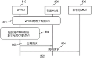
Figure 8 is an illustration of an example method for a WTRU to handover from a dedicated CN node to a non-dedicated CN node. In the example shown in fig. 8, a WTRU 810 may attach to a dedicated CN at 801. At 802, the satisfied condition may trigger the WTRU 810 to switch from the private network to the non-private network. The WTRU 810 may detach from the dedicated CN node by sending a detach request at 803 and may then initiate a new attach request at 804. New types of separation may be defined herein. A new indication may be included in the new attach request to inform the non-dedicated MME 830 that it should ignore the subscription data indicating that the WTRU 810 should be redirected to a dedicated CN node. The attach request may also include an indication of the length of time the non-dedicated MME 830 should ignore the subscription data. Upon receiving this indication, the non-dedicated MME 830 may treat the attach request as a normal WTRU attach request and may not redirect the attach request, and thus the WTRU 810, to a dedicated CN node.
For the eNB to route the new attach request to the non-dedicated MME 830, the WTRU 810 may ignore the S-TMSI from the RRC connection request message with the MME code of the dedicated MME 820. The above described method of forcing the eNB to select a dedicated CN node by including some indication in the RRC message can also be used to force the eNB to select a normal MME for this new attach request.
Additionally or alternatively, the WTRU 810 may indicate to the non-dedicated MME 830 how long the WTRU should be attached to the non-dedicated CN. After the period of time, the non-dedicated MME 830 may redirect the WTRU 810 to the dedicated MME 820 again. Alternatively, the length of time for attaching the WTRU 810 to the non-dedicated MME 830 may be preconfigured in the MME or may be included in the WTRU's subscription data.
Although the exemplary method depicted in fig. 8 displays messages and/or steps in a particular order, it should be recognized that not all messages and/or steps are required and that the particular order may be different. Further, although steps and/or messages may be described as separate events, these steps and/or messages may be combined into a single event. Likewise, a single event may be broken down into multiple events.
Figure 9 is an illustration of an example method of a procedure initiated by a dedicated CN node to hand off a WTRU back to a non-dedicated CN node. At 901, the WTRU 910 may attach to a dedicated MME 920. The dedicated MME 920 may decide to detach the WTRU 910 for a variety of reasons. For example, the dedicated MME 920 may be overloaded and decide that the WTRU 910 should be detached 902. At 903, the dedicated MME 920 may explicitly send the WTRU 910 a detach request with some indication that the WTRU should re-attach to the non-dedicated MME 930. As an example, a new separation type may be defined to serve as the indication. After the detach request, the WTRU 910 may send an attach request to the non-dedicated MME 930 at 904. As described above, the attach request may include a new indication to the non-dedicated MME 930 that it should ignore subscription data indicating that the WTRU should be redirected to the dedicated CN node, and may also include an indication of the duration for which the non-dedicated MME 930 should ignore subscription data. Alternatively, although not depicted in fig. 9, after receiving the detach request from the dedicated MME 920, the WTRU 910 may explicitly send a detach request to detach from the dedicated MME 920 and then may re-attach to the non-dedicated MME 930.
Although not depicted in fig. 9, the dedicated CN node may include an indication in the TAU reject or service reject message to request the WTRU 910 to re-attach to a non-dedicated CN node.
Although FIG. 9 depicts the example method as displaying messages and/or steps in a particular order, it should be recognized that not all messages and/or steps are required and that the particular order may be different. Further, although steps and/or messages may be described as separate events, these steps and/or messages may also be combined into a single event. Likewise, a single event may be broken down into multiple events.
As described above, the target MME may receive NAS messages, such as service requests, from WTRUs whose context is not encompassed by the MME. To avoid this, the eNB may include the GUMMEI and S-TMSI in the initial WTRU message sent on the S1AP interface. Thus, when the eNB receives the GUMMEI from the WTRU as part of the RRC connection procedure, e.g., in RRCConnectionSetupComplete, the eNB may verify whether the GUMMEI contains an empty MMEGI.
If the GUMMEI contains an empty MMEGI, the eNB may include the GUMMEI in the initial WTRU message sent to the target MME. In this case, the initial WTRU message will be sent to the dedicated MME since the eNB will send the NAS message to the dedicated MME based on the GMMEI. The dedicated MME may receive an initial NAS message for the WTRU in question via an eNB.
The target MME may know whether it is configured to operate as a dedicated MME. The target MME can verify whether the MMEGI in the GUMMEI has the value of an empty MMEGI. If an empty MMEGI is included in the GUMMEI, the target MME may process the NAS message and not reject the message even if the MME does not contain context for the WTRU.
The target MME may use information received from the eNB to retrieve the WTRU context from the source MME, for example, by using GUMMEI and S-TMSI. For example, if the initial NAS message is an extended service request or service request (collectively referred to as a service request), the target MME may retrieve the WTRU context from the source MME based on the checking described above, even if the target MME does not contain context for the WTRU.
While the target MME retrieves the context, the source MME may provide the target MME with subscription information indicating whether the WTRU should be served by the dedicated CN. The source MME may provide an indication to the target MME that the WTRU should be served only by the dedicated MME, or by the dedicated MME and SGW, or by the dedicated MME, SGW and PGW. For example, the target MME may determine to trigger the WTRU to perform a re-attach if the subscription information or the context information indicates that the PGW should be reallocated as a dedicated PGW.
Alternatively, after the target MME gets the WTRU context, the target MME may use Domain Name System (DNS) or other methods to verify if it needs to reallocate the WTRU's PGW and force the WTRU to re-attach.
After retrieving the context, the target MME may respond to the WTRU using any of the methods described herein.
Even if the MME retrieves the WTRU context, the MME may respond with a service reject but include a cause code that triggers the WTRU to re-attach to the system, optionally with a cause code that does not cause the WTRU to delete the GUTI.
For example, the MME may send a service reject and may contain a cause code "# 10-implicit detach". Alternatively, the MME may use the cause code "# 40-no EPS bearer context activated". This service rejection may be used with the cause code as described above if the MME needs to reallocate dedicated PGWs. If the NAS message is a TAU request, the MME may still reject the TAU and may contain a cause code forcing the WTRU to re-attach to the system, optionally, the cause code used may not result in deletion of the GUTI at the WTRU, e.g., cause code #10 or # 40.
In another embodiment of the method of forcing a WTRU to re-attach to the system, the MME may initiate bearer context deactivation and may identify the bearer as a default bearer. For any reason that the MME wishes the WTRU to re-attach to the system or at any time, e.g., for the purpose of using a dedicated CN node, the MME may send a deactivate EPS bearer context request and may include a cause code that triggers the WTRU to eventually re-attach to the system. This reattachment process may be performed after the explicit detachment has been performed.
For example, the MME may use the cause code "# 39-request re-request". This triggers the process of redirecting the WTRU to the dedicated CN, regardless of the actual redirection solution. Redirection solutions may include attachment rerouting solutions or null MMEGI solutions, etc. The MME may deactivate the default bearer and all PDN connections of the WTRU at any time and with or without GUTI reallocation performed.
Alternatively or additionally, the MME may initiate a detach procedure if the MME requires the WTRU to re-attach to the system for the purpose of redirecting the WTRU to a dedicated CN node. At any time, the MME may decide to redirect the WTRU and may require the WTRU to re-attach, for example, to reselect another dedicated PGW. The MME may send a detach request message to the WTRU and may contain a detach type IE with a value set to "re-attach required". The method may be deployed in conjunction with other methods described herein. For example, the MME may first perform GUTI reallocation and then initiate the detach procedure by sending a detach request and setting a "reattach needed" indication as the detach type.
The MME may use the retrieved WTRU context and may accept the WTRU's request if the MME may continue to serve the WTRU without PGW reallocation. However, if the MME needs to reallocate SGWs, the MME may additionally trigger SGW reallocation in order to pick up the SGW as the dedicated SGW. The MME may perform the SGW reallocation process as part of or after the service request procedure is ended.
As described above, the WTRU re-attach process may be triggered by either the source MME, which may be a non-dedicated MME, or the target MME, which may be a dedicated MME. A method of triggering WTRU re-attachment by a non-dedicated MME and a dedicated MME will now be described.
For WTRUs that are already registered in the system, reselection of the PGW may require re-attachment of the WTRU if a dedicated PGW is required.
The configuration in the source MME may indicate whether the reattachment process should be triggered by the source MME before redirection. When the source MME receives updated subscription information for redirecting WTRUs, or because local policy requires redirecting the WTRU to a dedicated CN, the source MME may first verify whether a reselection of PGW is required. This may be done using DNS or other local policy or other functionality. If the PGW also needs to be redirected, the MME may verify its local policy to see if it should re-attach the WTRU or redirect the WTRU and leave the target MME to perform the re-attach process.
The MME may redirect the WTRU using any of the methods described above if the MME policy or configuration indicates that the MME should perform WTRU re-attach processing. For example, the MME may initiate the WTRU detach request procedure and may contain a type set to "re-attach required" or the MME may deactivate the PDN connection of the WTRU. While deactivating the last PDN connection or the last default bearer, the network may indicate "# 39-request reactivation" in the session management message as described above.
After re-attaching the WTRU in the manner described above, the source MME may redirect the WTRU to a dedicated target MME. The source MME may forward information to the target MME, such as when the target MME attempts to retrieve the WTRU context from the source MME. The information may indicate that only the MME and/or SGW need to be redirected to avoid PGW reselection processing that may trigger other reattachment processing at the target MME.
The source MME may have a configuration that allows the target MME to re-attach the WTRU if needed. As such, when the subscription changes such that the WTRU should be redirected to the dedicated MME, the source MME may perform the redirection and the target MME may be left to evaluate whether the WTRU still needs to re-attach. After redirecting the WTRU, the target MME may retrieve the WTRU context from the source MME. The source MME may include relevant subscription information in the context of the WTRU to inform the target MME whether the PGW should also be redirected. Alternatively, the target MME may also determine whether the PGW needs to be reallocated once subscription information is received from the source MME or from the HSS. As an example, the target MME may use DNS or other methods to make the determination.
If the PGW needs to be reallocated, the target MME may initiate the WTRU re-attach process using any of the methods described above. For example, the target MME may reject the NAS message of the WTRU and may indicate that a re-attach process is required.
It is worth mentioning that all the methods and procedures described above are applicable to other RATs, such as GERAN and UTRAN systems, with corresponding procedures on the NAS or RAN-to-core network interface/protocol. Thus, even though the methods are described in the context of LTE, they are correspondingly applicable to other systems.
Figures 10A and 10B are signal flow diagrams of exemplary methods for performing WTRU redirection. Referring to figure 10A, at 1001, the WTRU1010 registers with a non-dedicated serving MME 1030. At 1002, the HSS 1060 may update the user profile in the serving MME 1030 to indicate that the WTRU1010 should be served by the dedicated MME 1040. HSS 1060 may perform this by pushing subscription information to serving MME 1030. At 1003, the serving MME 1030 may verify whether a PGW needs to be reselected or redirected to a dedicated PGW. At 1004a and 1004b, if the WTRU1010 is in idle mode, the serving MME 1030 may optionally actively redirect the WTRU1010 by paging the WTRU 1010. The serving MME 1030 may send an S1AP paging message to the eNB 1020 at 1004a, and the eNB 1020 may send an RRC paging message to the WTRU1010 at 1004 b. Alternatively, the serving MME 1030 may wait until the WTRU1010 performs the service request or the extended service request at 1005. If the serving MME 1030 waits until the WTRU1010 performs a service request, paging may not be performed.
If the WTRU is already in connected mode, step 1006 of figure 10A occurs directly after 1003. At 1006, the serving MME 1030 may reallocate the GUTI to the WTRU1010 based on the updated subscription information. This may be done by the serving MME 1030 sending a GUTI reallocation order to the WTRU1010 including an empty MMEGI and a non-broadcast TAI at 1006 a. At 1006b, the WTRU1010 may respond to the serving MME 1030 with a GUTI reassignment complete message. Also, as described above, in GERAN and UTRAN, similar procedures may be used between the WTRU and the SGSN using the corresponding NAS messages. For example, a P-TMSI reallocation command may be used in place of a GUTI reallocation command.
Referring to fig. 10B, at 1007, the serving MME 1030 may trigger the WTRU1010 to perform a re-attach process by sending a detach request of type set to "re-attach required" at 1007 a. The WTRU1010 may then respond 1007b with a detach accept 1007 b. At 1008, the eNB may select a dedicated MME 1040 at the next WTRU TAU, which the WTRU1010 sends after transitioning to idle mode. This may be accomplished by 1008a and 1008b, by 1008a sending by the WTRU1010 an attach request including a GUMMEI indicating an empty MMEGI in an RRC message, 1008a, and by 1008b forwarding the attach request to the dedicated MME 1040 based on the empty MMEGI.
Although fig. 10A and 10B depict example methods in which messages and/or steps are displayed in a particular order, it should be recognized that not all messages and/or steps are required, and that the particular order may be different. Further, although steps and/or messages may be described as separate events, these steps and/or messages may be combined into a single event. Likewise, a single event may be broken down into multiple events.
Figure 11 is an illustration of an example location update procedure initiated by a non-dedicated MME 1030. At 1101, the non-dedicated MME 1030 may send a handover trigger message to the eNB 1120. At 1102, the eNB 1120 may respond with a handover required command. At 1103, the non-dedicated MME 1130 may send a forward reallocation request message to the dedicated MME 1140. The forward reallocation request message may include a registered LAI, VLR number, and/or CSFB flag to indicate that the WTRU 1110 is registered with the MSC/VLR 1150 and that there is an active SGW association between the non-dedicated MME 1130 and the MSC/VLR 1150. Upon receiving the forward reallocation request and the aforementioned flag or registered LAI or VLR number in this message, the dedicated MME 1140 may initiate a location update procedure to the registered MSC/VLR 1150 on behalf of the WTRU if the dedicated MME 1140 supports CSFB functionality. The dedicated MME 1140 may send a location update request to the MSC/VLR at 1104, and may receive a location update accept in response at 1105. The eNB 1120 and the dedicated MME 1140 may then exchange handover request acknowledgement messages 1106. Then, at 1107, the dedicated MME 1140 may send a forward relocation response to the non-dedicated MME 1130. Thereafter, at 1108, the non-dedicated MME 1130 may send a handover command to the eNB 1120.
Although FIG. 11 depicts the example method as displaying messages and/or steps in a particular order, it should be recognized that not all messages and/or steps are required and that the particular order may be different. Further, although steps and/or messages may be described as separate events, these steps and/or messages may be combined into a single event. Likewise, a single event may be broken down into multiple events.
Alternatively, the dedicated MME may send a detach request to the WTRU of type set to "IMSI detach" in order to trigger the WTRU to perform re-attach processing for non-EPS services. The dedicated MME may send a detach request based on information received from a non-dedicated MME regarding combined registration of WTRUs. Such information may include CSFB flag, registered LAI, VLR number/address, TMSI, etc. Thus, the MME may send a location update request on the SGW interface when performing a TAU with the type set to "IMSI attach" or when the WTRU wishes to register for CS services.
Fig. 12 is a diagram of an example IMSI detach procedure when the dedicated MME 1240 does not support CSFB functionality. At 1201, the non-dedicated MME 1230 may send a handover trigger message to the eNB 1220. At 1202, the eNB 1220 may respond with a handover required message. At 1203, the non-dedicated MME 1230 may send a forward reallocation request message to the dedicated MME 1240. The forward reallocation request message may include a registered LAI, VLR number, and/or CSFB flag to indicate that the WTRU 1210 has registered with the MSC/VLR 1250 and that there is an active SGW association between the non-dedicated MME 1230 and the MSC/VLR 1250. Then, at 1204, the eNB 1220 and the dedicated MME 1240 may exchange handover request acknowledgement messages. At 1205, if the dedicated MME 1240 does not support CSFB functionality, it may return an indication in the forward relocation response message that CSFB is not supported. Upon receiving such an indication, the non-dedicated MME 1230 may send a handover command to the eNB 1220 at 1206. In 1207, the non-dedicated MME 1230 may initiate an IMSI detach procedure to the registered MSC/VLR 1250.
Although the exemplary method depicted in fig. 12 displays messages and/or steps in a particular order, it should be recognized that not all messages and/or steps are required, and that the particular order may be different. Further, although steps and/or messages may be described as separate events, these steps and/or messages may be combined into a single event. Likewise, a single event may be broken down into multiple events.
The methods and procedures discussed above are applicable to combined procedures in GERAN and UTRAN using corresponding interface and protocol messages. The above described method and procedure is also applicable to any existing redirection method and procedure. For example, using any of the existing redirection methods, the target MME may retrieve the WTRU context from the source MME, which should then provide the indication as described above. The target MME may take actions as described above based on these indications.
The above embodiments may also be used to move a WTRU from a dedicated CN node to a non-dedicated CN node in the event that the WTRU's subscription information changes or the serving CN's local policy requires the WTRU to be moved from the dedicated CN node to the non-dedicated CN node.
Examples
1. A method for redirecting a wireless transmit/receive unit (WTRU) to a dedicated Core Network (CN) node.
2. The method of embodiment 1, further comprising: determining that the WTRU should be redirected to a dedicated CN node based on the subscription information.
3. The method of embodiment 2, further comprising: a service request is received from a WTRU for a connection, and wherein the connection may be an Internet Protocol (IP) connection.
4. The method of embodiment 3, further comprising: in response to the service request, a Globally Unique Temporary Identity (GUTI) is assigned.
5. The method of embodiment 4, further comprising: transmitting the GUTI to the WTRU in response to the service request.
6. The method of embodiment 5, wherein a GUTI includes a null MME group identifier (null MMEGI), wherein a value of the null MMEGI indicates the dedicated CN node.
7. The method of embodiment 6, further comprising: a Tracking Area Update (TAU) request is received from a WTRU.
8. The method of embodiment 7, further comprising: in response to the TAU request, the WTRU is redirected to a dedicated CN node based on the empty MMEGI.
9. The method of embodiment 8 wherein the redirecting comprises forwarding the TAU to a dedicated CN node.
10. The method as in any one of embodiments 2-9, further comprising: in response to the determination, the WTRU is caused to enter a connected mode by paging the WTRU.
11. The method as in any one of embodiments 2-10, further comprising: receiving subscription information from a Home Subscriber Server (HSS), wherein the subscription information is pushed subscription information.
12. The method of embodiment 11, further comprising: triggering the MME to perform the determination by receiving the pushed subscription information.
13. The method of embodiment 11 or 12 wherein the pushed subscription information indicates a change in subscription information and the pushed subscription information indicates that the WTRU should be served by a dedicated CN node.
14. The method of embodiment 13, further comprising: paging the WTRU in response to a change in subscription information.
15. The method of any of embodiments 1-14, further comprising: the WTRU receives a periodic timer allocation for setting a periodic timer.
16. The method of embodiment 15, wherein a periodic timer allocation is shorter than a default allocation of the periodic timer under predetermined conditions.
17. The method of embodiment 15 or 17, further comprising: in response to releasing the signaling connection with the non-dedicated CN node, the WTRU sets the periodic timer to the time provided by the periodic timer allocation.
18. The method of embodiment 17, further comprising: in response to the time expiration, the WTRU establishes a connection with the dedicated CN node.
19. The method of embodiment 17 or 18 wherein the signaling connection is a non-access stratum (NAS) connection.
20. The method as in any one of embodiments 17-19 wherein the dedicated CN node is a Mobility Management Entity (MME).
21. The method as in any one of embodiments 15-20, wherein the periodic timer is a periodic Tracking Area Update (TAU) timer.
22. The method as in any one of embodiments 15-21, wherein the periodic timer is a General Packet Radio Service (GPRS) timer defined to have a range of values between 2 seconds and 3 hours 6 minutes.
23. The method as in any one of embodiments 16-22, wherein a default allocation for the periodic timer is 54 minutes.
24. The method as in any one of embodiments 15-23, wherein the predetermined condition is one of: the WTRU is designated as the WTRU to be redirected to a dedicated CN node, or the MME is assigned a specific GUTI or a globally unique MME identifier (GUMMEI).
25. The method as in any one of embodiments 15-24, further comprising: the WTRU receives an indication from the network that the network is a private network.
26. The method of embodiment 25 wherein the WTRU receives the indication by one of broadcast or dedicated signaling.
27. The method of embodiment 26, wherein the broadcast signaling comprises a Radio Resource Control (RRC) message and the dedicated signaling comprises inserting an Information Element (IE) into one of an attach accept message, a Tracking Area Update (TAU) accept message, or a non-access stratum (NAS) session management message.
28. The method as in any one of embodiments 15-27, further comprising: the WTRU provides an enhanced node b (eNB) with an indication that the WTRU is configured to use the dedicated CN node to cause the eNB to forward NAS messages received from the WTRU to the dedicated CN node.
29. The method as in any one of embodiments 16-28, further comprising: the WTRU receives a reroute message from the dedicated CN, the reroute message including a security context.
30. The method of embodiment 29 wherein the reroute message comprises a single container containing both the WTRU message and the security parameters.
31. The method of embodiment 29 or 30 wherein the reroute message comprises an IE for WTRU messages and a separate IE for security parameters.
32. The method as in any one of embodiments 15-31, further comprising: the WTRU receives a GUTI directed to a dedicated CN node while the WTRU is disconnected from a non-dedicated CN node.
33. The method of embodiment 32, further comprising: in response to the WTRU entering connected mode, the WTRU is redirected to a dedicated CN node.
34. The method as in any embodiments 15-33 wherein after the CN-triggered handover is over, the WTRU receives a new ID directed to the CN node with the WTRU context after the CN-triggered handover.
35. The method of embodiment 24 wherein the CN node is the MME and the WTRU receives a GUTI reallocation order that assigns a new GUTI.
36. The method as in any one of embodiments 15-35, further comprising: the WTRU receives an indication to switch back to a non-dedicated CN node.
37. The method of embodiment 36 wherein the indication to switch back to a non-dedicated CN node is one of the following: an indication from the dedicated CN node that the dedicated CN node is overloaded, an indication that there is an upper layer transmission error indicating that the dedicated CN node has failed, or an indication that an Access Point Name (APN) to which the WTRU is requesting access is not supported by the dedicated CN node.
38. A method as in any of embodiments 15-37 wherein a WTRU is scheduled to remain with a dedicated CN node for a particular portion of the day and remain with a non-dedicated CN node for the remainder of the day.
39. The method as in any embodiments 36-38, further comprising: the WTRU determines to switch back to the non-dedicated CN node.
40. The method of embodiment 39, further comprising: in response to determining to switch back to the non-dedicated CN node, the WTRU sends a detach request message to the dedicated CN node and then initiates a new request to the non-dedicated CN node.
41. The method as in any one of embodiments 15-40, further comprising: the WTRU receives a detach request message from the dedicated CN node, wherein the detach request message includes an indication that the WTRU should re-attach to a non-dedicated CN node.
42. The method of embodiment 41, further comprising: in response to the received detach request message, the WTRU sends an attach request message to the non-dedicated CN node.
43. The method of embodiment 41 wherein the WTRU is detached by a dedicated node, wherein the WTRU does not receive a detach request message from a dedicated CN node.
44. The method as in any one of embodiments 15-43, further comprising: the WTRU receives a page if the WTRU profile information indicates that the WTRU should be served by a dedicated CN node.
45. The method of embodiment 44 wherein the page includes an International Mobile Subscriber Identity (IMSI), an SAE-temporary mobile subscriber identity (S-TMSI), or is a packet temporary mobile subscriber identity (P-TMSI).
46. The method as in any embodiments 15-45, further comprising: the WTRU sends a NAS message to a dedicated CN node, wherein the NAS message does not include context for the WTRU.
47. The method of embodiment 46, further comprising: the WTRU receives a re-attach request from a dedicated CN node, wherein the re-attach request is received in response to WTRU context information received by the dedicated CN node.
48. The method of embodiment 47, further comprising: the WTRU receives a service reject message including a cause code.
49. The method of embodiment 48 wherein the cause code causes the WTRU to re-attach to the network.
50. A method performed by a source CN node for redirecting a wireless transmit/receive unit (WTRU) to a dedicated Core Network (CN) node includes receiving updated subscription information, wherein the updated subscription information includes an indication to redirect the WTRU to the dedicated CN node.
51. The method of embodiment 50, further comprising: it is determined whether a packet data network gateway (PGW) must be reselected or redirected to a dedicated PGW.
52. The method of embodiment 51, further comprising: determining whether to re-attach the WTRU or to redirect the WTRU to a dedicated CN node for performing a duplicate attach process.
53. A method for maintaining circuit-switched (CS) services during handover of a wireless transmit/receive unit (WTRU) to a dedicated Core Network (CN) node includes transmitting a first message to the dedicated CN node, wherein the first message includes registration information of the WTRU.
54. The method of embodiment 53, further comprising:
receiving a second message from the private CN node in response to the first message, wherein the second message includes an indication that the private CN node does not support CS services.
55. The method of embodiment 54, further comprising: a detach process is initiated.
56. A WTRU configured to implement the method of any one of embodiments 1-49.
57. A network node configured to implement the method as in any one of embodiments 50-55.
58. The WTRU of embodiment 56, wherein the WTRU is configured to operate using one of: long Term Evolution (LTE), global system for mobile communications (GSM), enhanced data rates for GSM evolution (EDGE) radio access network (GERAN), or Universal Terrestrial Radio Access Network (UTRAN).
59. The network node of embodiment 57, wherein the network node is configured to perform operations using one of: long Term Evolution (LTE), global system for mobile communications (GSM), enhanced data rates for GSM evolution (EDGE) radio access network (GERAN), or Universal Terrestrial Radio Access Network (UTRAN).
60. A WTRU includes a periodic timer.
61. The WTRU of embodiment 60, further comprising: a receiving unit configured to receive a periodic timer allocation for setting a periodic timer, wherein the periodic timer allocation is shorter than a default allocation of the periodic timer under a predetermined condition.
62. The WTRU of embodiment 61, further comprising: a processing unit configured to set the periodic timer to a time provided by a periodic timer allocation in response to the connection with the non-dedicated CN node being released.
63. The WTRU of embodiment 62, wherein the processing unit is further configured to establish a connection with the dedicated CN node in response to the time expiration.
Although features and elements are described above in particular combinations, one of ordinary skill in the art will recognize that each feature can be used alone or in any combination with other features and elements. Furthermore, the methods described herein may be implemented in a computer program, software, or firmware incorporated in a computer-readable medium for execution by a computer or processor. Examples of computer readable media include electrical signals (transmitted over a wired or wireless connection) and computer readable storage media. Examples of computer readable storage media include, but are not limited to, Read Only Memory (ROM), Random Access Memory (RAM), registers, cache memory, semiconductor memory devices, magnetic media such as internal hard disk removable disks, magneto-optical media, and optical media such as CD-ROM disks and Digital Versatile Disks (DVDs). A processor in association with software may be used to implement a radio frequency transceiver for use in a WTRU, UE, terminal, base station, RNC, or any computer host.
Claims (20)
1. A method performed by a wireless transmit/receive unit, WTRU, the method comprising:
transmitting, by the WTRU to a radio access network RAN, a first indication to direct a non-access stratum, NAS, service request to a core network node associated with a particular service;
receiving, by the WTRU, a message including a second indication for associating with a different core network node; and
receiving, by the WTRU, data for the particular service from the different core network node via the RAN.
2. The method of claim 1, wherein the first indication comprises an identity associated with the core network node.
3. The method of claim 1, further comprising receiving information indicating that the WTRU is subject to a configuration using the core network node.
4. The method of claim 1, wherein the first indication is sent during a Radio Resource Control (RRC) connection establishment.
5. The method of claim 1, wherein the different core network node is selected based on the first indication.
6. The method of claim 1, further comprising connecting to the different core network node.
7. The method of claim 1, wherein the receiving the message including the second indication for association with the different core network node is based on a change in subscription information.
8. The method of claim 1, wherein the receiving the message comprising a second indication for association with the different core network node is based on a load of the core network node.
9. The method of claim 1, further comprising receiving an indication that a mobility registration is to be performed.
10. The method of claim 9, wherein the connection to the WTRU is released to allow the WTRU to enter an idle mode to enable redirection to the different core network node.
11. A wireless transmit/receive unit, WTRU, comprising:
a transmitter configured to:
transmitting a first indication to a radio access network, RAN, for directing a non-access stratum, NAS, service request to a core network node associated with a particular service; and
a receiver configured to:
receiving a message comprising a second indication for associating with a different core network node; and
receiving data for the particular service from the different core network node via the RAN.
12. The WTRU of claim 11, wherein the first indication comprises an identity associated with the core network node.
13. The WTRU of claim 11, wherein the receiver is further configured to receive information indicating that the WTRU is subject to a configuration using the core network node.
14. The WTRU of claim 11, wherein the first indication is sent during a radio resource control, RRC, connection establishment.
15. The WTRU of claim 11, wherein the different core network node is selected based on the first indication.
16. The WTRU of claim 11, wherein the WTRU is connected to the different core network node to receive the data.
17. The WTRU of claim 11, wherein the message including a second indication for association with the different core network node is based on a change in subscription information.
18. The WTRU of claim 11, wherein the message including the second indication for association with the different core network node is based on a load of the core network node.
19. The WTRU of claim 11, wherein the receiver is further configured to receive an indication that a mobility registration is to be performed.
20. The WTRU of claim 19, wherein a connection to the WTRU is released to allow the WTRU to enter an idle mode to enable redirection to the different core network node.
Applications Claiming Priority (8)
| Application Number | Priority Date | Filing Date | Title |
|---|---|---|---|
| US201461990543P | 2014-05-08 | 2014-05-08 | |
| US61/990,543 | 2014-05-08 | ||
| US201462014356P | 2014-06-19 | 2014-06-19 | |
| US62/014,356 | 2014-06-19 | ||
| US201462017628P | 2014-06-26 | 2014-06-26 | |
| US62/017,628 | 2014-06-26 | ||
| PCT/US2015/029999 WO2015172088A1 (en) | 2014-05-08 | 2015-05-08 | Methods and mobility management entity, mme, for re-directing a ue to a dedicated core network node |
| CN201580037053.3A CN106664627B (en) | 2014-05-08 | 2015-05-08 | Method for redirecting a UE to a dedicated core network node and mobility management entity MME |
Related Parent Applications (1)
| Application Number | Title | Priority Date | Filing Date |
|---|---|---|---|
| CN201580037053.3A Division CN106664627B (en) | 2014-05-08 | 2015-05-08 | Method for redirecting a UE to a dedicated core network node and mobility management entity MME |
Publications (2)
| Publication Number | Publication Date |
|---|---|
| CN111510979A CN111510979A (en) | 2020-08-07 |
| CN111510979B true CN111510979B (en) | 2022-09-20 |
Family
ID=53268885
Family Applications (4)
| Application Number | Title | Priority Date | Filing Date |
|---|---|---|---|
| CN202010170150.2A Active CN111510978B (en) | 2014-05-08 | 2015-05-08 | Method for redirecting a UE to a dedicated core network node and mobility management entity MME |
| CN201580037053.3A Active CN106664627B (en) | 2014-05-08 | 2015-05-08 | Method for redirecting a UE to a dedicated core network node and mobility management entity MME |
| CN202010170507.7A Active CN111510980B (en) | 2014-05-08 | 2015-05-08 | Method for redirecting UE to special core network node and wireless transmitting and receiving unit |
| CN202010170506.2A Active CN111510979B (en) | 2014-05-08 | 2015-05-08 | Method for redirecting a UE to a dedicated core network node and mobility management entity MME |
Family Applications Before (3)
| Application Number | Title | Priority Date | Filing Date |
|---|---|---|---|
| CN202010170150.2A Active CN111510978B (en) | 2014-05-08 | 2015-05-08 | Method for redirecting a UE to a dedicated core network node and mobility management entity MME |
| CN201580037053.3A Active CN106664627B (en) | 2014-05-08 | 2015-05-08 | Method for redirecting a UE to a dedicated core network node and mobility management entity MME |
| CN202010170507.7A Active CN111510980B (en) | 2014-05-08 | 2015-05-08 | Method for redirecting UE to special core network node and wireless transmitting and receiving unit |
Country Status (7)
| Country | Link |
|---|---|
| US (5) | US9955393B2 (en) |
| EP (1) | EP3141039B1 (en) |
| JP (1) | JP6302138B2 (en) |
| KR (4) | KR102321203B1 (en) |
| CN (4) | CN111510978B (en) |
| RU (1) | RU2695809C2 (en) |
| WO (1) | WO2015172088A1 (en) |
Families Citing this family (50)
| Publication number | Priority date | Publication date | Assignee | Title |
|---|---|---|---|---|
| EP3150004A1 (en) | 2014-05-30 | 2017-04-05 | Nec Corporation | Apparatus, system and method for dedicated core network |
| CN105142128B (en) * | 2014-06-05 | 2020-01-14 | 中兴通讯股份有限公司 | Special network selection method and device |
| KR102024332B1 (en) * | 2014-06-17 | 2019-09-23 | 후아웨이 테크놀러지 컴퍼니 리미티드 | Mme reselection method and mme |
| BR112017006459B1 (en) * | 2014-09-30 | 2023-10-31 | Huawei Technologies Co., Ltd | DEDICATED NETWORK TRANSFER METHOD, AND MOBILITY MANAGEMENT ENTITY |
| JP6630675B2 (en) * | 2014-10-06 | 2020-01-15 | シャープ株式会社 | UE, base station apparatus, communication control method for UE, and communication control method for base station |
| CN106688274B (en) * | 2014-11-28 | 2020-11-10 | 宇龙计算机通信科技(深圳)有限公司 | Terminal, mobile management entity, switching center, service processing method and system |
| EP3547739A1 (en) | 2015-02-13 | 2019-10-02 | NEC Corporation | Apparatus, system and method for security management |
| WO2016140507A1 (en) * | 2015-03-02 | 2016-09-09 | Samsung Electronics Co., Ltd. | Method and apparatus for providing service in wireless communication system |
| US10863382B2 (en) * | 2015-03-12 | 2020-12-08 | Nec Corporation | Methods and systems for balancing load among communication control apparatuses |
| US11140611B2 (en) * | 2015-04-21 | 2021-10-05 | Parallel Wireless, Inc. | SIM whitelisting and multi-operator core networks |
| US10021623B2 (en) * | 2015-04-21 | 2018-07-10 | Parallel Wireless, Inc. | SIM whitelisting and multi-operator core networks |
| CN106332261B (en) * | 2015-06-23 | 2019-07-09 | 中兴通讯股份有限公司 | Compete transmission method and device |
| CN106332222A (en) * | 2015-07-02 | 2017-01-11 | 北京三星通信技术研究有限公司 | Network selection method and base station |
| JP6177845B2 (en) * | 2015-08-13 | 2017-08-09 | 株式会社Nttドコモ | Base station, management apparatus and connection method |
| US10924975B2 (en) | 2015-09-24 | 2021-02-16 | Samsung Electronics Co., Ltd | Method for supporting lawful interception of remote prose UE in network |
| US10568020B2 (en) * | 2015-10-14 | 2020-02-18 | Telefonaktiebolaget Lm Ericsson (Publ) | Systems and methods for handling non-access stratum (NAS) incompatibility and scope of an assigned DCN |
| EP3372009A1 (en) * | 2015-11-06 | 2018-09-12 | Interdigital Patent Holdings, Inc. | Methods, core network entity and wireless transmit/receive unit (wtru) using enhanced dedicated core network (dcn) selection |
| JP2018538747A (en) | 2015-11-19 | 2018-12-27 | エスケー テレコム カンパニー リミテッドSk Telecom Co., Ltd. | Method and apparatus for selecting a core network in a mobile communication system |
| EP4007414A1 (en) * | 2016-01-07 | 2022-06-01 | Huawei Technologies Co., Ltd. | Data scheduling method, base station, and system |
| CN106954233B (en) * | 2016-01-07 | 2021-05-25 | 中兴通讯股份有限公司 | Method for selecting narrow-band Internet of things user core network and communication equipment |
| US20190028887A1 (en) * | 2016-01-18 | 2019-01-24 | Lg Electronics Inc. | Method for controlling congestion in wireless communication system and device for same |
| KR102468945B1 (en) * | 2016-03-08 | 2022-11-21 | 삼성전자 주식회사 | Method and apparatus of supporting handover |
| CN107205264B (en) * | 2016-03-18 | 2020-04-03 | 北京佰才邦技术有限公司 | Method and device for sharing UE context |
| CN107205251B (en) * | 2016-03-18 | 2020-03-06 | 北京佰才邦技术有限公司 | Method and device for accessing terminal to network and terminal |
| CN108886831A (en) * | 2016-03-31 | 2018-11-23 | 华为技术有限公司 | A kind of cut-in method and device |
| WO2017197359A1 (en) * | 2016-05-12 | 2017-11-16 | Intel IP Corporation | Tracking user equipment at radio access network level |
| US11057905B2 (en) | 2016-05-13 | 2021-07-06 | Guangdong Oppo Mobile Telecommunications Corp., Ltd. | Communication method, network device and terminal device |
| WO2018014978A1 (en) * | 2016-07-22 | 2018-01-25 | Telefonaktiebolaget Lm Ericsson (Publ) | Tracking area code allocation |
| CN109716742A (en) * | 2016-08-02 | 2019-05-03 | 诺基亚通信公司 | Audio call is provided in a network to support |
| JP6726065B2 (en) * | 2016-08-31 | 2020-07-22 | 株式会社Nttドコモ | Communication system and paging method |
| DK3306887T3 (en) | 2016-10-10 | 2021-01-04 | Ntt Docomo Inc | PROCEDURE FOR ESTABLISHING A CONNECTION OF A MOBILE TERMINAL TO A MOBILE RADIO COMMUNICATION NETWORK AND COMMUNICATION NETWORK DEVICE |
| WO2018080605A1 (en) * | 2016-10-24 | 2018-05-03 | Qualcomm Incorporated | Paging area procedures and connection signaling |
| US10321375B2 (en) * | 2016-12-30 | 2019-06-11 | Hughes Network Systems, Llc | Delayed satellite handover |
| WO2018131453A1 (en) * | 2017-01-10 | 2018-07-19 | 株式会社Nttドコモ | Ran connection control method and base station |
| US10542463B2 (en) * | 2017-02-05 | 2020-01-21 | Nokia Of America Corporation | System and method for secure cell redirection in wireless networks |
| US10299184B1 (en) * | 2017-03-28 | 2019-05-21 | Sprint Communications Company L.P. | Reselection of optimal network elements |
| KR102588974B1 (en) * | 2017-06-19 | 2023-10-12 | 아이디에이씨 홀딩스, 인크. | Methods and systems for privacy protection of 5g slice identifier |
| CN109309947B (en) * | 2017-07-26 | 2021-04-27 | 维沃移动通信有限公司 | Method for indicating terminal to access core network, method for accessing core network, base station and terminal |
| CN117500006A (en) | 2017-11-20 | 2024-02-02 | 联想(新加坡)私人有限公司 | Rollback assistance information |
| CN115942415A (en) * | 2018-02-12 | 2023-04-07 | 中兴通讯股份有限公司 | Routing method, device, equipment, system and storage medium |
| WO2019242867A1 (en) * | 2018-06-22 | 2019-12-26 | Nokia Solutions And Networks Oy | Selective handover or redirection based on interface availability |
| CN114980226A (en) | 2018-06-26 | 2022-08-30 | 华为技术有限公司 | Redirection method, communication system and communication device |
| CN110831253B (en) * | 2018-08-08 | 2022-01-14 | 华为技术有限公司 | Connection reestablishment method, device and system |
| US11140655B2 (en) | 2018-10-17 | 2021-10-05 | Mediatek Singapore Pte. Ltd. | GUTI allocation after establishment of mobile-terminated connection in mobile communications |
| CN109041041A (en) * | 2018-10-25 | 2018-12-18 | 广州钟鼎木林网络技术有限公司 | A kind of method and apparatus of information collection |
| CN111263355B (en) * | 2018-12-03 | 2021-07-06 | 大唐移动通信设备有限公司 | GUTI distribution method and device |
| CN111586583B (en) * | 2019-02-19 | 2022-01-14 | 华为技术有限公司 | Method and device for monitoring event |
| US11909517B2 (en) * | 2019-05-29 | 2024-02-20 | CEO Vision, Inc | Systems and methods for secure, low bandwidth replicated virtual worlds for shared space computing |
| GB2592095A (en) * | 2020-02-14 | 2021-08-18 | Samsung Electronics Co Ltd | User confidentiality in network |
| CN114142932A (en) * | 2022-01-27 | 2022-03-04 | 徐州智谷光频产业研究院有限公司 | Wireless optical frequency mobile communication network system based on wireless optical frequency communication technology |
Family Cites Families (49)
| Publication number | Priority date | Publication date | Assignee | Title |
|---|---|---|---|---|
| BR0013461A (en) * | 1999-08-23 | 2002-04-30 | Motorola Inc | Domain selection system and method |
| US7305251B2 (en) * | 2003-10-07 | 2007-12-04 | Motorola Inc. | Method for selecting a core network |
| CN100438469C (en) * | 2005-06-06 | 2008-11-26 | 华为技术有限公司 | Method for selecting service core network node |
| WO2007103369A2 (en) * | 2006-03-07 | 2007-09-13 | Interdigital Technology Corporation | Method and apparatus for supporting handoff in an lte gtp based wireless communication system |
| CN100527872C (en) * | 2006-03-31 | 2009-08-12 | 华为技术有限公司 | Implementing of reattachment in radio evolution network |
| CN101052209B (en) * | 2006-04-07 | 2011-05-11 | 华为技术有限公司 | User's face entity reselecting method for user's equipment mobility managing entity |
| CN102170626B (en) * | 2006-04-07 | 2013-04-17 | 华为技术有限公司 | MME (mobility management entity)/UPE (user plane entity) reselection method and system of UE (user equipment) |
| JP4988921B2 (en) * | 2007-06-08 | 2012-08-01 | テレフオンアクチーボラゲット エル エム エリクソン(パブル) | Handover from circuit switched domain to circuit switched service on packet switched domain |
| CN101355793B (en) * | 2007-07-27 | 2011-08-31 | 华为技术有限公司 | Method and apparatus for recognizing user equipment as well as method for transferring and distributing temporary mark |
| CN102281641B (en) * | 2007-07-27 | 2015-05-06 | 华为技术有限公司 | Method and device for identifying user equipment and method for transmitting and allocating temporary identity |
| CN101521871B (en) * | 2008-02-26 | 2010-10-27 | 大唐移动通信设备有限公司 | Method, device and system for updating tracking area |
| CN101472271B (en) * | 2008-03-13 | 2012-07-04 | 华为技术有限公司 | Load bearing processing method and mobile management device |
| CN101272618B (en) * | 2008-04-24 | 2012-02-22 | 中兴通讯股份有限公司 | Method and system for implementing network intercommunication through association node |
| JP2010027959A (en) * | 2008-07-23 | 2010-02-04 | Sumco Corp | Method for manufacturing high-resistance simox wafer |
| JP4493707B2 (en) | 2008-08-07 | 2010-06-30 | 株式会社エヌ・ティ・ティ・ドコモ | Mobile communication method, mobile station and exchange |
| EP3554113A1 (en) * | 2008-08-15 | 2019-10-16 | Samsung Electronics Co., Ltd. | Security protected non-access stratum protocol operation supporting method in a mobile telecommunication system |
| US8428596B2 (en) * | 2008-10-30 | 2013-04-23 | Panasonic Corporation | Base station device, gateway device, call connecting method, and wireless communication system |
| CN102301794A (en) * | 2008-11-10 | 2011-12-28 | 阿尔卡特朗讯公司 | Support Of Cs Domain Services Over A Packet Only Mobile System |
| EP2744253A1 (en) * | 2008-11-24 | 2014-06-18 | Telefonaktiebolaget L M Ericsson (publ) | Methods and systems for closed subscriber group roaming |
| US8504055B2 (en) | 2009-01-09 | 2013-08-06 | Telefonaktiebolaget Lm Ericsson (Publ) | Method and arrangement for load balancing in a wireless communication system |
| WO2010112037A1 (en) * | 2009-03-31 | 2010-10-07 | Telefonaktiebolaget Lm Ericsson (Publ). | Redistribution of terminals |
| CN102123477B (en) * | 2010-01-08 | 2015-06-10 | 中兴通讯股份有限公司 | Access realization method and device of M2M (Machine to Machine) core network |
| KR101609580B1 (en) * | 2010-02-10 | 2016-04-07 | 삼성전자주식회사 | Wireless communication system and method for establishing connection between user equipment and mobility management entity |
| CN102316523B (en) * | 2010-06-29 | 2014-09-10 | 中国移动通信集团公司 | Load reallocation and migration methods and equipment, and system |
| US9697042B2 (en) * | 2010-07-30 | 2017-07-04 | Sap Se | Extensibility of business process and application logic |
| WO2012065010A1 (en) | 2010-11-11 | 2012-05-18 | Qualcomm Incorporated | Systems and methods for improving circuit switched fallback performance |
| EP2706810A4 (en) * | 2011-06-03 | 2014-11-12 | Huawei Tech Co Ltd | Service restoration processing method and mobility management network element |
| EP3634079A1 (en) * | 2011-08-19 | 2020-04-08 | InterDigital Patent Holdings, Inc. | Method and apparatus for using non-access stratum procedures in a mobile station to access resources of component carriers belonging to different radio access technologies |
| BR112014007308B1 (en) | 2011-09-30 | 2019-04-09 | Nec Corporation | MOBILE COMMUNICATION SYSTEM AND COMMUNICATION METHOD FOR A MOBILE COMMUNICATION SYSTEM. |
| CN110062479A (en) * | 2012-03-08 | 2019-07-26 | 三星电子株式会社 | Method for controlling the service in wireless communication system |
| US10064221B2 (en) * | 2012-03-14 | 2018-08-28 | Telefonaktiebolaget Lm Ericsson (Publ) | Determining a transition of a terminal between its idle state and its connected state |
| US9538450B2 (en) * | 2012-08-03 | 2017-01-03 | Futurewei Technologies, Inc. | System and method for mobile relay packet gateway relocation for path optimization |
| WO2014031713A1 (en) * | 2012-08-21 | 2014-02-27 | Interdigital Patent Holdings, Inc. | Enhanced higher layer discovery methods for proximity services |
| US20150282011A1 (en) * | 2012-10-26 | 2015-10-01 | Interdigital Patent Holdings, Inc. | Systems and/or methods for improving packet-switched services during circuit switched fallback (csfb) |
| US9609632B2 (en) * | 2012-11-01 | 2017-03-28 | Lg Electronics Inc. | Method and device for managing RAN resources in wireless communication system |
| EP2922343B1 (en) * | 2012-12-11 | 2019-02-20 | Huawei Technologies Co., Ltd. | Access control method, base station and system |
| US20160029278A1 (en) * | 2013-03-07 | 2016-01-28 | Nokia Solutions And Networks Oy | Handover of mobility management entity for load balancing |
| EP3001766B1 (en) * | 2013-04-12 | 2018-01-03 | Huawei Technologies Co., Ltd. | Mobile communications method, device and system |
| EP2993930B1 (en) * | 2013-05-23 | 2020-05-06 | Huawei Technologies Co., Ltd. | Location area management method and core network controller |
| JP6196103B2 (en) * | 2013-09-13 | 2017-09-13 | 株式会社Nttドコモ | Mobile communication system, network node, and mobile communication method |
| EP3301995B1 (en) * | 2013-09-27 | 2019-08-21 | Sony Corporation | Communications device and method |
| US9814090B2 (en) * | 2014-03-12 | 2017-11-07 | Mediatek Inc. | Maintaining a packet-switched signaling connection during handover between cells |
| EP3138352A4 (en) * | 2014-04-28 | 2018-02-21 | Intel IP Corporation | Communication via dedicated network nodes |
| WO2016024848A1 (en) * | 2014-08-14 | 2016-02-18 | Samsung Electronics Co., Ltd. | Method and apparatus for selecting dedicated core network |
| WO2016140507A1 (en) * | 2015-03-02 | 2016-09-09 | Samsung Electronics Co., Ltd. | Method and apparatus for providing service in wireless communication system |
| CN107734573B (en) * | 2016-08-12 | 2020-08-07 | 华为技术有限公司 | Switching method, base station and communication system |
| CN108307456B (en) * | 2016-09-30 | 2021-05-07 | 华为技术有限公司 | Message identification method and device |
| CN108024314B (en) * | 2016-11-03 | 2021-07-16 | 华为技术有限公司 | Method and device for selecting network |
| US10721682B2 (en) * | 2018-02-22 | 2020-07-21 | Sharp Kabushiki Kaisha | Access control methods and apparatus for radio systems |
-
2015
- 2015-05-08 RU RU2016147961A patent/RU2695809C2/en active
- 2015-05-08 CN CN202010170150.2A patent/CN111510978B/en active Active
- 2015-05-08 US US15/309,574 patent/US9955393B2/en active Active
- 2015-05-08 KR KR1020207016298A patent/KR102321203B1/en active IP Right Grant
- 2015-05-08 KR KR1020167034308A patent/KR102324580B1/en active IP Right Grant
- 2015-05-08 JP JP2017511564A patent/JP6302138B2/en active Active
- 2015-05-08 KR KR1020217036105A patent/KR102412234B1/en active IP Right Grant
- 2015-05-08 WO PCT/US2015/029999 patent/WO2015172088A1/en active Application Filing
- 2015-05-08 KR KR1020227020714A patent/KR20220088957A/en active IP Right Grant
- 2015-05-08 CN CN201580037053.3A patent/CN106664627B/en active Active
- 2015-05-08 EP EP15725160.4A patent/EP3141039B1/en active Active
- 2015-05-08 CN CN202010170507.7A patent/CN111510980B/en active Active
- 2015-05-08 CN CN202010170506.2A patent/CN111510979B/en active Active
-
2018
- 2018-04-23 US US15/959,701 patent/US10264498B2/en active Active
-
2019
- 2019-04-16 US US16/385,529 patent/US10757626B2/en active Active
-
2020
- 2020-08-25 US US17/002,246 patent/US11228956B2/en active Active
-
2022
- 2022-01-18 US US17/577,591 patent/US11716661B2/en active Active
Also Published As
| Publication number | Publication date |
|---|---|
| KR102321203B1 (en) | 2021-11-04 |
| US10757626B2 (en) | 2020-08-25 |
| US20170188280A1 (en) | 2017-06-29 |
| CN111510979A (en) | 2020-08-07 |
| KR20210137581A (en) | 2021-11-17 |
| EP3141039A1 (en) | 2017-03-15 |
| WO2015172088A1 (en) | 2015-11-12 |
| CN106664627B (en) | 2020-04-03 |
| US10264498B2 (en) | 2019-04-16 |
| CN111510978A (en) | 2020-08-07 |
| KR102412234B1 (en) | 2022-06-23 |
| CN106664627A (en) | 2017-05-10 |
| KR20200069384A (en) | 2020-06-16 |
| CN111510978B (en) | 2022-06-03 |
| US9955393B2 (en) | 2018-04-24 |
| JP6302138B2 (en) | 2018-03-28 |
| JP2017518006A (en) | 2017-06-29 |
| US11716661B2 (en) | 2023-08-01 |
| US20200389827A1 (en) | 2020-12-10 |
| KR20220088957A (en) | 2022-06-28 |
| KR20170005064A (en) | 2017-01-11 |
| RU2016147961A3 (en) | 2019-02-01 |
| CN111510980A (en) | 2020-08-07 |
| US20180242214A1 (en) | 2018-08-23 |
| US20220141743A1 (en) | 2022-05-05 |
| CN111510980B (en) | 2022-06-03 |
| RU2016147961A (en) | 2018-06-13 |
| US20190246326A1 (en) | 2019-08-08 |
| KR102324580B1 (en) | 2021-11-12 |
| EP3141039B1 (en) | 2020-07-22 |
| RU2695809C2 (en) | 2019-07-29 |
| US11228956B2 (en) | 2022-01-18 |
Similar Documents
| Publication | Publication Date | Title |
|---|---|---|
| CN111510979B (en) | Method for redirecting a UE to a dedicated core network node and mobility management entity MME | |
| CN109673174B (en) | Method for supporting session continuity on a session-by-session basis | |
| US10231216B2 (en) | Method and apparatus for using control plane to transmit and receive data |
Legal Events
| Date | Code | Title | Description |
|---|---|---|---|
| PB01 | Publication | ||
| PB01 | Publication | ||
| SE01 | Entry into force of request for substantive examination | ||
| SE01 | Entry into force of request for substantive examination | ||
| GR01 | Patent grant | ||
| GR01 | Patent grant |