CN111493709A - Chopping block storage device with disinfection function - Google Patents
Chopping block storage device with disinfection function Download PDFInfo
- Publication number
- CN111493709A CN111493709A CN201910089989.0A CN201910089989A CN111493709A CN 111493709 A CN111493709 A CN 111493709A CN 201910089989 A CN201910089989 A CN 201910089989A CN 111493709 A CN111493709 A CN 111493709A
- Authority
- CN
- China
- Prior art keywords
- chopping
- chopping block
- frame
- component
- board
- Prior art date
- Legal status (The legal status is an assumption and is not a legal conclusion. Google has not performed a legal analysis and makes no representation as to the accuracy of the status listed.)
- Pending
Links
Images


Classifications
-
- A—HUMAN NECESSITIES
- A47—FURNITURE; DOMESTIC ARTICLES OR APPLIANCES; COFFEE MILLS; SPICE MILLS; SUCTION CLEANERS IN GENERAL
- A47J—KITCHEN EQUIPMENT; COFFEE MILLS; SPICE MILLS; APPARATUS FOR MAKING BEVERAGES
- A47J47/00—Kitchen containers, stands or the like, not provided for in other groups of this subclass; Cutting-boards, e.g. for bread
- A47J47/16—Stands, or holders for kitchen articles
-
- A—HUMAN NECESSITIES
- A61—MEDICAL OR VETERINARY SCIENCE; HYGIENE
- A61L—METHODS OR APPARATUS FOR STERILISING MATERIALS OR OBJECTS IN GENERAL; DISINFECTION, STERILISATION OR DEODORISATION OF AIR; CHEMICAL ASPECTS OF BANDAGES, DRESSINGS, ABSORBENT PADS OR SURGICAL ARTICLES; MATERIALS FOR BANDAGES, DRESSINGS, ABSORBENT PADS OR SURGICAL ARTICLES
- A61L2/00—Methods or apparatus for disinfecting or sterilising materials or objects other than foodstuffs or contact lenses; Accessories therefor
- A61L2/02—Methods or apparatus for disinfecting or sterilising materials or objects other than foodstuffs or contact lenses; Accessories therefor using physical phenomena
- A61L2/08—Radiation
- A61L2/10—Ultra-violet radiation
Abstract
A chopping board container with disinfection and sterilization functions comprises a first component chopping board container base and a second component chopping board frame, wherein the first component chopping board container base is provided with a UV ultraviolet lamp and a power supply control module, the second component chopping board frame is provided with a light hole, and ultraviolet light of the UV ultraviolet lamp can irradiate the surface of a chopping board in the chopping board frame through the light hole; the top of the first component chopping board container base is provided with an open-ended cavity, and a second component chopping board frame is arranged in the open-ended cavity; the top of second subassembly chopping block frame is provided with at least one chopping block and accomodates the groove, the chopping block is accomodate the groove and can be taken out or put into the chopping block in the vertical direction of chopping block frame, perhaps, the side tip of second subassembly chopping block frame is provided with at least one chopping block and accomodates the groove, the chopping block is accomodate the groove and can be taken out or put into the chopping block in the horizontal direction of chopping block frame, and this product convenient to use, the volume is less suitable for small size kitchen domestic.
Description
Technical Field
The patent relates to a chopping block storage device and categorised chopping block especially relates to a categorised chopping block storage device with disinfection function, also relates to the disinfection device to tableware such as cutter, chopsticks.
Background
In the kitchen, people need to use cutting boards and cutters to cut vegetables, fruits, fish and the like, and more families gradually adopt a plurality of cutting boards to respectively cut vegetables, meat and vegetables and fruits.
In recent years scientific investigations have found that many domestic bacterial, parasitic and viral infections are associated with poor kitchen chopping board hygiene. The chopping board is easy to store dirt and leave bacteria, or breed bacteria, mould, parasites and the like, thereby causing health problems such as diarrhea and the like. This is because the air humidity of kitchen is great, and the chopping block itself can't be wiped completely dry yet, and the fine residue on the chopping block is in moist environment and just can breed bacterium etc. more easily for 3-4 hours generally, like this when using the chopping block to cut the dish next time, the bacterium that breeds on the chopping block etc. will spread on the food to probably arouse potential health problem.
When a plurality of chopping boards are used by a plurality of families, the chopping boards are inconvenient to store and messy to place, and most of the kitchen areas of the families are very limited, so that the kitchen is messy.
In short, the existing chopping boards, cutters and the like are easy to breed bacteria, viruses and the like, have odor tainting and are inconvenient to store, not beautiful enough, and the problems of inconvenient storage, inconvenient taking and placing, safety and the like are solved. Even if some conventional chopping boards or cutter storage products are purchased, the chopping boards or cutter storage products usually do not have the disinfection and sterilization functions.
Although there are some sort of board receivers or board and dish sterilizers in the prior art, the prior art has at least the following disadvantages: firstly, a chopping board sterilizer or a chopping board container is inconvenient to clean, takes time and is not thorough to clean; the chopping board container or the sterilizer is large in size and large in occupied space, is mainly suitable for tableware sterilization in restaurants and is not suitable for households, particularly most families with small kitchen areas; thirdly, the product design structure is complex, and the cost is high; fourth, the product design is humanized inadequately, and it is not very convenient that the user gets to put the chopping block, and user experience is not good.
Disclosure of Invention
The technical problem that this patent will be solved lies in providing a novel chopping block storage device who has disinfection function, its problem that can above-mentioned prior art exist.
In order to solve the series of technical problems, the patent provides the following technical scheme: the utility model provides a ware is accomodate to chopping block with disinfection function which characterized in that: the cutting board storage device comprises a first component cutting board storage device base and a second component cutting board frame, wherein the first component cutting board storage device base is provided with a UV (ultraviolet) lamp and a power supply control module, the second component cutting board frame is provided with a light hole, and ultraviolet light of the UV lamp can irradiate the surface of a cutting board in the cutting board frame through the light hole; the top of the first component chopping board container base is provided with an open-ended cavity, and a second component chopping board frame is arranged in the open-ended cavity; the top of second subassembly chopping block frame is provided with at least one chopping block and accomodates the groove, the chopping block is accomodate the groove and can be taken out or put into the chopping block in the vertical direction of chopping block frame, perhaps, the side tip of second subassembly chopping block frame is provided with at least one chopping block and accomodates the groove, the chopping block is accomodate the groove and can be taken out or put into the chopping block at the horizontal direction of chopping block frame.
Furthermore, the inlet of the chopping block accommodating groove of the second component chopping block frame is tightly attached and connected with the chopping block;
the second component chopping board frame and the first component chopping board container base are closely attached and connected at the inlet connecting part of the open cavity.
Furthermore, the bottom or the side of the first component chopping board container base is provided with a through hole, and the first component chopping board container base can be pushed to be separated from the second component chopping board frame through the through hole.
Furthermore, a cover is arranged at the notch of the chopping board receiving groove of the second component chopping board frame.
Further, be connected for magnetic adsorption between first subassembly chopping block container base and the second subassembly chopping block frame, or be connected for magnetic adsorption between second subassembly chopping block frame and the chopping block, or be connected for magnetic adsorption between first subassembly chopping block container base and the chopping block.
Further, the second component chopping block frame with the connected mode between the first component chopping block container base is bolt and screw fixed connection mode, perhaps, second component chopping block frame and first component chopping block container base are integrated into one piece structure.
Further, the gap between the second component chopping board frame and the first component chopping board container base at the inlet connecting part of the open cavity is 0-1 mm; the entrance of the chopping block accommodating groove of the second component chopping block frame and the gap of the chopping block edge connecting part are 0-1 mm.
Furthermore, 2 chopping board accommodating grooves are formed in the second component chopping board frame; a cutter or chopstick accommodating groove is arranged between the 2 chopping board accommodating grooves;
UV ultraviolet lamp and power control module set up the side tip at first subassembly chopping block storage device base inner wall, power control module includes circuit structure and switch, the UV lamp adopts U type ultraviolet fluorescent tube or rectangular form fluorescent tube, the ultraviolet light energy of UV ultraviolet lamp shines cutter or the chopsticks between 2 chopping blocks storage groove through the light trap and accomodates the groove.
Furthermore, at least one reflecting surface is arranged on the inner surface of the base of the first component chopping board container or the chopping board frame, and the reflecting surface is a mirror or an electroplating reflecting board;
the reflecting surface is arranged at an inclined angle relative to the UV lamp, or the reflecting surface is of an arc-shaped structure.
Further, be provided with first micro-gap switch or infrared sensor in the ware base is accomodate to first subassembly chopping block, can trigger first micro-gap switch or infrared sensor when the chopping block is put into the appointed station of second subassembly chopping block frame, the ware is accomodate to the chopping block can normally work.
Furthermore, a first microswitch is arranged at the bottom corner of the base of the first component chopping board container, a hollow structure is arranged at the bottom corner of the second component chopping board frame close to the base of the chopping board container, when a chopping board is placed at a designated station of the second component chopping board frame, the edge of the chopping board can pass through the hollow structure of the second component chopping board frame to contact with the first microswitch arranged at the bottom corner of the base of the first component chopping board container, so that the chopping board container can normally work;
or, second subassembly chopping block frame with connected mode between the first subassembly chopping block container base is for dismantling the connection, be provided with first micro-gap switch between first subassembly chopping block container base and the chopping block, be provided with second micro-gap switch between first subassembly chopping block container base and the second subassembly chopping block frame, when the second subassembly chopping block frame appoints the station when the chopping block is placed to when the second subassembly chopping block frame also places first subassembly chopping block container base appointed station, first micro-gap switch and second micro-gap switch could trigger, and chopping block container normally works.
Further, the first component cutting board container base comprises a wifi module or a Bluetooth module, the wifi module or the Bluetooth module can be connected with a mobile terminal, and the cutting board container is started or closed through the mobile terminal; a water leaching groove is formed in the bottom of the first component cutting board container base and is connected with the first component cutting board container base through a magnetic adsorption structure; a fan is arranged at the end or the side surface of the chopping board container base; the bottom of the chopping board container base is provided with a support, or the bottom of the chopping board container is provided with at least one sucker; one or more shock-absorbing parts are arranged at the bottom and/or the side end part of the second component anvil frame;
further, the top of second subassembly chopping block frame is provided with cutter or chopsticks and accomodates the groove, the notch that cutter or chopsticks accomodate the groove is provided with the stopper, the slider that the stopper is for can setting up, the stopper can be followed the notch and removed, can expand suitable not unidimensional cutter or chopsticks.
Adopt this patent technical scheme, it has following technological effect at least:
have concurrently and accomodate and disinfect the function, and can accomodate chopping block and cutter and chopsticks, the design of slider can match not unidimensional cutter to and different quantity chopsticks, multi-functional and small, save space, most family kitchen space is limited, and the chopping block product can the occupation space less better, puts beautifully.
The design is humanized, easy to clean, and it is convenient not take time to wash, and can effective thorough cleaning. The chopping block frame and the chopping block container base are in a detachable connection mode of a magnetic adsorption mode, and the bottom of the base is provided with a separation through hole, so that the chopping block frame is very convenient to detach and clean, and thorough cleaning is facilitated. The chopping board and the base or the chopping board frame can also adopt a magnetic adsorption connection mode.
The design is ingenious, simple and not simple, the ergonomic design and the product are multifunctional and miniaturized, the key points of good user experience, simple and multifunctional product, easiness in cleaning, low cost and the like can be balanced, and the multifunctional sanitary towel is more suitable for large-scale consumer groups. For example, some technical schemes remove the traditional lid that covers the ultraviolet ray and leak, design the chopping block and receive between the groove for the close fit connection relation, play the effect that prevents to leak.
Safety, can effectively reduce the bacterial growing of chopping block, prevent to pollute health problems such as eating the material, also prevent to eat the material and taint with the flavor. Categorised chopping block and chopping block disinfection mutually combine, can reduce health risk. The unique design of the chopping block handle knob enables the user experience to be obviously improved.
The following will further explain the beneficial technical effects of the present patent by combining the drawings and the detailed description.
Drawings
The present invention will be described in further detail with reference to the accompanying drawings and embodiments.
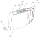
FIG. 1 is a schematic view of an anvil receptacle according to an embodiment of the present invention.
FIG. 2 is a schematic view showing the state where the anvil is withdrawn in the embodiment of the present invention.
Fig. 3 is a schematic drawing showing the drawn-out state of the anvil frame of the second assembly in the embodiment of the present invention.
FIG. 4 is a schematic view showing the draining tank in the embodiment of the present invention.
Figure 5 is a schematic view of the anvil receptacle in a flat position according to an embodiment of the present invention.
Figure 6 is a schematic view of the anvil receiver after the anvil is withdrawn according to the embodiment of the present invention.
Fig. 7 is a schematic view of an internal structure of the anvil receptacle according to the embodiment of the present invention.
FIG. 8 is a second schematic view of the internal structure of the anvil receptacle according to the embodiment of the present invention.
Figure 9 is a third schematic view of the interior structure of the anvil receptacle of the present embodiment of the invention.
Figure 10 is a fourth schematic view of the interior of the anvil receptacle of the present embodiment of the invention.
Figure 11 is a schematic view of the anvil structure of the present invention.
Detailed Description
The name of the product is an anvil plate receiver with disinfection and sterilization functions, and also can be called an anvil plate disinfector, an anvil plate receiver, an anvil plate sterilizer and the like, the specific name does not limit the protection scope, and the specific protection scope is subject to the claims.
As shown in fig. 1 to 11, the cutting board container of the present patent mainly comprises the following components: a first component cutting board container base 100, a UV ultraviolet lamp 101, a reflecting surface 102, a magnetic adsorption mechanism 103 of the first component, a separation through hole 104, a power supply control module 105, an ultraviolet light leakage prevention mechanism 106, a remote control module 107, a draining groove 108, a fan 109, a stabilizing support or a sucker 110; a second assembly anvil frame 200, an anvil receiving groove 201, an anvil frame magnetic adsorption part 202, an anvil frame shock absorption part 203, a cutter or chopstick receiving groove 204, and a limit block 205; a third component anvil 300, an anvil knob 301, and a knob anti-slip feature 302.
As can be seen from fig. 1 to 11, in one embodiment, the first component cutting board container base 100 is a square structure, and the UV lamp 101 and the power control module 105 are both disposed at an end of one side of the first component cutting board container base 100. A second component anvil frame 200 is provided within the cavity of the anvil container base 100, the anvil frame 200 is provided with an anvil receiving slot 201 and a knife and chopstick receiving slot 204. The top of ware base 100 is accomodate to the chopping block is provided with the switch, and after the appointed station of groove 201 is accomodate to the chopping block that puts into chopping block frame 200 when third subassembly chopping block 300, starting switch can utilize UV ultraviolet lamp 101 to disinfect chopping block 300, if take out chopping block 300 midway, then UV ultraviolet lamp 101 can stop work. The chopping board storage groove 201 is an open storage groove in both the vertical direction and the horizontal direction, and a user can take and place the chopping board 300 at any angle between the vertical direction and the horizontal direction. Further, the anvil frame 200 may also be removable for cleaning. It can be seen from fig. 5 that the anvil frame 200 may be provided with a grid-like hollowed-out structure. In fig. 6, it can be seen that the uv light leakage prevention mechanism 106 is disposed at the diagonal of the bottom corner of the first component anvil receiver base 100, the uv light leakage prevention mechanism 106 can be a micro switch, and in fig. 6, the anvil frame shock absorbing part 203 can also be seen. The cutter receiving groove and the chopstick receiving groove may be a single cutter or chopstick receiving groove 204 that is reused because the diameter of the chopstick is as much as the thickness of the cutter.
The specific product structure and the working principle are further described in detail below.
As can be seen from fig. 1-11, the main components of the product described in this patent are a first component anvil receptacle base 100, a second component anvil frame 200, and a third component anvil 300.
A UV ultraviolet lamp tube and a power module are arranged in the chopping board container base 100. The top of the anvil sterilizer base 100 is largely omitted, as is one side of the base, i.e., there is no need for a separate housing or cover to cover both sides. Preferably, once the second component anvil frame 200 is placed into the cavity of the anvil receptacle base 100, the connection position between the anvil frame 200 and the anvil receptacle base 100 at the top and the side is a substantially airtight or tightly attached connection, which is equivalent to directly forming the top and the side wall of the anvil receptacle. It should be emphasized that the "close and tight fit" connection means not absolute 100% sealing or closing, nor necessarily 100% fit, but in this patent, it is mainly sufficient that the gap at the connection portion is small, so that the ultraviolet light does not leak basically, and is ensured within a safe numerical range.
Preferably, the anvil frame 200 is detachably connected to the anvil receptacle base 100, such as by magnetic attraction or snap-lock. Preferably, the first component cutting board container base is connected with the cutting board through magnetic adsorption.
This patent product includes UV ultraviolet lamp 101 UV lamp 101 sets up in chopping block storage device base 100 side tip, preferably adopts U type fluorescent tube, at least one also can adopt L ED's UV lamp, because led's UV lamp volume is less, consequently can install on a plurality of sides of base inner wall, can make product thickness less for it is more comprehensive to shine UV light, but the cost of the UV lamp of L ED at present is higher, also can adopt many straight UV lamps, be this patent protection scope.
The U-shaped ultraviolet lamp tube is usually used for irradiating the escherichia coli for 30s with 5-20W of power, generally 10-15W of UV lamp can kill the escherichia coli, and about 15 minutes may be needed for other bacteria. U type ultraviolet lamp sets up the side tip of accomodating the ware at the chopping block, U type fluorescent tube corresponds and sets up light-transmitting opening, and light-transmitting opening corresponds and is provided with the chopping block to, the ultraviolet ray on U type radian No. limit can shine cutter or chopsticks that the centre set up and accomodate in the groove 204 cutter or chopsticks.
Preferably, the UV lamps 101 are arranged on the side of the anvil frame 200, meaning that the UV lamps 101 are not arranged frontally with respect to the anvil surface. Of course, the UV ultraviolet lamp also can set up the positive surface at the chopping block, and whole chopping block storage device product will become than thicker like this, and the quantity of the UV lamp that needs simultaneously is more, because the chopping block needs two-sided sterilization, the UV lamp sets up at side tip, then the UV lamp of a U type can be for the disinfection of disinfecting simultaneously of a plurality of faces of polylith chopping block.
The anvil receiver product of the present patent further includes a reflective surface 102. Preferably, this patent adopts multi-angle plane of reflection technical scheme. In one embodiment, since the cutting board 300 is a sheet-like shape, and the cutting board storage is generally designed to have a book-shaped square structure in order to reduce the size, the UV lamp 101 is preferably disposed at an end portion of a side surface of the cutting board storage. In order to make the UV lamp irradiate the surface of the cutting board more fully, the present patent provides one or more reflecting surfaces 102, such as a mirror or a metal reflector or an electroplated reflector, on the inner surface of the base 100 of the cutting board container or on the cutting board frame 200. For example, one or more reflective surfaces 102 can be provided on the inner wall of the anvil receptacle on two or/and three sides of the inner surface.
Preferably, the reflective surface 102 has a certain inclination angle or arc of reflection for better reflection. Preferably, the anvil frame 200 is configured with a partially hollowed-out structure, such as a hollowed-out grid frame structure, as shown in fig. 3-5, to facilitate the ultraviolet light to pass through the anvil frame 200, and further facilitate multiple reflection irradiation of the anvil 300 and the cutting tools. The plurality of reflecting surfaces 102 are arranged, so that multi-angle multi-time reflection is facilitated, the chopping board and the cutter are subjected to omnibearing sterilization and disinfection, and the sterilization and disinfection effects of ultraviolet light are improved.
Preferably, the product comprises a magnetic attachment or snap lock connection mechanism 103 of the first component. The first component chopping board receiver base 100 and the second component chopping board frame 200 are in magnetic adsorption or buckle locking connection; there is magnetic attraction between the second assembly anvil frame 200 and the anvil 300.
To the technical scheme that anvil frame 200 and anvil receptacle base 100 adopt the magnetism to adsorb the mode of can dismantling and be connected, first component anvil receptacle base 100 is provided with the separation through-hole 104 that is used for the separation of anvil frame 200. The bottom of chopping block container base sets up separation through-hole 104 and is the through-hole structure, is convenient for push away chopping block frame 200 with the through-hole structure that the finger can directly pass the fretwork and is connected with the magnetism adsorption of chopping block container base 100 to utilize the separation through-hole structure of minimality, low cost to promote the convenience that the user took out chopping block frame. Further, the cutting board rack extraction structure is disposed at an end remote from the bottom draining tank 108.
The first component cutting board container base 100 includes a power control module 105, and the power control module 105 includes a circuit structure and a switch. The circuit structure can further comprise a control chip and a wifi module or a Bluetooth module, so that automatic cycle working control or remote monitoring and control can be better realized. The product is provided with a key starting switch, can make the UV ultraviolet lamp 101 of chopping block storage device carry out regularly disinfection work, and operating duration can set up as required to 5 minutes ~ 20 minutes, preferred 10 minutes ~ 15 minutes. Further, the chopping board storage device can automatically and circularly sterilize, the UV ultraviolet lamp sterilization work can be automatically started every 3-4 hours according to needs, 15-30 minutes are carried out every time, and the sterilization effect is further optimized.
Preferably, the power control module 105 is disposed at the end of the side of the base of the chopping board container, so that the chopping board container is safer, waterproof and not easy to damage, and particularly, the circuit structure is not disposed at the bottom of the base of the chopping board container. The circuit structure and the UV ultraviolet lamps 101 are all arranged at the end part of the side face of the base of the chopping board container, the switch is arranged at the top of the end part of the side face of the base, and the cavity with the opening at the other side of the base opened is used for placing the chopping board frame 200 and the chopping board 300. Just so can realize the "wet-dry separation" that the chopping block was accomodate, because, on the one hand, in the chopping block 300 use, often take water work, and what probably wipe when putting into chopping block frame 200 does not do, still take water, these water can flow on chopping block frame 200's lower part and chopping block accommodator base, on the other hand, chopping block frame 200 can set up magnetic adsorption mode or buckle locking connection mode with chopping block accommodator base 100 as required, easily can not dismantle directly fast with any other instrument and wash, and chopping block accommodator lower part ponding easily, and in the use, probably can wipe with wet rag, therefore circuit system arranges at side tip, and is safer.
In a preferred embodiment, the product further comprises an ultraviolet light leakage prevention mechanism 106, and the ultraviolet light leakage prevention mechanism 106 may be a micro switch or an infrared sensor. In actual use, a switch can be started due to misoperation including but not limited to that a child randomly presses a button, or a cutting board rack is not placed at a specified station or a cutting board is not placed at a specified station, so that UV ultraviolet light leaks, and certain safety problems are caused. In order to prevent UV leakage or child mishandling, it is necessary to provide a mechanism for preventing UV light leakage in the product of this patent. The ultraviolet light leakage prevention mechanism 106 may be a micro switch or an infrared sensor, and the specific setting position of the ultraviolet light leakage prevention mechanism 106 is also selective, so how to implement such functions by adopting a simpler and safer structure is challenging, and several technical solutions are introduced as follows.
One technical solution of the mechanism 106 for preventing ultraviolet light leakage is to use a micro switch, which is a contact mechanism having a minute contact interval and a quick action mechanism and performing a switching action with a predetermined stroke and a predetermined force, and a switch having a driving lever outside thereof, because the contact interval of the switch is relatively small, the micro switch is called a sensitive switch. The external mechanical force acts on the action reed through a transmission element (a press pin, a button, a lever, a roller and the like), and when the action reed is displaced to a critical point, instantaneous action is generated, so that a movable contact at the tail end of the action reed is quickly connected with or disconnected from a fixed contact.
In view of, it is not suitable for being provided with the circuit on chopping block frame 200, because chopping block frame 200 probably will dismantle and take out the washing, consequently, a solution of this patent is, micro-gap switch sets up on chopping block storage device base 100, corresponding chopping block frame 200 is close to chopping block storage device base position department and sets up to hollow out construction, when its purpose places chopping block frame 200 appointed station for chopping block 300, the edge of chopping block 300 can see through the micro-gap switch that chopping block frame 200's hollow out construction contacted chopping block storage device base 100 base position department and set up, thereby make the product can normally work, start the UV ultraviolet. If chopping block 300 has not inserted appointed station and/or chopping block frame 200 has not placed appointed station, can all lead to the unable micro-gap switch that contacts chopping block storage device base angle department setting in edge of chopping block 300, the unable normal work of product, has a UV work pilot lamp this moment can red or flash the warning, and stop work, when the consumer took out chopping block 300, also can automatic stop work. The structure is ingenious, the cost is low, and the product safety is effectively improved.
Preferably, a first microswitch is arranged between the cutting board container base 100 and the cutting board 300, and the cutting board can normally work when placed at a designated station. Preferably, a second micro switch is provided between the anvil receptacle base 100 and the anvil frame 200, and when the anvil frame 200 is placed at a designated station, the normal operation is possible. Preferably, when the anvil plate 300 is placed at a designated station and when the anvil plate frame 200 is also placed at the designated station, the first and second micro switches can normally operate at the same time, and the whole product can operate.
Another technical solution of the ultraviolet light leakage preventing mechanism 106 is to use an infrared sensor, preferably an infrared sensor disposed at the bottom of the base, similar to the position of the micro switch, and also to set a plurality of infrared sensors, to monitor whether the chopping board frame 200 is placed at a designated station, and to monitor whether the chopping board 300 is placed at a designated station, and only after the chopping board and the chopping board frame are placed at the designated station, the product can normally work.
The diagonal position of the bottom corner of anvil receiver base 100 is the preferred location for placement of uv light leakage prevention mechanism 106.
If the anvil frame 200 is a non-detachable structure, it is only necessary to monitor whether the anvil 300 is in place.
The product further includes remote control module 107, can increase bluetooth module or Wi-Fi module in the product as remote control module 107, can be connected to the network like this to carry out remote control through mobile terminal APP, for example the App on the cell-phone controls, remote control product work, the remote after being convenient for get off duty, travel home starts work of disinfecting in advance. Further, the power control module comprises a related chip, the disinfection frequency of the chopping board can be counted, when the specified frequency is reached, for example 2000 times, the disinfection frequency is fed back to the mobile terminal or the product to display that the chopping board is due and should be replaced, so that a user is reminded to replace the new chopping board at intervals, and a healthier life style is provided.
The bottom of the cutting board receiver base 100 is provided with a drip trough 108, which is disposed at the bottom, either entirely or partially within the length of the bottom. The bottom of the chopping board container base can be slightly inclined with the position of connection of the draining groove 108, so that better draining is facilitated. The drip trough 108 is connected to the cutting board receiver base 100 by a magnetic attachment structure. Preferably, the magnetic adsorption structure of the draining tank 108 and the cutting board container base 100, and the magnetic adsorption structure of the cutting board container base 100 and the cutting board 300 can share part of the magnetic adsorption part; or the magnetic adsorption structure of the draining groove 108 and the cutting board container base 100, the magnetic adsorption structure of the cutting board frame 200 and the cutting board 300 can be a part of magnetic adsorption parts, so that the structure is further simplified, and the cost is reduced.
The bottom of the chopping block frame 200 is of a hollow frame structure or is provided with water leakage holes, and the partial area can be provided with the water leakage holes, and further, the bottom plate of the chopping block frame 200 is slightly inclined, so that water flows downstream to the water leakage holes or the water leakage port, and the volume of the chopping block draining groove 108 is reduced. Preferably, the draining groove 108 occupies only 30% -50% of the length of the bottom of the anvil receiver base, and the other side of the bottom of the anvil sterilizer base 100 is provided with an opening structure, i.e., a separation through hole 104, through which the anvil frame 200 is taken out.
The bottom of the chopping board container base 100 further comprises a stabilizing support or a suction cup 110, so that the chopping board container is more stable to place on the table top and is not easy to topple. Furthermore, the stabilizing support at the bottom of the chopping board container base 100 is of a telescopic structure, and can rotate or extend to extend out for a certain angle, so that the support is more stable; or the suction cups are plural.
This patent the chopping block storage device includes second subassembly chopping block frame 200, second subassembly chopping block frame 200 with the connected mode between first subassembly chopping block storage device base 100 is the shaping mode of integration, perhaps the detachable mode of bolt screw fixation, perhaps for the detachable connected mode of magnetism absorption or buckle locking.
The anvil frame 200 and the anvil receiver base 100 are fixed by bolts and screws, and when the anvil frame is detached, tools such as a screwdriver are needed.
One design scheme of the product of this patent does: the direct opening in cavity top of ware base 100 is accomodate to the chopping block is opened, does not have the extra lid that shelters from the ultraviolet light, and the station is directly placed into from the top of ware base 100 cavity is accomodate to the chopping block to second subassembly chopping block frame 200 like this, and is corresponding, is provided with chopping block on the chopping block frame and accomodates groove 201, and chopping block 300 can be accomodate groove 201 from the chopping block at the top of ware base 100 and directly places into the station, and the consumer can directly get in vertical direction and put the chopping block to and chopping block frame. The contact of the anvil frame 200 with the anvil container base 100 and the anvil 300 at the top and the outside communicating portion is a close fitting connection or a substantially airtight connection, which plays a role of preventing most of the ultraviolet light from leaking, and a cover covering the anvil container groove is not separately provided in this embodiment.
Another design scheme of the product of the patent is as follows: the direct opening of side tip of chopping block container base 100 is opened, there is not the extra lid that shelters from the ultraviolet light, the station is directly placed into to the side tip that the cavity of chopping block container base 100 can be followed to second subassembly chopping block frame 200 like this, it is corresponding, be provided with the chopping block on the chopping block frame and accomodate groove 201, chopping block 300 can accomodate groove 201 from the chopping block of side tip of chopping block container base 100 and directly place the station into, the consumer can directly get on the horizontal direction and put the chopping block, and the chopping block frame. The contact of the anvil frame 200 with the anvil container base 100 and the anvil 300 at the side end portions with the outside communicating portion is a close fit connection or a substantially airtight connection, which plays a role of preventing most of the ultraviolet light from leaking.
The product of this patent still has a preferred design scheme to, the product design time adopts dual ergonomic design, on one hand, the top and side tip of the chopping block frame 200 directly open at the same time and open the chopping block that is designed as the wider accepting angle and take in the groove 201, there is not the cover which shelters from the ultraviolet light alone, therefore the user can take out or place the chopping block 300 from the chopping block and take in the groove in the way that the user is accustomed to directly in any angle direction between vertical direction and horizontal direction, accord with ergonomic design, easy to use, the required space of action when the user gets and puts the chopping block is also smaller; on the other hand, the design is opened to the direct opening simultaneously of the cavity top and the side tip of chopping block storage device base 100, does not have the extra lid that shelters from the ultraviolet light, and second subassembly chopping block frame 200 is the connection of dismantling of magnetic adsorption mode, and the user can directly get from the arbitrary angle direction between the vertical direction of the cavity of chopping block storage device base 100 and the horizontal direction and put at will to dismantle cleanly, further accord with ergonomic design.
In order to promote user experience, optimize the product structure, further save product manufacturing cost, this product is not designed into a casing like traditional product, places ultraviolet degassing unit, chopping block frame and chopping block in the casing in all, then in order to prevent that the ultraviolet ray from leaking the extra lid that sets up again and seal.
One kind technical scheme in this patent has cancelled the design that sets up the lid that prevents the ultraviolet light leakage alone, and the position of being connected of chopping block frame 200 and chopping block 300 and chopping block frame 200 and chopping block container base 100 of this patent all design into "airtight connection relation", prevent that the UV ultraviolet light from leaking. "airtight connection relation" in this patent refers to the close fitting connection relation, "airtight connection relation or close fitting connection, airtight connection or sealing connection" in this patent are not absolute complete vacuum seal or vacuum seal, and its main finger can play and make most UV ultraviolet light basically not leak can. The gap between the second component chopping board frame and the first component chopping board container base at the inlet connecting part of the open cavity is 0-1 mm, preferably 0-0.5 mm; the entrance of groove is accomodate to the chopping block of second subassembly chopping block frame and the clearance of chopping block edge connecting portion is 0 ~ 1 millimeter, preferably 0 ~ 0.5 millimeter. The sealing effect is better if the gap or clearance between the connecting portions of the anvil frame 200 and the anvil 300 and the gap clearance between the connecting portions of the anvil frame 200 and the anvil container base 100 are controlled to be as small as about less than 0.5 mm as possible, and the diffusion of UV light is basically ensured within a safe numerical range. If other structural design schemes of the patent are adopted and finally a cover is added, the protection scope of the patent is also considered.
The dual ergonomic design described in this patent: in the first aspect, the unique opening design of the chopping board frame 200 enables the chopping board 300 to be freely taken and placed at any angle between the vertical angle and the horizontal angle of the chopping board frame 200, so that the design is more in line with the ergonomic design, the user experience can be greatly improved, and the chopping board frame is suitable for different use habits of people with different heights; in the second aspect, the chopping board frame 200 can be freely taken and placed at any angle from the vertical angle to the horizontal angle of the chopping board frame storage base 100, and is more favorable for disassembly, cleaning, manufacturing and raw material saving.
The position that corresponds with the UV ultraviolet lamp on the chopping block frame 200 is provided with the light trap, and chopping block frame 200 sets up to whole structural style that can dismantle on the chopping block container base and take out. Preferably, the chopping block frame is made into a hollow structure, so that the chopping block frame is more beneficial to light transmission; on one hand, the structure is not easy to deform and is similar to a reinforcing rib structure; on one hand, the material can be saved, and the weight of the product can be reduced.
When chopping block 300 and chopping block frame 200 were put into appointed station, the chopping block edge formed the airtight relation of closely laminating with the edge of chopping block storage groove, and it is mainly in order to prevent the leakage of UV ultraviolet ray, certainly this patent closely laminating or airtight or sealed also be absolute 100% airtight or sealed, probably still have less clearance between the part, but can play isolated most ultraviolet effect can, guarantee safe in utilization can. Preferably, the chopping block frame is provided with a plurality of chopping block and accomodates the groove, can accomodate the polylith chopping block. Preferably, the anvil frame and the anvil receptacle base are of a magnetically-attached detachable construction.
Preferably, be provided with one or more magnetism on chopping block frame and/or the chopping block storage device base and adsorb the part, can adsorb the cutter, prevent that the cutter from droing, perhaps can adsorb the chopping block, the chopping block corresponds the position this moment and need be provided with magnetism and adsorb the part. Preferentially, be provided with one or more magnetism on the chopping block storage device base and adsorb the part, can adsorb the chopping block frame on the one hand, on the other hand can adsorb cutter and/or chopping block, and magnetism adsorbs the part can share like this, and further reduce cost simplifies the structure, improves production efficiency.
Of course, the chopping block frame and the chopping block storage device base can also adopt a conventional buckle clamping mode or a limiting block mode or a screw connection mode and the like, and the use is not convenient like magnetic adsorption.
Further, the anvil frame 200 includes an anvil frame cushioning component 203. Because the chopping block has certain weight, when the chopping block was put into the chopping block frame, under the effect of gravity or magnetic attraction, the chopping block can strike the chopping block frame usually, can produce the noise sound on the one hand, and long-term striking of on the other hand can lead to the product to damage. In order to solve the problems, on one hand, the multi-angle picking and placing structure design conforming to human engineering is adopted, so that the picking and placing of consumers are facilitated, the using space is saved, the consumers can also push and place the glass from the side surface when placing the glass, and the glass is not easy to generate impact; on the other hand is provided with chopping block frame shock absorber part 203 in the bottom of chopping block frame and/or side tip, plays the buffering effect of moving away to avoid possible earthquakes, reduces the noise when the chopping block is put into, promotes product life, chopping block frame shock absorber part 203 can be for comparatively soft cubic or banding silica gel or rubber material etc..
Further, a cutter or chopstick receiving groove 204 is formed at the top of the second assembly anvil frame 200; the notch in cutter or chopsticks holding groove is provided with stopper 205, stopper 205 is the slider that can fasten, stopper 205 can move along the notch, can expand the cutter that is fit for different size of a dimension or the chopsticks of different quantity. The device is beneficial to limiting the cutter or the chopsticks and preventing the cutter or the chopsticks from falling off; a further sliding block is provided with a fastening device, such as a fastening screw, so that the limiting is facilitated. When the cutter is put in, a cutter clamping structure can be arranged on the inner side of the cutter accommodating groove so as to fasten the cutter.
This patent product includes third subassembly chopping block 300, the chopping block is two-sided chopping block, including the knob portion 301 of chopping block, knob portion 301 sets up the diagonal apex angle position on two limits of chopping block, cooperates the multi-angle that this patent accords with ergonomic to get and puts structural design, and the consumer can follow the vertical direction of chopping block container and take out the chopping block to the arbitrary angle of horizontal direction, accords with ergonomic on the one hand like this, gets and puts easily, on the other hand, most kitchen space is limited, requires littleer to the usage space in the aspect of this patent.
The front and back surfaces of the knob part 301 of the chopping board are provided with knob part anti-slip parts 302, and the front and back surfaces are marked with different marks, such as characters or patterns of vegetables, fish, fruits and the like, and correspond to different purposes of the chopping board, so that a consumer can conveniently select a specific chopping board. The texture of the two sides of the chopping block is different, the function classification is different, for example, characters or patterns of vegetables, fish, fruits and the like correspond to different textures.
The anti-slip pads on the front and back sides are arranged at 4 corners of the chopping board, so that the chopping board can be fixed conveniently when in use; meanwhile, a circle of shallow splash-proof water tank is arranged at the position, close to the edge, of the surface of the chopping board, so that vegetable washing water and the like on the surface of the chopping board can be guided conveniently.
The chopping board can be made of high polymer resin materials, for example, food-grade ABS, PP and other high polymer resin materials with different colors are adopted; the wood-plastic composite material can also be made of raw wood, bamboo, composite wood and other materials, or a composite material of wood and plastic and the like.
Preferably, the chopping block is multilayer composite construction, and the colour of surface course material is different with the colour of inlayer material, and the consumer can have cutting wearing and tearing in daily use, and when the top layer was worn and torn to certain extent by the cutting, will expose the different colour of inlayer, just so can indicate the consumer to change the cutting board of new, more be favorable to promoting consumer user experience, the regular replacement chopping block of being convenient for, it is safer.
Another technical solution is a chopping block container, which includes a stabilizing support or a supporting portion in the horizontal direction, the structures of the chopping block frame 200 and the chopping block container base 100 are the same as those of the other embodiments of the present patent, but the chopping block frame 200 and the chopping block container base 100 are disposed at an inclined angle. For example, the chopping block container is placed on the table top through a stabilizing support or a supporting part, the chopping block frame 200 and the chopping block container base 100 are integrally inclined by 30-45 degrees relative to the horizontal plane of the table top, the notch of the chopping block containing groove also presents an inclined angle, when the chopping block containing groove of the chopping block frame is placed in the chopping block, the chopping block can automatically slide to a designated station along the notch of the inclined chopping block containing groove under the action of self gravity, the designated station is also more favorably placed, and ultraviolet light leakage is prevented. Compare in the notch in the chopping block of vertical direction and accomodate the groove, the notch of slope plays the cushioning effect, is difficult for taking place the condition of chopping block direct impact chopping block grillage bottom, accomodates the notch in groove for the chopping block of horizontal direction, need not the whole propelling movement of user and appoints the station, only needs the user to put into the notch in chopping block accomodating groove after, can automatic sliding target in place, user experience is good.
The utility model provides a technical scheme, chopping block frame 200 surface is fretwork or not fretwork, and the top and/or the side tip of chopping block frame 200 set up the chopping block and accomodate groove 201, in the chopping block accomodates groove 201 and chopping block 300 all is provided with the magnetic adsorption part, and both magnetic adsorption connect, and chopping block frame 200 can sell and use alone with chopping block 300.
It should be noted that the structures and parameters described in the above embodiments are only for illustrating the implementation state of the present invention.
The above description is only for the preferred embodiment of the present invention and is not intended to limit the scope of the present invention, and all equivalent structural changes made by using the contents of the present specification and the drawings are included in the scope of the present invention.
Claims (13)
1. The utility model provides a ware is accomodate to chopping block with disinfection function which characterized in that:
the cutting board storage device comprises a first component cutting board storage device base and a second component cutting board frame, wherein the first component cutting board storage device base is provided with a UV (ultraviolet) lamp and a power supply control module, the second component cutting board frame is provided with a light hole, and ultraviolet light of the UV lamp can irradiate the surface of a cutting board in the cutting board frame through the light hole;
the top of the first component chopping board container base is provided with an open-ended cavity, and a second component chopping board frame is arranged in the open-ended cavity;
the top of second subassembly chopping block frame is provided with at least one chopping block and accomodates the groove, the chopping block is accomodate the groove and can be taken out or put into the chopping block in the vertical direction of chopping block frame, perhaps, the side tip of second subassembly chopping block frame is provided with at least one chopping block and accomodates the groove, the chopping block is accomodate the groove and can be taken out or put into the chopping block at the horizontal direction of chopping block frame.
2. The chopping board container with disinfection and sterilization functions as claimed in claim 1, wherein: the inlet of the chopping block accommodating groove of the second component chopping block frame is tightly attached and connected with the chopping block;
the second component chopping board frame and the first component chopping board container base are closely attached and connected at the inlet connecting part of the open cavity.
3. The chopping board container with disinfection and sterilization functions as claimed in claim 1, wherein: the bottom or the side of the first component chopping board container base is provided with a through hole, and the first component chopping board container base can be pushed to be separated from the second component chopping board frame through the through hole.
4. The chopping board container with disinfection and sterilization functions as claimed in claim 1, wherein: and a cover is arranged at the notch of the chopping block accommodating groove of the second component chopping block frame.
5. The chopping board container with disinfection and sterilization functions as claimed in claim 1, wherein: for the magnetism adsorbs between first subassembly chopping block container base and the second subassembly chopping block frame and is connected, or for the magnetism adsorbs between second subassembly chopping block frame and the chopping block and is connected, or for the magnetism adsorbs between first subassembly chopping block container base and the chopping block and is connected.
6. The chopping board container with disinfection and sterilization functions as claimed in claim 1, wherein: the second component chopping block frame with the connected mode between the first component chopping block container base is bolt and screw fixed connection mode, perhaps, second component chopping block frame and first component chopping block container base are the integrated into one piece structure.
7. The chopping board container with disinfection and sterilization functions as claimed in claim 1, wherein: the gap between the second component chopping board frame and the first component chopping board container base at the inlet connecting part of the open cavity is 0-1 mm; the entrance of the chopping block accommodating groove of the second component chopping block frame and the gap of the chopping block edge connecting part are 0-1 mm.
8. The chopping board container with disinfection and sterilization functions as claimed in claim 1, wherein: the second assembly chopping block frame is provided with 2 chopping block accommodating grooves; a cutter or chopstick accommodating groove is arranged between the 2 chopping board accommodating grooves;
UV ultraviolet lamp and power control module set up the side tip at first subassembly chopping block storage device base inner wall, power control module includes circuit structure and switch, the UV lamp adopts U type ultraviolet fluorescent tube or rectangular form fluorescent tube, the ultraviolet light energy of UV ultraviolet lamp shines cutter or the chopsticks between 2 chopping blocks storage groove through the light trap and accomodates the groove.
9. The chopping board container with disinfection and sterilization functions as claimed in claim 1, wherein: at least one reflecting surface is arranged on the inner surface of the base of the first component chopping board container or the chopping board frame, and the reflecting surface is a mirror or an electroplating reflecting board;
the reflecting surface is arranged at an inclined angle relative to the UV lamp, or the reflecting surface is of an arc-shaped structure.
10. The chopping board container with disinfection and sterilization functions as claimed in claim 1, wherein: be provided with first micro-gap switch or infrared sensor in the ware base is accomodate to first subassembly chopping block, can trigger first micro-gap switch or infrared sensor when the chopping block is put into the appointed station of second subassembly chopping block frame, the ware is accomodate to the chopping block can normally work.
11. The chopping board container with disinfection and sterilization functions as claimed in claim 10, wherein: the first microswitch is arranged at the bottom corner of the base of the first component chopping board container, the second component chopping board frame is arranged to be a hollow structure at the bottom corner close to the base of the chopping board container, and when a chopping board is placed at a station appointed by the second component chopping board frame, the edge of the chopping board can pass through the hollow structure of the second component chopping board frame to contact the first microswitch arranged at the bottom corner of the base of the first component chopping board container, so that the chopping board container can work normally;
or, second subassembly chopping block frame with connected mode between the first subassembly chopping block container base is for dismantling the connection, be provided with first micro-gap switch between first subassembly chopping block container base and the chopping block, be provided with second micro-gap switch between first subassembly chopping block container base and the second subassembly chopping block frame, when the second subassembly chopping block frame appoints the station when the chopping block is placed to when the second subassembly chopping block frame also places first subassembly chopping block container base appointed station, first micro-gap switch and second micro-gap switch could trigger, and chopping block container normally works.
12. The chopping board container with disinfection and sterilization functions as claimed in claim 1, wherein: the first component chopping board container base comprises a wifi module or a Bluetooth module, the wifi module or the Bluetooth module can be connected with a mobile terminal, and the chopping board container is started or closed through the mobile terminal; a water leaching groove is formed in the bottom of the first component cutting board container base and is connected with the first component cutting board container base through a magnetic adsorption structure; a fan is arranged at the end or the side surface of the chopping board container base; the bottom of the chopping board container base is provided with a support, or the bottom of the chopping board container is provided with at least one sucker; one or more shock absorbing components are disposed at the bottom and/or side ends of the second assembly anvil frame.
13. The chopping board container with disinfection and sterilization functions as claimed in claim 1, wherein: the top of second subassembly chopping block frame is provided with cutter or chopsticks and accomodates the groove, the notch that cutter or chopsticks accomodate the groove is provided with the stopper, the slider that the stopper can be set up, the stopper can be followed the notch and removed, can expand suitable not unidimensional cutter or chopsticks.
Priority Applications (1)
| Application Number | Priority Date | Filing Date | Title |
|---|---|---|---|
| CN201910089989.0A CN111493709A (en) | 2019-01-31 | 2019-01-31 | Chopping block storage device with disinfection function |
Applications Claiming Priority (1)
| Application Number | Priority Date | Filing Date | Title |
|---|---|---|---|
| CN201910089989.0A CN111493709A (en) | 2019-01-31 | 2019-01-31 | Chopping block storage device with disinfection function |
Publications (1)
| Publication Number | Publication Date |
|---|---|
| CN111493709A true CN111493709A (en) | 2020-08-07 |
Family
ID=71848115
Family Applications (1)
| Application Number | Title | Priority Date | Filing Date |
|---|---|---|---|
| CN201910089989.0A Pending CN111493709A (en) | 2019-01-31 | 2019-01-31 | Chopping block storage device with disinfection function |
Country Status (1)
| Country | Link |
|---|---|
| CN (1) | CN111493709A (en) |
Cited By (1)
| Publication number | Priority date | Publication date | Assignee | Title |
|---|---|---|---|---|
| EP4356799A1 (en) * | 2022-10-20 | 2024-04-24 | Caraway Home, Inc. | Culinary container storage device |
-
2019
- 2019-01-31 CN CN201910089989.0A patent/CN111493709A/en active Pending
Cited By (1)
| Publication number | Priority date | Publication date | Assignee | Title |
|---|---|---|---|---|
| EP4356799A1 (en) * | 2022-10-20 | 2024-04-24 | Caraway Home, Inc. | Culinary container storage device |
Similar Documents
| Publication | Publication Date | Title |
|---|---|---|
| CN210204539U (en) | Chopping block storage device with disinfection function | |
| CN111493709A (en) | Chopping block storage device with disinfection function | |
| CN201192289Y (en) | Chopsticks cage | |
| CN111493708A (en) | Ware and categorised chopping block are accomodate to domestic healthy categorised chopping block | |
| CN210204537U (en) | Categorised chopping block storage device with ultraviolet sterilization function | |
| CN210204527U (en) | Categorised chopping block storage device | |
| CN210204538U (en) | Ware and categorised chopping block are accomodate to domestic healthy categorised chopping block | |
| KR20160002642U (en) | Sterilizing Container for Spoons and Chopsticks | |
| KR20110004039U (en) | Multi-funtional sterilization case | |
| KR20080006326A (en) | Sterilization devive for kitchen utensils | |
| CN111493710A (en) | Categorised chopping block storage device with ultraviolet sterilization function | |
| CN111493699A (en) | Categorised chopping block storage device | |
| KR101483032B1 (en) | Container case for kitchen utensil | |
| CN210871412U (en) | Control panel of dish-washing machine and dish-washing machine | |
| CN202168961U (en) | Disinfection cup | |
| CN215534154U (en) | Assembled knife and chopsticks sterilizer | |
| CN201234925Y (en) | Dehydration chopping board | |
| CN212880208U (en) | Waterproof knife and chopstick sterilizer | |
| CN215738795U (en) | Tableware placing unit and dish washing machine | |
| CN215738782U (en) | Tableware cleaning unit and dish washing machine | |
| CN214074341U (en) | Sterilizing device for sterilizing chopping blocks, chopsticks and cutters | |
| CN215076778U (en) | Hotel's food and beverage is with categorised strorage device of tableware | |
| CN220530383U (en) | Multifunctional knife chopstick sterilizing rack | |
| CN215424276U (en) | Kitchen utensils purifying device | |
| CN211129993U (en) | Tableware box with disinfection function |
Legal Events
| Date | Code | Title | Description |
|---|---|---|---|
| PB01 | Publication | ||
| PB01 | Publication | ||
| SE01 | Entry into force of request for substantive examination | ||
| SE01 | Entry into force of request for substantive examination | ||
| TA01 | Transfer of patent application right |
Effective date of registration: 20221207 Address after: Room 904-1, Shishan Science and Technology Museum, No. 105, Dengwei Road, high tech Zone, Suzhou, Jiangsu 215000 Applicant after: Suzhou xinqingsong Intelligent Technology Co.,Ltd. Address before: Room 515, building 2, northwest Suzhou nano City, 99 Jinjihu Avenue, Suzhou Industrial Park, 215000, Jiangsu Province Applicant before: Suzhou Quanmi City Intelligent Technology Co.,Ltd. |
|
| TA01 | Transfer of patent application right |