CN111483942A - Moving device for welding steel pipes of steel pipe tower - Google Patents
Moving device for welding steel pipes of steel pipe tower Download PDFInfo
- Publication number
- CN111483942A CN111483942A CN202010357918.7A CN202010357918A CN111483942A CN 111483942 A CN111483942 A CN 111483942A CN 202010357918 A CN202010357918 A CN 202010357918A CN 111483942 A CN111483942 A CN 111483942A
- Authority
- CN
- China
- Prior art keywords
- fixed frame
- welding
- steel tube
- steel pipe
- arc
- Prior art date
- Legal status (The legal status is an assumption and is not a legal conclusion. Google has not performed a legal analysis and makes no representation as to the accuracy of the status listed.)
- Granted
Links
Images


Classifications
-
- B—PERFORMING OPERATIONS; TRANSPORTING
- B66—HOISTING; LIFTING; HAULING
- B66F—HOISTING, LIFTING, HAULING OR PUSHING, NOT OTHERWISE PROVIDED FOR, e.g. DEVICES WHICH APPLY A LIFTING OR PUSHING FORCE DIRECTLY TO THE SURFACE OF A LOAD
- B66F7/00—Lifting frames, e.g. for lifting vehicles; Platform lifts
- B66F7/10—Lifting frames, e.g. for lifting vehicles; Platform lifts with platforms supported directly by jacks
- B66F7/12—Lifting frames, e.g. for lifting vehicles; Platform lifts with platforms supported directly by jacks by mechanical jacks
- B66F7/14—Lifting frames, e.g. for lifting vehicles; Platform lifts with platforms supported directly by jacks by mechanical jacks screw operated
-
- B—PERFORMING OPERATIONS; TRANSPORTING
- B66—HOISTING; LIFTING; HAULING
- B66F—HOISTING, LIFTING, HAULING OR PUSHING, NOT OTHERWISE PROVIDED FOR, e.g. DEVICES WHICH APPLY A LIFTING OR PUSHING FORCE DIRECTLY TO THE SURFACE OF A LOAD
- B66F7/00—Lifting frames, e.g. for lifting vehicles; Platform lifts
- B66F7/10—Lifting frames, e.g. for lifting vehicles; Platform lifts with platforms supported directly by jacks
-
- B—PERFORMING OPERATIONS; TRANSPORTING
- B66—HOISTING; LIFTING; HAULING
- B66F—HOISTING, LIFTING, HAULING OR PUSHING, NOT OTHERWISE PROVIDED FOR, e.g. DEVICES WHICH APPLY A LIFTING OR PUSHING FORCE DIRECTLY TO THE SURFACE OF A LOAD
- B66F7/00—Lifting frames, e.g. for lifting vehicles; Platform lifts
- B66F7/28—Constructional details, e.g. end stops, pivoting supporting members, sliding runners adjustable to load dimensions
Landscapes
- Life Sciences & Earth Sciences (AREA)
- Engineering & Computer Science (AREA)
- Geology (AREA)
- Mechanical Engineering (AREA)
- Structural Engineering (AREA)
- Arc Welding In General (AREA)
Abstract
The invention discloses a moving device for welding steel pipes of a steel pipe tower, which comprises a fixed frame, wherein a plurality of groups of clamping components are symmetrically arranged on the fixed frame, each clamping component comprises an electric push rod and arc plates arranged at the end parts of the electric push rods, the arc plates are positioned at two sides of each steel pipe, the steel pipes are clamped between the arc plates, a driving device for driving the clamping components to move up and down is arranged on the fixed frame, universal brake wheels are arranged at the bottom end of the fixed frame, the two arc plates tightly hold the steel pipes under the action of the electric push rods, the steel pipes to be welded are lifted from the ground and moved to a welding position, and the operation is convenient.
Description
Technical Field
The invention relates to the technical field of steel pipe welding, in particular to a moving device for welding steel pipes of a steel pipe tower.
Background
In a steel pipe tower installation construction site, steel pipes need to be welded, when the steel pipes are unloaded from a carrying vehicle, the steel pipes are usually placed in parallel, before welding, the steel pipes to be welded need to be moved to a welding position or a position convenient for welding, and the existing common mode is generally to carry the steel pipes by using a forklift or manpower, so that the carrying construction cost is high by using the forklift, the operation difficulty of the forklift is high, the steel pipes are easily limited by the site environment, and the steel pipes are inconvenient to move; the steel pipes are completely carried by manpower, the manpower consumption is large, the construction efficiency is low, the construction danger is high, the operation is inconvenient, and the inconvenience is caused to related construction procedures. The chinese patent application with publication number CN110550318A discloses a moving device for welding steel tubes of a steel tube tower, which comprises two moving frames arranged oppositely and a supporting beam arranged between the two moving frames for connecting the two moving frames; the movable frame comprises a support frame, a travelling wheel arranged at the bottom of the support frame and a lifting part arranged on the support frame; the support frame is in a U shape with a downward opening and comprises a horizontally arranged cross beam and upright posts vertically arranged on two sides of the bottom of the cross beam, and the travelling wheels are rotatably arranged at the bottom ends of the upright posts; the lifting component comprises a jack arranged on the cross beam, a lifting rod and a bearing rod arranged at the bottom end of the lifting rod and vertical to the axis of the lifting rod; the lifting rod vertically penetrates through the cross beam in a sliding mode, the bearing rod is located in the opening of the supporting frame, the end rod with one end extending outwards is horizontally arranged at the top end of the lifting rod, and the top end of the piston rod of the jack abuts against the bottom surface of the end rod.
Disclosure of Invention
In view of the above, the present invention provides a moving device for welding steel pipes of a steel pipe tower, wherein two arc plates tightly hold a steel pipe under the action of an electric push rod, so as to lift the steel pipe to be welded from the ground and move the steel pipe to a welding position, and the moving device is convenient to operate and has good moving stability.
In order to achieve the purpose, the invention adopts the following technical scheme:
the utility model provides a steel-pipe tower mobile device for steel pipe welding, includes the mount, the symmetry sets up the multiunit centre gripping subassembly on the mount, the centre gripping subassembly includes electric putter and sets up the arc at the electric putter tip, the arc is located the steel pipe both sides, centre gripping steel pipe between the arc, set up the drive arrangement of drive centre gripping subassembly up-and-down motion on the mount, the mount bottom sets up universal brake wheel.
Furthermore, the mount comprises upper mounting bracket and lower mount, drive arrangement is the jack, the jack sets up on the mount down, the upper mounting bracket sets up on the jack, electric putter sets up on the upper mounting bracket, universal brake wheel sets up in mount bottom surface four corners down.
Furthermore, an anti-slip layer is fixed on the inner concave surface of the arc-shaped plate through viscose glue.
Furthermore, set up distance sensor on the arc, set up P L C on the mount, distance sensor is connected with P L C's input electricity, P L C is connected with the control end electricity of electric putter and jack.
Further, the bottom end of the fixing frame is provided with a telescopic rod, one end of the telescopic rod is arranged on the fixing frame, and the other end of the telescopic rod is opposite to the ground.
Furthermore, the arc-shaped plate is detachably connected with the end part of the electric push rod.
Furthermore, the top end of the upper fixing frame is provided with two or more transverse rods, each transverse rod is connected with two sliders in a sliding mode, vertical rods are arranged below the sliders, and the fixing frame is provided with a driving assembly for driving the sliders to move relatively or oppositely.
When the steel pipe tower is built, a steel pipe needs to be firstly detached from a transport vehicle, a steel pipe main body is welded on the ground firstly, then the steel pipe tower is built, the steel pipe carried from the transport vehicle is horizontally placed on the ground, the steel pipes to be welded need to be moved to a welding point during welding, a steel pipe moving device is disclosed in the prior art, supporting points are arranged at two ends of the steel pipe to lift up the steel pipe, a supporting surface is arranged in the middle of the steel pipe, the steel pipe is lifted up after being tightly held by corresponding arc plates, the technical characteristics of the corresponding arc plates and electric push rods for driving the arc plates to tightly hold the steel pipe are not disclosed in the prior art, the arc plates arranged at two ends of the middle of the steel pipe do not need to elongate the whole moving device to be as long as the steel pipe, the.
The invention has the beneficial effects that:
1. the steel pipe moving device can be pushed to a proper position and then fixed by means of the universal brake wheel, so that the opposite arc-shaped plates are respectively positioned at two sides of the steel pipe, the steel pipe moving device does not need to be stretched to be as long as the steel pipe, the use is convenient, and the applicable steel pipe length range is larger; electric putter length extension, the arc holds the steel pipe tightly, starts drive arrangement, and the centre gripping subassembly shifts up, breaks away from the bottom surface, with universal brake wheel unblock, alright promotion mount will treat welded steel pipe and remove the welding department, and the area of contact between steel pipe and the arc is big, and the steel pipe is fixed firm, and the mobility stability is good.
2. The fixing frame consists of an upper fixing frame and a lower fixing frame, the driving device is a jack, the top surface width of the jack is large, and the bearing stability is high; the universal brake wheel is arranged at four corners of the bottom surface of the lower fixing frame, and is compact in structure and reasonable in arrangement.
3. The anti-slip layer is fixed on the inner concave surface of the arc plate through the viscose, the static friction force between the arc plate and the steel pipe is increased due to the arrangement of the anti-slip layer, the clamping is firmer, and the stability and the use reliability of the device are improved.
4. Set up distance sensor on the arc, set up P L C on the mount, distance sensor is connected with P L C's input electricity, P L C is connected with the control end electricity of electric putter and jack, the operational aspect of P L C control electric putter and jack, the high big degree of automation of improvement device of accuracy.
5. The utility model discloses a welding device, including mount, telescopic link, limit component, telescopic link bottom sets up the telescopic link, telescopic link one end sets up on the mount, and the other end is relative with ground, set up the drive assembly of drive telescopic link extension and the spacing subassembly of restriction telescopic link length on the mount, during the welding steel pipe, extend the telescopic link and fix, make telescopic link other end and ground in close contact with, increase the frictional force between mount and the ground, the mount can not remove easily in the welding process, increases stability in use.
6. The arc-shaped plate is detachably connected with the end part of the electric push rod, so that the arc-shaped plate with different radians can be replaced as required, and the electric push rod is suitable for different steel pipes.
7. The top of the upper fixing frame is provided with two or more transverse rods, each transverse rod is connected with two sliders in a sliding mode, the vertical rods are arranged below the sliders, the driving assemblies for driving the sliders to move relatively or oppositely are arranged on the fixing frame, the steel pipes can be clamped tightly by the vertical rods, the distance between the axis of each steel pipe and the first arc-shaped plate and the distance between the axis of each steel pipe and the second arc-shaped plate are the same, and the steel pipe fixing device is simple and practical in structure and convenient.
Drawings
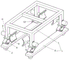
FIG. 1 is a schematic structural diagram of a first embodiment of the present invention;
FIG. 2 is a schematic structural view of the electric putter and its connecting assembly;
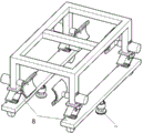
FIG. 3 is a schematic structural diagram of a second embodiment of the present invention;
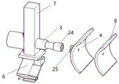
FIG. 4 is a schematic structural view of the telescopic rod and its connecting assembly;
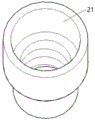
FIG. 5 is a schematic structural view of a rotary drum;
FIG. 6 is a schematic structural diagram of a third embodiment of the present invention;
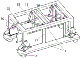
FIG. 7 is a schematic structural diagram of a fourth embodiment of the present invention;
FIG. 8 is a schematic view of the structure of the plunger and its connecting assembly;
the brake comprises a fixing frame 1, a universal brake wheel 2, an electric push rod 3, an arc plate 4, a jack 6, an upper fixing frame 7, a lower fixing frame 8, an anti-slip layer 9, a distance sensor 10, a bulge 11, a telescopic rod 12-P L C, a telescopic rod 13, a cross rod 14, a sliding block 15, a vertical rod 16, an outer tube 17, an inner rod 18, a sliding chute 19, a bearing 20, a rotating cylinder 21, a disc 22, a rubber pad 23, a cylinder 24, a round rod 25, a sliding bearing 26, a vertical plate 27, a rotating rod 28, a concave frame 29, a pull rod 30 and a bolt 31.
Detailed Description
The technical solution in the embodiments of the present invention will be clearly and completely described below with reference to the accompanying drawings in the embodiments of the present invention. It is to be understood that the described embodiments are merely exemplary of the invention, and not restrictive of the full scope of the invention. All other embodiments, which can be derived by a person skilled in the art from the embodiments given herein without making any creative effort, shall fall within the protection scope of the present invention.
Example one
As shown in fig. 1-2, a first embodiment of the present invention is a steel pipe welding device, which includes a fixing frame 1, wherein the fixing frame 1 is composed of an upper fixing frame 7 and a lower fixing frame 8, the lower fixing frame 8 is a first rectangular tube parallel to each other, and universal braking wheels 2 are disposed at four corners of the bottom surface of the fixing frame 1, that is, two ends of the lower end surface of the two rectangular tubes are respectively provided with the universal braking wheels 2. The upper fixing frame 7 is composed of three parallel rectangular tubes II, two rectangular tubes III welded at two ends of the rectangular tubes II and 4 vertical rods 16 vertically welded at the bottom end faces of the rectangular tubes III. Set up the symmetry on mount 1 and set up 4 centre gripping subassemblies, the centre gripping subassembly includes that modes such as electric putter 3 and welding fix the arc 4 at electric putter 3's tip, all beats the through-hole through the puncher on every montant 16, interpolation in the through-hole connects electric putter 3, and electric putter 3 passes through the bolt fastening on montant 16, and four arcs 4 are two liang relative. The fixing frame 1 is provided with a driving device for driving the clamping mechanism to move up and down, the driving device is a jack 6, the jacks 6 are arranged in four, a base of the jack 6 is fixed on the upper end face of the lower fixing frame 8 in a welding mode and the like, the upper fixing frame 7 is arranged on the jack 6, the four jacks 6 are in one-to-one correspondence with the four vertical rods 16, and the bottom faces of the vertical rods 16 are vertically fixed at the centers of the top plates of the jacks 6 in a welding mode and the like. The electric push rod 3 extends, the steel pipe is clamped between the arc-shaped plates 4, the jack 6 is lifted, and the steel pipe moves upwards to leave the ground.
In order to increase the friction force between the arc-shaped plate 4 and the steel pipe and prevent the steel pipe from sliding off, the rubber anti-slip layer 9 is fixed on the inner concave surface of the arc-shaped plate 4 through glue, the distance sensor is arranged on the arc-shaped plate 4, as shown in fig. 2, a through hole is punched on the anti-slip layer 9 through a punching machine, a blind hole corresponding to the through hole is punched on the arc-shaped plate 4, the distance sensor 10 is fixed in the blind hole through glue and the like, preferably a laser displacement sensor, a groove (not shown in the figure) for wiring a wire connected with the distance sensor 10 is machined on the arc-shaped plate 4 through a lathe and the like, the wire does not protrude out of the groove, the fixing frame 1 is provided with a P L C12, in the embodiment, the P L C12 is arranged on the upper fixing frame 7, the output end of the first distance sensor is electrically connected with the input end of the P L C12 through the wire.
The method comprises the steps of horizontally placing a steel pipe on the ground, pushing a fixing frame 1 when the steel pipe is used, placing arc-shaped plates 4 on two sides of the steel pipe respectively, enabling the distance between the peripheral surface of an outer ring of the steel pipe and the arc-shaped plates 4 on two sides to be equal, locking a universal brake wheel 2, fixing a lower fixing frame 8, measuring the distance between the top surface of the steel pipe and the ground, the distance between the top surface of the arc-shaped plate and the ground, the diameter of the steel pipe and the distance between the top surface of the arc-shaped plate and the bottom end of the arc-shaped plate by using a ruler, calculating the distance difference between a shaft core of the steel pipe and a shaft core of the arc-shaped plate, inputting the distance difference into a P L C12, starting a jack 6, synchronously extending or shortening the jack 6 under the control of a P L C12 to enable the height of the shaft core of the steel pipe to be equal to the height of the shaft core of the arc-shaped plates 4, starting the electric push rod 3, synchronously extending the anti-slip layer 9 to the steel pipe when the distance between the distance sensor 10 and the surface of the steel pipe is 3.5cm, enabling the anti-slip layer 9 to be in contact with the steel pipe, enabling the steel pipe to be compressed to be tightly pressed on the outer wall of the steel pipe, enabling a huge friction force of the steel pipe to be generated by a worker to be capable of pushing the steel pipe to be capable of pushing.
Example two
As shown in fig. 3-5, a third embodiment of the present invention is shown, and the present embodiment is different from the first embodiment in that a telescopic rod 13 is disposed on a fixing frame 1, the telescopic rod 13 has a structure shown in fig. 3, and includes an outer tube 17 and an inner rod 18 inserted into the outer tube 17, one end of the telescopic rod 13 is disposed on the fixing frame 1, that is, the top end of the outer rod 17 is welded on the bottom surface of the lower fixing frame 8, and the other end is opposite to the ground, that is, the bottom end of the inner rod 18 is opposite to the ground, as shown in fig. 4, two protrusions 11 are welded on two sides of the top end of the inner rod 17, a sliding slot 19 matching with the protrusion 17 is cut on the outer tube 17 by a cutting machine, the inner rod 18 can slide up and down along the sliding slot 19, a position limiting component for limiting the length of the telescopic rod 13 is disposed on, the rotary drum 21 is formed by mode amalgamation such as a section of thick bamboo, linkage segment and lower section of thick bamboo circle through the viscose, and the inner wall of a section of thick bamboo passes through the viscose to be fixed on bearing 20's outer ring is global on the rotary drum 21, and the lower section of thick bamboo of rotary drum 21 passes through lathe processing and goes out the internal thread, goes up through screw die processing on the outer peripheral face of interior pole 18 and goes out with internal thread assorted external screw thread, and interior pole 18 bottom welded fastening disc 22 passes through viscose fixed anti-skidding rubber pad 23 on the disc. When a steel pipe needs to be clamped, the rotary drum 21 is screwed, the bottom end of the inner rod 18 moves downwards, the bottom surface of the rubber pad 23 is tightly attached to the ground, and the fixing frame 1 is fixed.
EXAMPLE III
As shown in fig. 6, a third embodiment of the present invention is different from the first embodiment in that an arc-shaped plate 4 is detachably connected to an end of an electric push rod 3, a cylinder 24 with an opening at one end is welded to the end of the electric push rod 3, an internal thread is machined in the cylinder 24 through a lathe, a round rod 25 is welded to the center of the outer circumferential surface of the arc-shaped plate 4, an external thread matched with the internal thread is machined on the outer circumferential surface of the round rod 25 through a die, and the detachable connection between the arc-shaped plate 4 and the electric push rod 3 is realized through the matching of the internal thread and the external thread.
Example four
As shown in fig. 7-8, a fourth embodiment of the present invention is shown, and the present embodiment is different from the first embodiment in that two cross bars 14 are welded on the top end of an upper fixing frame 7, two sliding blocks 15 are slidably connected on each cross bar 14, each sliding block 15 is a rectangular block structure with a circular hole machined by a lathe, a sliding bearing 26 is fixed in the circular hole through an adhesive, the sliding bearing 26 is sleeved on the cross bar 14, at this time, the sliding block 15 can freely slide on the cross bar 14, a vertical plate 27 is vertically fixed on the lower end surface of the sliding block 15 through an adhesive or the like, a driving component for driving the sliding block 15 to move relatively or oppositely is arranged on the fixing frame 1, the driving component includes a rotating rod 28, the rotating rod 28 is rotatably connected on the sliding block 15, a concave frame 29 is fixed on the left side surface of the sliding block 15 through an adhesive, the rotating rod 28 is, preventing the round shaft from coming off the concave shelf 29. Through holes are punched in the rectangular tubes of the two upper fixing frames 7 on the left side and the cross rods 14 on the left side through a punching machine, pull rods 30 are inserted into the through holes, round holes are respectively punched at the other ends of the two rotary rods 28 on the left side through the punching machine, round shafts are inserted into the round holes, the other ends of the two rotary rods 28 on the left side are hinged by the round shafts, first accommodating holes are cut in the insertion rods 30 through a cutting machine, the hinged parts of the two rotary rods 28 on the left side are placed in the first accommodating holes, round holes matched with the round shafts are punched on the upper top surface and the lower top surface of the first accommodating holes through the punching machine, second baffle plates are welded after the top ends and the bottom ends of the round shafts penetrate through the round holes, the round shafts are prevented from being separated from the insertion rods 30, the connection modes of the two rotary rods 28 on the right side and the insertion rods 30 are, the middle point of the connecting line between the two vertical plates 27 and the middle point of the connecting line between the two opposite arc-shaped plates 4 are positioned on the same vertical plane, before the heights of the arc-shaped plates 4 are adjusted, the rods 30 are pulled outwards, the positions of the fixing frames 1 are adjusted, the four vertical plates 27 are made to be tightly attached to the steel pipes, and then the universal brake wheel 2 is locked. Go up the mount 7 and go up and beat out the screw through the tapping machine, screw thread connection bolt 31, bolt 31 bottom and pull rod 30 upper surface contact screw up bolt 31, produce huge static friction power between bolt 31 and the pull rod 30 upper surface, fix pull rod 30, mount 1 and steel pipe relatively fixed further increase the stability of mount 1.
Finally, the above embodiments are only used for illustrating the technical solutions of the present invention and not for limiting, and other modifications or equivalent substitutions made by the technical solutions of the present invention by those of ordinary skill in the art should be covered within the scope of the claims of the present invention as long as they do not depart from the spirit and scope of the technical solutions of the present invention.
Claims (7)
1. The utility model provides a steel-pipe tower is mobile device for steel pipe welding, its characterized in that, includes mount (1), mount (1) bottom sets up universal brake wheel (2), the symmetry sets up a plurality of centre gripping subassemblies on mount (1), the centre gripping subassembly includes electric putter (3) and sets up arc (4) at electric putter (3) tip, centre gripping steel pipe between arc (4), set up the drive arrangement of drive centre gripping subassembly up-and-down motion on mount (1).
2. The moving device for welding the steel tube of the steel tube tower according to claim 1, wherein the fixed frame (1) is composed of an upper fixed frame (7) and a lower fixed frame (8), the driving device is a jack (6), the jack (6) is arranged on the lower fixed frame (8), the upper fixed frame (7) is arranged on the jack (6), the electric push rod (3) is arranged on the upper fixed frame (7), and the universal brake wheels (2) are arranged at four corners of the bottom surface of the lower fixed frame (8).
3. The moving device for welding the steel tube of the steel tube tower according to claim 1, wherein an anti-slip layer (9) is fixed on the inner concave surface of the arc-shaped plate (4) through glue.
4. The moving device for welding the steel tube of the steel tube tower according to claim 2, wherein a distance sensor (10) is arranged on the arc-shaped plate (4), a P L C (12) is arranged on the fixed frame, the distance sensor (10) is electrically connected with an input end of the P L C (12), and the P L C (12) is electrically connected with a control end of the electric push rod (3) and the jack (6).
5. The moving device for welding the steel tube tower and the steel tube according to claim 1, wherein a telescopic rod (13) is arranged at the bottom end of the fixed frame (1), one end of the telescopic rod (13) is arranged on the fixed frame (1), and the other end of the telescopic rod is opposite to the ground.
6. The moving device for welding the steel tube of the steel tube tower according to claim 1, wherein the arc-shaped plate (4) is detachably connected with the end part of the electric push rod (3).
7. The moving device for welding the steel tube of the steel tube tower according to claim 2, wherein two or more cross rods (14) are arranged at the top end of the upper fixing frame (7), each cross rod (14) is connected with two sliding blocks (15) in a sliding mode, a vertical rod (27) is arranged below each sliding block (15), and a driving assembly for driving the sliding blocks (15) to move relatively or oppositely is arranged on the fixing frame (1).
Priority Applications (1)
| Application Number | Priority Date | Filing Date | Title |
|---|---|---|---|
| CN202010357918.7A CN111483942B (en) | 2020-04-29 | 2020-04-29 | Moving device for welding steel pipes of steel pipe tower |
Applications Claiming Priority (1)
| Application Number | Priority Date | Filing Date | Title |
|---|---|---|---|
| CN202010357918.7A CN111483942B (en) | 2020-04-29 | 2020-04-29 | Moving device for welding steel pipes of steel pipe tower |
Publications (2)
| Publication Number | Publication Date |
|---|---|
| CN111483942A true CN111483942A (en) | 2020-08-04 |
| CN111483942B CN111483942B (en) | 2021-10-22 |
Family
ID=71813201
Family Applications (1)
| Application Number | Title | Priority Date | Filing Date |
|---|---|---|---|
| CN202010357918.7A Active CN111483942B (en) | 2020-04-29 | 2020-04-29 | Moving device for welding steel pipes of steel pipe tower |
Country Status (1)
| Country | Link |
|---|---|
| CN (1) | CN111483942B (en) |
Cited By (5)
| Publication number | Priority date | Publication date | Assignee | Title |
|---|---|---|---|---|
| CN112125220A (en) * | 2020-08-31 | 2020-12-25 | 常州工学院 | Aerospace shell mounting device |
| CN112518383A (en) * | 2020-12-14 | 2021-03-19 | 宁波阅荷思山智能科技有限公司 | Clamping device and clamping method of high-precision numerical control machine tool |
| CN112693514A (en) * | 2021-03-18 | 2021-04-23 | 新乡职业技术学院 | Hoisting device for mechanical equipment maintenance |
| CN113233007A (en) * | 2021-05-18 | 2021-08-10 | 中车四方车辆有限公司 | Support device for storing railway carriage bogie |
| CN117444605A (en) * | 2023-12-22 | 2024-01-26 | 江苏常友环保科技股份有限公司 | Cabin cover assembly adjusting device |
Citations (5)
| Publication number | Priority date | Publication date | Assignee | Title |
|---|---|---|---|---|
| CN104691593A (en) * | 2013-12-06 | 2015-06-10 | 大连愚人设计有限公司 | Circular tube transporting system |
| CN204828935U (en) * | 2015-08-23 | 2015-12-02 | 翟一卜 | Petroleum pipeline special fixture |
| KR20190114240A (en) * | 2018-03-29 | 2019-10-10 | 인하대학교 산학협력단 | Steel pile head fixing and cutting apparatus |
| CN209762441U (en) * | 2019-04-30 | 2019-12-10 | 中国通信建设集团设计院有限公司 | Communication base station angle steel tower ventilation pipe fastener |
| CN110711096A (en) * | 2019-11-26 | 2020-01-21 | 燕山大学 | Foldable transfer nursing robot |
-
2020
- 2020-04-29 CN CN202010357918.7A patent/CN111483942B/en active Active
Patent Citations (5)
| Publication number | Priority date | Publication date | Assignee | Title |
|---|---|---|---|---|
| CN104691593A (en) * | 2013-12-06 | 2015-06-10 | 大连愚人设计有限公司 | Circular tube transporting system |
| CN204828935U (en) * | 2015-08-23 | 2015-12-02 | 翟一卜 | Petroleum pipeline special fixture |
| KR20190114240A (en) * | 2018-03-29 | 2019-10-10 | 인하대학교 산학협력단 | Steel pile head fixing and cutting apparatus |
| CN209762441U (en) * | 2019-04-30 | 2019-12-10 | 中国通信建设集团设计院有限公司 | Communication base station angle steel tower ventilation pipe fastener |
| CN110711096A (en) * | 2019-11-26 | 2020-01-21 | 燕山大学 | Foldable transfer nursing robot |
Cited By (8)
| Publication number | Priority date | Publication date | Assignee | Title |
|---|---|---|---|---|
| CN112125220A (en) * | 2020-08-31 | 2020-12-25 | 常州工学院 | Aerospace shell mounting device |
| CN112518383A (en) * | 2020-12-14 | 2021-03-19 | 宁波阅荷思山智能科技有限公司 | Clamping device and clamping method of high-precision numerical control machine tool |
| CN112518383B (en) * | 2020-12-14 | 2022-01-14 | 广东兆丰泰机电科技有限公司 | Clamping device and clamping method of high-precision numerical control machine tool |
| CN112693514A (en) * | 2021-03-18 | 2021-04-23 | 新乡职业技术学院 | Hoisting device for mechanical equipment maintenance |
| CN112693514B (en) * | 2021-03-18 | 2021-06-18 | 新乡职业技术学院 | Hoisting device for mechanical equipment maintenance |
| CN113233007A (en) * | 2021-05-18 | 2021-08-10 | 中车四方车辆有限公司 | Support device for storing railway carriage bogie |
| CN117444605A (en) * | 2023-12-22 | 2024-01-26 | 江苏常友环保科技股份有限公司 | Cabin cover assembly adjusting device |
| CN117444605B (en) * | 2023-12-22 | 2024-03-08 | 江苏常友环保科技股份有限公司 | Cabin cover assembly adjusting device |
Also Published As
| Publication number | Publication date |
|---|---|
| CN111483942B (en) | 2021-10-22 |
Similar Documents
| Publication | Publication Date | Title |
|---|---|---|
| CN111483942A (en) | Moving device for welding steel pipes of steel pipe tower | |
| CN219825244U (en) | Pile driver for bridge construction | |
| CN211166982U (en) | Support arrangement suitable for assembly type structure | |
| CN215569398U (en) | Energy-saving dynamic compaction construction automatic monitoring device | |
| CN216127264U (en) | Scraper bowl assembly welding robot | |
| CN220972320U (en) | General type stand of high accuracy equipment | |
| CN214653452U (en) | Pipeline welding elevating platform | |
| CN218116448U (en) | Engineering pile pulling equipment convenient to use | |
| CN219511829U (en) | Sampling device | |
| CN213576260U (en) | Hoisting accessory mount for ocean detector | |
| CN219038426U (en) | Hydrogeology sampling device | |
| CN213541079U (en) | Movable lifting platform up-down guiding device | |
| CN221396997U (en) | Hoisting equipment for shield tunneling machine assembly | |
| CN221572150U (en) | Stone curtain wall corner strength detection equipment | |
| CN113959408B (en) | Transmission line shaft tower slope detection device | |
| CN214780344U (en) | Electric block installation device | |
| CN213410764U (en) | Moving device of projection welding machine | |
| CN214411728U (en) | Device is installed and removed to transformer substation's earth connection | |
| CN215901795U (en) | Butterfly clamp titration table | |
| CN220751619U (en) | Carriage detection support for new energy automobile | |
| CN217703047U (en) | Fixing device for mechanical equipment maintenance | |
| CN219810655U (en) | Be used for agricultural technology to popularize and sample drilling rig | |
| CN218617318U (en) | Wire rod packing is with packing carousel | |
| CN212954134U (en) | Chassis detection lifting device for automobile manufacturing | |
| CN211920394U (en) | Cable shaft paying-off equipment |
Legal Events
| Date | Code | Title | Description |
|---|---|---|---|
| PB01 | Publication | ||
| PB01 | Publication | ||
| SE01 | Entry into force of request for substantive examination | ||
| SE01 | Entry into force of request for substantive examination | ||
| GR01 | Patent grant | ||
| GR01 | Patent grant |