CN111482214A - Special test tube clamping device of blood test - Google Patents
Special test tube clamping device of blood test Download PDFInfo
- Publication number
- CN111482214A CN111482214A CN202010252560.1A CN202010252560A CN111482214A CN 111482214 A CN111482214 A CN 111482214A CN 202010252560 A CN202010252560 A CN 202010252560A CN 111482214 A CN111482214 A CN 111482214A
- Authority
- CN
- China
- Prior art keywords
- fixedly connected
- test tube
- clamping
- rod
- rods
- Prior art date
- Legal status (The legal status is an assumption and is not a legal conclusion. Google has not performed a legal analysis and makes no representation as to the accuracy of the status listed.)
- Withdrawn
Links
Images


Classifications
-
- B—PERFORMING OPERATIONS; TRANSPORTING
- B01—PHYSICAL OR CHEMICAL PROCESSES OR APPARATUS IN GENERAL
- B01L—CHEMICAL OR PHYSICAL LABORATORY APPARATUS FOR GENERAL USE
- B01L9/00—Supporting devices; Holding devices
- B01L9/06—Test-tube stands; Test-tube holders
Abstract
The invention relates to the technical field of testing tools, in particular to a special test tube clamping device for blood testing, which comprises a handle, a bottom plate, a sliding rod, a supporting cylinder, a pressure rod, an upper clamping plate, a lower clamping plate, a distance adjusting device, a clamping rod, a clamping arm and a push-pull rod, wherein the handle is of a cylindrical structure with an opening at the upper end, the upper end of the handle is fixedly connected with the bottom plate vertical to the handle, two supporting cylinders vertical to the bottom plate are symmetrically and fixedly connected to two ends of the top surface of the bottom plate, and the sliding rod is inserted in the supporting. The test tube clamp has the advantages that the structural design is reasonable, the upper clamp plate and the lower clamp plate or the clamp arms can be opened to clamp the test tube by pressing the pressing plate downwards, the test tube can be clamped under the elastic action of the reset spring and the compression spring after the pressing plate is loosened, the clamp can be locked and fixed through the limiting nut, the test tube can be clamped without continuously exerting force, the test tube can be prevented from slipping, one test tube can be clamped through the clamp arms, a plurality of test tubes can be simultaneously clamped through a plurality of groups of upper clamp plates and lower clamp plates for taking, cleaning and disinfecting, the time and labor are.
Description
Technical Field
The invention relates to the technical field of testing tools, in particular to a special test tube clamping device for blood testing.
Background
The blood test refers to a test for determining the conditions of anemia, cholesterol, diabetes, various infections, renal function, calcium, liver function, blood diseases, body abnormalities, and the like of a human body by blood analysis and examination. It is one of the most common test contents in hospitals. Blood tests are prescribed by orders and physicians use the test results to clarify or support diagnosis, supervise or determine treatment and screen for undetermined disease conditions. A large amount of test tubes are used in blood inspection, when the test tubes are cleaned and disinfected in the using process and after being used, the test tube clamping devices are usually used for clamping the fixed test tubes, the existing test tube clamping devices are generally clamping pincers, but the clamping pincers are used, an operator is required to apply certain force to the clamping pincers all the time, the clamping is pressed, the test tubes can be clamped once by the existing clamping pincers, attention is dispersed easily, the clamping of hands in the test tube clamping process can reduce the pressurizing degree, the clamping is not tight, the test tubes can fall off, the detection of blood samples is influenced, in addition, the existing clamping pincers can only clamp one test tube once, when the test tubes are cleaned and disinfected and taken from the test tube rack, only one test tube can be clamped for use, time and labor are wasted, the efficiency is low, and great inconvenience is realized.
To sum up, this technical scheme need continuously exert oneself and can not lock and can only single test tube carry out the technical problem that the clamping efficiency is low when solving current centre gripping pincers centre gripping, provides a special test tube clamping device of blood test.
Disclosure of Invention
The invention aims to overcome the technical defects and provide a special test tube clamping device for blood test. The clamp plate of pushing down can make punch holder or arm lock open and carry out the centre gripping to the test tube, can press from both sides tight test tube under reset spring and compression spring's elastic action after loosening the clamp plate, and can lock the fastening through stop nut to the centre gripping and fix, need not to continuously can press from both sides tight test tube hard, can avoid the test tube slippage, can use test tube of arm lock centre gripping, also can take and wash the disinfection through a plurality of test tubes of multiunit punch holder centre gripping simultaneously, and is time-saving and labor-saving, and it is very convenient to use.
The technical scheme adopted by the invention for solving the technical problems is as follows: a special test tube clamping device for blood test comprises a handle, a bottom plate, sliding rods, supporting cylinders, a pressure rod, an upper clamping plate, a lower clamping plate, a distance adjusting device, a clamping rod, a clamping arm and a push-pull rod, wherein the handle is of a cylindrical structure with an open upper end, the upper end of the handle is fixedly connected with the bottom plate which is perpendicular to the handle, a guide hole is fixedly arranged at the center of the bottom plate, the guide hole is communicated with a cylinder cavity of the handle, a compression rod is inserted in the guide hole in a sliding manner, two supporting cylinders which are perpendicular to the top surface of the bottom plate are symmetrically and fixedly connected with the two ends of the top surface of the bottom plate, the sliding rods are inserted in the supporting cylinders in a sliding manner, sliding grooves are respectively arranged on the outer walls of the opposite sides of the two supporting cylinders, a plurality of thread distance adjusting grooves are uniformly arranged on the outer walls of the inner sides of the sliding rods, a section of external, the two ends of the pressure rod penetrate through the sliding grooves on the two sides and then the lower ends of the two sliding rods are fixedly connected, the center of the outer wall of the upper side of the pressure rod is fixedly connected with a push-pull ring, the outer wall of the upper end of the compression rod is provided with external threads, an adjusting nut is fixed on the outer wall of the upper end of the compression rod in a screwed mode, a reset spring is sleeved on the compression rod between the adjusting nut and the handle, the upper clamp plate and the lower clamp plate are in a group and are arc-shaped clamp plates which are oppositely arranged, the upper clamp plate and the lower clamp plate are provided with a plurality of groups, the two ends of the lower clamp plate are both provided with fixed thread grooves, connecting screw rods are fixed in the fixed thread grooves in a screwed mode, the other ends of the connecting screw rods penetrate through the sliding grooves and then are fixed in thread distance-adjusting grooves, the outer wall of the middle, the outer wall of the other side of the sliding sleeve is fixedly connected with a fixed rod, the upper ends of two adjacent fixed rods are fixedly connected with a distance adjusting device, the distance adjusting device consists of a distance adjusting threaded cylinder and two distance adjusting threaded rods, two ends of the distance adjusting threaded cylinder are fixedly connected with the two distance adjusting threaded rods in a screwed mode, the screw directions of the two distance adjusting threaded rods are opposite, the other ends of the two distance adjusting threaded rods are fixedly connected to the upper ends of the fixed rods, locking bolts are fixedly connected to the sliding sleeves at the uppermost ends of the two sides in a screwed mode, a clamping rod with a square cross section is fixedly connected between the upper ends of the two supporting cylinders, the clamping rod is symmetrically and slidably sleeved with the two adjusting sleeves, two arc-shaped clamping arms which are oppositely arranged are symmetrically and fixedly connected to the outer wall of the upper side of the two adjusting sleeves, limiting pieces are fixedly connected to the outer walls of the two ends of the clamping rod, a compression, the threaded distance-adjusting groove at the uppermost end of the sliding rod is internally and fixedly connected with a hinged rod in a threaded manner, the push-pull rod is provided with two hinged frames, the two ends of each hinged frame are fixedly connected with U-shaped hinges, and the hinged frames at the two ends are respectively hinged and fixed on the hinged rod and the hinged sheet through hinged shafts.
Preferably, the lower end of the handle is fixed with a rubber suction cup in a threaded manner.
Preferably, the outer wall of the handle is fixedly sleeved with a high-density sponge sleeve.
Preferably, a plurality of semi-spherical silica gel bulges are uniformly fixed on the inner wall of the push-pull ring.
Preferably, the inner side outer walls of the upper clamping plate, the lower clamping plate and the clamping arms are fixedly connected with a layer of rubber pad.
Preferably, the upper and lower clamping plates are provided with 6 sets.
The invention has the beneficial effects that: the test tube clamp has the advantages that the structural design is reasonable, the upper clamp plate and the lower clamp plate or the clamp arms can be opened to clamp the test tube by pressing the pressing plate downwards, the test tube can be clamped under the elastic action of the reset spring and the compression spring after the pressing plate is loosened, the clamp can be locked and fixed through the limiting nut, the test tube can be clamped without continuously exerting force, the test tube can be prevented from slipping, one test tube can be clamped through the clamp arms, a plurality of test tubes can be simultaneously clamped through a plurality of groups of upper clamp plates and lower clamp plates for taking, cleaning and disinfecting, the time and labor are saved.
Drawings
In order to more clearly illustrate the technical solutions of the embodiments of the present invention, the drawings used in the description of the embodiments will be briefly introduced below, and it is obvious that the drawings in the following description are only some embodiments of the present invention, and it is obvious for those skilled in the art that other drawings can be obtained according to the drawings without creative efforts.
FIG. 1 is a schematic structural diagram of the present invention.
FIG. 2 is a schematic view of the connection structure of the handle and the bottom plate of the present invention.
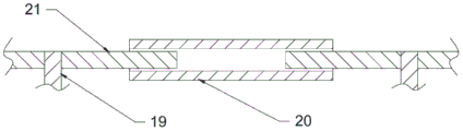
Fig. 3 is a schematic view of a connection structure of the distance adjusting device and the fixing rod of the present invention.
Fig. 4 is a schematic view of a connection structure of the lower plate and the slide bar according to the present invention.
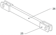
Fig. 5 is a schematic view of a connection structure of the push-pull rod and the hinge frame according to the present invention.
Fig. 6 is a schematic view of a connection structure of the slide bar and the press bar according to the present invention.
Detailed Description
The technical solutions in the embodiments of the present invention will be clearly and completely described below with reference to the drawings in the embodiments of the present invention, and it is obvious that the described embodiments are only a part of the embodiments of the present invention, and not all of the embodiments. All other embodiments, which can be derived by a person skilled in the art from the embodiments given herein without making any creative effort, shall fall within the protection scope of the present invention.
In the description of the present invention, it is to be understood that the terms "upper", "middle", "lower", "outer", "inner", and the like, indicate orientations or positional relationships, are used for convenience in describing the present invention and simplifying the description, but do not indicate or imply that the referenced components or elements must have a particular orientation, be constructed and operated in a particular orientation, and thus, should not be construed as limiting the present invention.
The present invention will be described in detail below with reference to fig. 1 to 6.
As shown in fig. 1 to 6, the invention comprises a handle 1, a bottom plate 4, a sliding rod 6, supporting cylinders 5, a pressure rod 3, an upper clamping plate 16, a lower clamping plate 15, a distance adjusting device, a clamping rod 29, a clamping arm 31 and a push-pull rod 26, wherein the handle 1 is a cylindrical structure with an open upper end, the upper end of the handle is fixedly connected with the bottom plate 4 vertical to the handle, a guide hole 33 is fixedly arranged at the center of the bottom plate 4, the guide hole 33 is communicated with a cylinder cavity of the handle 1 and is internally inserted with a compression rod 10 in a sliding manner, two supporting cylinders 5 vertical to the bottom plate 4 are symmetrically and fixedly connected with two ends of the top surface of the bottom plate 4, the sliding rod 6 is inserted in the supporting cylinders 5 in a sliding manner, sliding grooves 35 are arranged on the outer walls of the opposite sides of the two supporting cylinders 5, a plurality of threaded distance adjusting grooves 34 are uniformly arranged on the outer walls of the inner sides of the sliding rod 6, and the distance adjusting, conveniently and simultaneously taking and placing a plurality of test tubes, the upper ends of two sliding rods 6 are provided with a section of external thread, the end parts of the two sliding rods extend out of the upper end of a supporting cylinder 5 and then are fixedly connected with a limiting nut 7 in a screwed mode, after the test tubes are clamped, the limiting nut 7 can be rotated to the upper end of the supporting cylinder 5, a lower clamping plate 15 or a clamping arm 31 can be prevented from being movably opened, the clamping degree of the test tubes can be locked in clamping mode, the clamping is firmer, the upper end of a compression rod 10 is fixedly connected to the center of the bottom surface of a compression rod 3, the two ends of the compression rod 3 penetrate through sliding grooves 35 on two sides and then are fixedly connected to the lower ends of the two sliding rods 6, the center of the outer wall of the upper side of the compression rod 3 is fixedly connected with a push-pull ring 11, the outer wall of the upper end of the compression rod 10 is provided, when the test tube is rotated downwards, the clamping force of the test tube can be increased, otherwise, the clamping force is reduced, the reset spring 8 can enable the press rod 3 to move upwards and reset, the lower clamp plate 15 moves upwards to clamp the test tube with the upper clamp plate 16, the upper clamp plate 16 and the lower clamp plate 15 are in a group, the upper clamp plate 16 and the lower clamp plate 15 are in arc shapes and are oppositely arranged, a plurality of groups are arranged on the upper clamp plate 16 and the lower clamp plate 15, both ends of the lower clamp plate 15 are respectively provided with a fixed thread groove 36, a connecting screw 13 is fixedly connected in the fixed thread grooves 36 in a threaded manner, the other end of the connecting screw 13 penetrates through a sliding groove 35 and then is fixedly connected in the thread distance-adjusting groove 34 in a threaded manner, an adjusting knob 14 is fixedly connected on the outer wall of the middle of the connecting screw 13, the connecting screw 13 can be conveniently taken out of the thread distance-adjusting groove 34 by rotating the adjusting knob 14 and then is, the upper clamping plate 16 and the lower clamping plate 15 are clamped firmly, two connecting rods 23 are fixedly connected to two ends of the upper clamping plate 16, sliding sleeves 18 are fixedly connected to the other ends of the connecting rods 23, the two sliding sleeves 18 are respectively sleeved on the supporting cylinders 5 on two sides, fixing rods 19 are fixedly connected to the outer wall of the other side of each sliding sleeve 18, a distance adjusting device is fixedly connected between the upper ends of the two adjacent fixing rods 19 and consists of a distance adjusting threaded cylinder 20 and two distance adjusting threaded rods 21, the two ends of the distance adjusting threaded cylinder 20 are fixedly connected with the two distance adjusting threaded rods 21 in a threaded manner, the two distance adjusting threaded rods 21 are opposite in threaded direction, the other ends of the two distance adjusting threaded rods 21 are fixedly connected to the upper ends of the fixing rods 19, locking bolts 22 are fixedly connected to the sliding sleeves 18 on the uppermost ends of the two sides in a threaded manner, and corresponding adjustment can be carried out on the distance between the, the cross section of the fixedly connected part between the upper ends of the two supporting cylinders 5 is a square clamping rod 29, the clamping rod 29 is symmetrically and slidably sleeved with two adjusting sleeves 28, the outer wall of the upper side of the two adjusting sleeves 28 is symmetrically and fixedly connected with two arc-shaped clamping arms 31 which are oppositely arranged, the outer walls of the two ends of the clamping rod 29 are fixedly connected with limiting pieces 37, the clamping rod 29 between the limiting pieces 37 and the adjusting sleeves 28 is slidably sleeved with a compression spring 30, the outer wall of the lower end of the adjusting sleeves 28 is fixedly connected with semicircular hinged pieces 27, the uppermost end of the sliding rod 6 is fixedly connected with a hinged rod 24 in a threaded distance-adjusting groove 34 in an threaded manner, the push-pull rod 26 is provided with two hinged frames 25, the two ends of each hinged frame 25 are fixedly connected with a U-shaped hinged frame 24, and the hinged frames 25 at the two ends are respectively. The lower pull-down rod 3 can enable the hinge rod 24 to pull two distance adjusting sleeves to be relatively far away, so that the two clamping arms 31 are opened to clamp and fix the test tube, and the two clamping arms 31 can be reset and clamped under the action of the reset spring 8 and the compression spring 30 after being loosened.
Further, a rubber suction cup 32 is fixed to the lower end of the handle 1 in a threaded manner. The rubber suction cup 32 can be adsorbed on the experiment table top, so that the device is vertically and fixedly placed.
Further, a high-density sponge sleeve 2 is fixedly sleeved on the outer wall of the handle 1. The high-density sponge sleeve 2 can absorb sweat and prevent slipping, and is convenient to hold.
Furthermore, a plurality of hemispherical silica gel bulges 12 are uniformly fixed on the inner wall of the pulling ring 11. The silica gel bulge 12 can make the finger insert push-pull ring 11 in when carrying out the push-pull, the travelling comfort is better.
Furthermore, a layer of rubber pad 17 is fixedly connected to the inner outer walls of the upper clamping plate 16, the lower clamping plate 15 and the clamping arms 31. Rubber pad 17 can make the centre gripping of test tube fixed more firm.
Further, the upper clamping plate 16 and the lower clamping plate 15 are provided with 6 groups. Be equipped with 6 groups and can the fixed 6 test tubes of centre gripping simultaneously, convenience simple to use, it is efficient.
When the test tube clamp is used, when a single test tube is clamped, the push-pull ring 11 can be pulled downwards to drive the sliding rod 6 to move downwards, the two clamping arms 31 can be separated in parallel under the pulling of the hinge rod 24 to clamp the test tube, the push-pull ring 11 is loosened, the two clamping arms 31 can reset to clamp the test tube under the action of the reset spring 8 and the compression spring 30, the clamping force can be locked by rotating the adjusting nut 9, and the two clamping arms 31 can clamp the test tube and cannot be opened; when a plurality of test tubes are simultaneously clamped, the spacing between the test tubes on the test tube rack can be according to, the spacing between the upper clamping plates 16 is adjusted through the distance adjusting device, meanwhile, the connecting screw rods 13 at the two ends of the lower clamping plates 15 can be correspondingly screwed in the corresponding thread distance adjusting grooves 34 as required, the spacing between the lower clamping plates 15 and the upper clamping plates 16 and the spacing between the two lower clamping plates 15 are adjusted, the lower pull-push ring 11 is pulled down, the lower clamping plates 15 and the upper clamping plates 16 can be separated, a plurality of test tubes are simultaneously clamped, the pull-push ring 11 is loosened, the test tubes are reset under the action of the reset spring 8 and the compression spring 30, the upper clamping plates 16 and the lower clamping plates 15 are tightly fixed, and the clamping force can be locked by the rotary adjusting nut 9.
It will be evident to those skilled in the art that the invention is not limited to the details of the foregoing illustrative embodiments, and that the present invention may be embodied in other specific forms without departing from the spirit or essential attributes thereof. The present embodiments are, therefore, to be considered in all respects as illustrative and not restrictive.
Furthermore, it should be understood that although the present description refers to embodiments, not every embodiment may contain only a single embodiment, and such description is for clarity only, and those skilled in the art should integrate the description, and the embodiments may be combined as appropriate to form other embodiments understood by those skilled in the art.
Claims (6)
1. The utility model provides a special test tube clamping device of blood test, includes handle, bottom plate, slide bar, a support section of thick bamboo, depression bar, punch holder, lower plate, roll adjustment device, supporting rod, arm lock, push-and-pull rod, its characterized in that: the handle is of a cylindrical structure with an opening at the upper end, the upper end of the handle is fixedly connected with a bottom plate perpendicular to the handle, a guide hole is fixedly arranged at the center of the bottom plate, the guide hole is communicated with a cylinder cavity of the handle and is internally inserted with a compression rod in a sliding manner, two supporting cylinders perpendicular to the bottom plate are symmetrically and fixedly connected with two ends of the top surface of the bottom plate, sliding rods are inserted in the supporting cylinders in a sliding manner, sliding grooves are respectively arranged on the outer walls of the two opposite sides of the two supporting cylinders, a plurality of thread distance-adjusting grooves are uniformly arranged on the outer walls of the inner sides of the sliding rods, the upper ends of the two sliding rods are respectively provided with a section of external thread, the end parts of the two sliding rods extend out of the upper ends of the supporting cylinders and are fixedly connected with a limiting nut, the upper ends of the compression rods are fixedly connected with the center of the bottom surface of the compression rod after passing through the sliding grooves, a reset spring is sleeved on a compression rod between the adjusting nut and the handle, the upper clamping plate and the lower clamping plate are a group of arc-shaped clamping plates which are oppositely arranged, the upper clamping plate and the lower clamping plate are provided with a plurality of groups, both ends of the lower clamping plate are provided with fixed thread grooves, connecting screw rods are fixedly connected in the fixed thread grooves in a screwed manner, the other ends of the connecting screw rods pass through the sliding grooves and then are fixedly connected in threaded distance-adjusting grooves in a screwed manner, an adjusting knob is fixedly connected on the outer wall of the middle part of each connecting screw rod, both ends of the upper clamping plate are fixedly connected with two connecting rods, the other ends of the connecting rods are fixedly connected with sliding sleeves, the two sliding sleeves are respectively sleeved on supporting cylinders at both sides, fixing rods are fixedly connected on the outer wall of the other side of each sliding sleeve, a distance-adjusting device is fixedly connected between the upper, two ends of the distance-adjusting threaded barrel are fixedly connected with two distance-adjusting threaded rods in a screwed manner, the screw directions of the two distance-adjusting threaded rods are opposite, the other ends of the two distance-adjusting threaded rods are fixedly connected to the upper end of the fixed rod, locking bolts are fixedly connected to the sliding sleeves at the uppermost ends of the two sides in a screwed manner, a clamping rod with a square cross section is fixedly connected between the upper ends of the two supporting barrels, two adjusting sleeves are symmetrically and slidably sleeved on the clamping rod, two arc-shaped clamping arms which are oppositely arranged are symmetrically and fixedly connected to the outer walls of the upper sides of the two adjusting sleeves, limiting plates are fixedly connected to the outer walls of the two ends of the clamping rod, a compression spring is slidably sleeved on the clamping rod between the limiting plate and the adjusting sleeve, semicircular hinge plates are fixedly connected to the outer wall of the lower end of the adjusting sleeve, hinge rods are fixedly connected to the threaded distance-adjusting, the hinged frames at the two ends are respectively hinged and fixed on the hinged rod and the hinged sheet through the hinged shaft.
2. The special test tube holding device for blood test according to claim 1, wherein: the lower end of the handle is fixed with a rubber sucker in a threaded manner.
3. The special test tube holding device for blood test according to claim 1, wherein: the outer wall of the handle is fixedly sleeved with a high-density sponge sleeve.
4. The special test tube holding device for blood test according to claim 1, wherein: a plurality of hemispherical silica gel bulges are uniformly fixed on the inner wall of the push-pull ring.
5. The special test tube holding device for blood test according to claim 1, wherein: and the inner side outer walls of the upper clamping plate, the lower clamping plate and the clamping arms are fixedly connected with a layer of rubber pad.
6. The special test tube holding device for blood test according to claim 1, wherein: the upper splint and the lower splint are provided with 6 groups.
Priority Applications (1)
| Application Number | Priority Date | Filing Date | Title |
|---|---|---|---|
| CN202010252560.1A CN111482214A (en) | 2020-04-01 | 2020-04-01 | Special test tube clamping device of blood test |
Applications Claiming Priority (1)
| Application Number | Priority Date | Filing Date | Title |
|---|---|---|---|
| CN202010252560.1A CN111482214A (en) | 2020-04-01 | 2020-04-01 | Special test tube clamping device of blood test |
Publications (1)
| Publication Number | Publication Date |
|---|---|
| CN111482214A true CN111482214A (en) | 2020-08-04 |
Family
ID=71797665
Family Applications (1)
| Application Number | Title | Priority Date | Filing Date |
|---|---|---|---|
| CN202010252560.1A Withdrawn CN111482214A (en) | 2020-04-01 | 2020-04-01 | Special test tube clamping device of blood test |
Country Status (1)
| Country | Link |
|---|---|
| CN (1) | CN111482214A (en) |
Cited By (3)
| Publication number | Priority date | Publication date | Assignee | Title |
|---|---|---|---|---|
| CN111992269A (en) * | 2020-09-25 | 2020-11-27 | 山东交通职业学院 | Road transportation analogue test platform |
| CN112485066A (en) * | 2020-12-27 | 2021-03-12 | 刘秀英 | Medical science inspection liquid multitube difference sampling device |
| CN115090174A (en) * | 2022-05-13 | 2022-09-23 | 国网内蒙古东部电力有限公司通辽供电公司 | Oscillating mixer |
Citations (17)
| Publication number | Priority date | Publication date | Assignee | Title |
|---|---|---|---|---|
| US20030161764A1 (en) * | 2002-02-28 | 2003-08-28 | Teruaki Itoh | Test tube holder |
| EP2231335A1 (en) * | 2007-10-17 | 2010-09-29 | Rainin Instrument LLC. | Liquid end assembly for a handheld multichannel pipette with adjustable nozzle spacing |
| US20160075462A1 (en) * | 2013-04-15 | 2016-03-17 | Energium., Ltd | Test tube gripper, test tube labeling unit, and test tube preparing apparatus including the same |
| CN108176422A (en) * | 2017-12-08 | 2018-06-19 | 张荷友 | A kind of chemical laboratory experimental stirring beaker base |
| CN108201904A (en) * | 2018-01-03 | 2018-06-26 | 佛山杰致信息科技有限公司 | A kind of analytical chemistry classroom instruction laboratory vehicle |
| CN108479890A (en) * | 2018-06-11 | 2018-09-04 | 杨玲玲 | A kind of foldable test tube rack that stability is good |
| CN207941560U (en) * | 2017-12-28 | 2018-10-09 | 南京卡文思检测技术有限公司 | A kind of test tube for laboratory room |
| CN208177488U (en) * | 2018-03-14 | 2018-12-04 | 福建省德鲁士润滑油有限公司 | A kind of adjustable medical test tube clamp |
| CN109046510A (en) * | 2018-10-15 | 2018-12-21 | 黄超 | A kind of chemical laboratory rack for test tube |
| CN208407953U (en) * | 2018-04-08 | 2019-01-22 | 殷毡毡 | A kind of chemical industry test tube cleaning device |
| CN208407064U (en) * | 2018-05-11 | 2019-01-22 | 郭浩帆 | A kind of teaching Bioexperiment platform |
| CN109569763A (en) * | 2018-12-17 | 2019-04-05 | 张云生 | A kind of modified rack for test tube and its installation method |
| CN109622103A (en) * | 2019-02-15 | 2019-04-16 | 于媛媛 | A kind of clinical laboratory's test tube clamp that stability is high |
| CN208839631U (en) * | 2018-07-12 | 2019-05-10 | 绍兴市寅源智能科技有限公司 | A kind of chemistry teaching test tube clamping device |
| CN209438658U (en) * | 2018-07-20 | 2019-09-27 | 南京市第一医院 | One kind is portable to take urine test tube clamp |
| US20190383431A1 (en) * | 2018-06-13 | 2019-12-19 | TKO Clamping Systems, LLC | Clamping devices, systems and methods |
| CN209901330U (en) * | 2019-01-08 | 2020-01-07 | 唐兵 | Experiment operation table for electronic technology development |
-
2020
- 2020-04-01 CN CN202010252560.1A patent/CN111482214A/en not_active Withdrawn
Patent Citations (17)
| Publication number | Priority date | Publication date | Assignee | Title |
|---|---|---|---|---|
| US20030161764A1 (en) * | 2002-02-28 | 2003-08-28 | Teruaki Itoh | Test tube holder |
| EP2231335A1 (en) * | 2007-10-17 | 2010-09-29 | Rainin Instrument LLC. | Liquid end assembly for a handheld multichannel pipette with adjustable nozzle spacing |
| US20160075462A1 (en) * | 2013-04-15 | 2016-03-17 | Energium., Ltd | Test tube gripper, test tube labeling unit, and test tube preparing apparatus including the same |
| CN108176422A (en) * | 2017-12-08 | 2018-06-19 | 张荷友 | A kind of chemical laboratory experimental stirring beaker base |
| CN207941560U (en) * | 2017-12-28 | 2018-10-09 | 南京卡文思检测技术有限公司 | A kind of test tube for laboratory room |
| CN108201904A (en) * | 2018-01-03 | 2018-06-26 | 佛山杰致信息科技有限公司 | A kind of analytical chemistry classroom instruction laboratory vehicle |
| CN208177488U (en) * | 2018-03-14 | 2018-12-04 | 福建省德鲁士润滑油有限公司 | A kind of adjustable medical test tube clamp |
| CN208407953U (en) * | 2018-04-08 | 2019-01-22 | 殷毡毡 | A kind of chemical industry test tube cleaning device |
| CN208407064U (en) * | 2018-05-11 | 2019-01-22 | 郭浩帆 | A kind of teaching Bioexperiment platform |
| CN108479890A (en) * | 2018-06-11 | 2018-09-04 | 杨玲玲 | A kind of foldable test tube rack that stability is good |
| US20190383431A1 (en) * | 2018-06-13 | 2019-12-19 | TKO Clamping Systems, LLC | Clamping devices, systems and methods |
| CN208839631U (en) * | 2018-07-12 | 2019-05-10 | 绍兴市寅源智能科技有限公司 | A kind of chemistry teaching test tube clamping device |
| CN209438658U (en) * | 2018-07-20 | 2019-09-27 | 南京市第一医院 | One kind is portable to take urine test tube clamp |
| CN109046510A (en) * | 2018-10-15 | 2018-12-21 | 黄超 | A kind of chemical laboratory rack for test tube |
| CN109569763A (en) * | 2018-12-17 | 2019-04-05 | 张云生 | A kind of modified rack for test tube and its installation method |
| CN209901330U (en) * | 2019-01-08 | 2020-01-07 | 唐兵 | Experiment operation table for electronic technology development |
| CN109622103A (en) * | 2019-02-15 | 2019-04-16 | 于媛媛 | A kind of clinical laboratory's test tube clamp that stability is high |
Cited By (5)
| Publication number | Priority date | Publication date | Assignee | Title |
|---|---|---|---|---|
| CN111992269A (en) * | 2020-09-25 | 2020-11-27 | 山东交通职业学院 | Road transportation analogue test platform |
| CN112485066A (en) * | 2020-12-27 | 2021-03-12 | 刘秀英 | Medical science inspection liquid multitube difference sampling device |
| CN112485066B (en) * | 2020-12-27 | 2022-09-27 | 刘秀英 | Medical science inspection liquid multitube difference sampling device |
| CN115326486A (en) * | 2020-12-27 | 2022-11-11 | 刘秀英 | Multi-tube differential sampling detection device and using method |
| CN115090174A (en) * | 2022-05-13 | 2022-09-23 | 国网内蒙古东部电力有限公司通辽供电公司 | Oscillating mixer |
Similar Documents
| Publication | Publication Date | Title |
|---|---|---|
| CN111482214A (en) | Special test tube clamping device of blood test | |
| CN210995469U (en) | Disinfection device for stethoscope | |
| CN213640677U (en) | Turnover medical hand sanitizer positioning device | |
| CN212262074U (en) | Paediatrics is tested blood and is used hand fixing device | |
| CN210077778U (en) | Physical examination center is pressed from both sides with blood sampling | |
| CN112656488A (en) | B ultrasonic positioning guide puncture auxiliary support | |
| CN207534686U (en) | A kind of medical instrument clamping device with locking function | |
| CN115517674A (en) | Blood drawing device convenient for fixing fingers | |
| CN210727890U (en) | Doctor's arm lifting device for otology observation and diagnosis | |
| CN212089615U (en) | Kidney puncture device for nephrology department | |
| CN211964265U (en) | Test-tube rack is used in medical treatment inspection convenient to centre gripping test tube | |
| CN208973863U (en) | A kind of clinical blood sampling auxiliary fixing device | |
| CN112844516A (en) | Clinical laboratory of hospital uses test tube rack | |
| CN216260895U (en) | Abandon special fixture of exempting from test tube fast | |
| CN217007335U (en) | Portable sperm motility detection device | |
| CN217744402U (en) | Blood sampling frame with fixing function | |
| CN214734324U (en) | Medical science inspection laboratory is with instrument of opening tub | |
| CN215783551U (en) | Instrument fixing device for medical examination | |
| CN218870480U (en) | A rack for B ultrasonic machine | |
| CN215025129U (en) | Thoracic surgery medicine feeding device | |
| CN215779897U (en) | High-energy down pressing equipment suitable for different moxibustion cylinders | |
| CN214259452U (en) | Clinical nail device of getting of orthopedics | |
| CN216365217U (en) | Bar pressing device with sleeved downward-sliding type disinfection structure | |
| CN214343600U (en) | Medical science is degassing unit for nursing apparatus | |
| CN210433710U (en) | Medical adjustable walking stick |
Legal Events
| Date | Code | Title | Description |
|---|---|---|---|
| PB01 | Publication | ||
| PB01 | Publication | ||
| SE01 | Entry into force of request for substantive examination | ||
| SE01 | Entry into force of request for substantive examination | ||
| WW01 | Invention patent application withdrawn after publication |
Application publication date: 20200804 |
|
| WW01 | Invention patent application withdrawn after publication |