CN111478208A - Portable intelligent measurement and control device for manufacturing - Google Patents
Portable intelligent measurement and control device for manufacturing Download PDFInfo
- Publication number
- CN111478208A CN111478208A CN202010280058.1A CN202010280058A CN111478208A CN 111478208 A CN111478208 A CN 111478208A CN 202010280058 A CN202010280058 A CN 202010280058A CN 111478208 A CN111478208 A CN 111478208A
- Authority
- CN
- China
- Prior art keywords
- shaft
- box body
- box
- rod
- control device
- Prior art date
- Legal status (The legal status is an assumption and is not a legal conclusion. Google has not performed a legal analysis and makes no representation as to the accuracy of the status listed.)
- Granted
Links
Images


Classifications
-
- H—ELECTRICITY
- H02—GENERATION; CONVERSION OR DISTRIBUTION OF ELECTRIC POWER
- H02B—BOARDS, SUBSTATIONS OR SWITCHING ARRANGEMENTS FOR THE SUPPLY OR DISTRIBUTION OF ELECTRIC POWER
- H02B1/00—Frameworks, boards, panels, desks, casings; Details of substations or switching arrangements
- H02B1/56—Cooling; Ventilation
- H02B1/565—Cooling; Ventilation for cabinets
-
- G—PHYSICS
- G05—CONTROLLING; REGULATING
- G05D—SYSTEMS FOR CONTROLLING OR REGULATING NON-ELECTRIC VARIABLES
- G05D23/00—Control of temperature
- G05D23/19—Control of temperature characterised by the use of electric means
- G05D23/20—Control of temperature characterised by the use of electric means with sensing elements having variation of electric or magnetic properties with change of temperature
-
- H—ELECTRICITY
- H02—GENERATION; CONVERSION OR DISTRIBUTION OF ELECTRIC POWER
- H02B—BOARDS, SUBSTATIONS OR SWITCHING ARRANGEMENTS FOR THE SUPPLY OR DISTRIBUTION OF ELECTRIC POWER
- H02B1/00—Frameworks, boards, panels, desks, casings; Details of substations or switching arrangements
- H02B1/26—Casings; Parts thereof or accessories therefor
- H02B1/28—Casings; Parts thereof or accessories therefor dustproof, splashproof, drip-proof, waterproof or flameproof
Abstract
The invention belongs to the technical field of measurement and control devices, and particularly relates to a portable intelligent measurement and control device for manufacturing, aiming at the problems that the internal temperature of a box body cannot be intelligently monitored and regulated, the heat dissipation is not uniform, and the heat dissipation effect is poor in the prior art, the portable intelligent measurement and control device comprises a box body, wherein a box cover is connected to the outer side of the box body in an overturning manner, two dust baffles are fixedly installed at the top of the box body, a controller is fixedly connected to the top of the box body, a temperature sensor is fixedly connected to the inside of the box body, a cylindrical barrel is fixedly installed at the top of the box body, an air suction shaft is rotatably connected to the cylindrical barrel, and a servo motor. The dust filter screen cleaning device is simple in structure and convenient to operate, can intelligently monitor and adjust the temperature in the box body, can uniformly radiate heat in the box body, improves the radiating effect, can clean and disassemble the dust filter screen, and is convenient to clean the dust filter screen.
Description
Technical Field
The invention relates to the technical field of measurement and control devices, in particular to a portable intelligent measurement and control device for manufacturing.
Background
Measurement and control device collects protection, measurement, control, monitoring, communication, incident record, trouble record ripples, multiple functions such as operation is prevented mistake in an organic whole, both can accomplish power station control with the cooperation of joyo series integrated operation system, protection, prevent mistake shutting and local function, can also independently complete set accomplish 110kv and following small-scale unmanned substation or as in 220kv and above transformer substation, the complete set protection and measurement monitoring function of low pressure side, current measurement and control equipment, dust in the air enters into the inside of box easily when dispelling the heat, can influence the normal work of inside component, and traditional solution mode generally all is a filter screen of installation at the air intake, and the dust of piling up easily on the filter screen, influence the intake, make the radiating effect of device descend, the mounting means of filter screen is not convenient for changing simultaneously, through the retrieval, application number: 201810387474.4 or an authorization bulletin number: CN108390289B provides a portable intelligent measurement and control device for manufacturing, which comprises a box body, an air inlet hole with a cylindrical structure is arranged at the middle position of the bottom of the box body, an air outlet hole is arranged at the middle position of the top of the box body, a fixed rod fixedly welded with the inner wall of the box body is arranged above the air inlet hole along the horizontal direction, a motor arranged along the vertical direction is arranged at the middle position of the fixed rod, a first gear is fixedly sleeved on the outer ring of the output shaft of the motor, a transmission rod rotationally connected with the fixed rod is arranged at one side of the first gear along the vertical direction, the device can simultaneously clean a first filter screen when the inside of the measurement and control device is radiated under the coordination of each component, so that more dust cannot accumulate on the first filter screen, the air inlet volume of the device is ensured, thereby excellent radiation performance can be ensured, and the first filter screen can be conveniently moved out of, it is convenient to change it.
The internal temperature of box can not intelligent monitoring and adjust to foretell patent file, and the heat dissipation is inhomogeneous, and the radiating effect is not good.
Disclosure of Invention
The invention aims to solve the defects that the internal temperature of a box body cannot be intelligently monitored and adjusted, the heat dissipation is not uniform, and the heat dissipation effect is poor in the prior art, and provides a portable intelligent measurement and control device for manufacturing.
In order to achieve the purpose, the invention adopts the following technical scheme:
a portable intelligent measurement and control device for manufacturing comprises a box body, wherein the outer side of the box body is connected with a box cover in an overturning manner, the top of the box body is fixedly provided with two dust baffles, the top of the box body is fixedly connected with a controller, the box body is internally fixedly connected with a temperature sensor, the top of the box body is fixedly provided with a cylindrical barrel, a suction shaft is connected in the cylindrical barrel in a rotating manner, the top of the cylindrical barrel is fixedly connected with a servo motor, the servo motor is connected with the controller, an output shaft of the servo motor is fixedly installed with the top of the suction shaft, the outer side of the suction shaft is sleeved with a suction fan, one side of the box body is fixedly communicated with a rectangular barrel, a blowing shaft is installed in the rectangular barrel in a rotating manner, the outer side of the blowing shaft is fixedly provided with a blowing fan, a linkage structure is connected between the blowing shaft and the suction shaft, a plurality of air deflectors are, perpendicular guide arm and the perpendicular sliding connection of a rectangular cylinder are provided with two reciprocating structure in the rectangular cylinder, two reciprocating structure all with perpendicular guide arm fixed connection, one side fixedly connected with rectangular cover of a rectangular cylinder, the central point of rectangular cover puts to embed has the dust filter screen, the central point of dust filter screen puts to rotate to be connected with cleans the structure, cleans structure and the axle adaptation of blowing.
Preferably, the linkage structure comprises a transverse shaft, a longitudinal shaft, a first bevel gear, a second bevel gear, a first linkage gear and a second linkage gear, the transverse shaft is transversely rotatably installed in the box body, the longitudinal shaft is vertically rotatably installed on one side of the box body, the second bevel gear is fixedly installed on the top of the longitudinal shaft, the first bevel gear is fixedly installed at one end of the transverse shaft and meshed with the second bevel gear, the first linkage gear is fixedly installed at the other end of the transverse shaft, the second linkage gear is fixedly installed at the bottom end of the air suction shaft, and the first linkage gear is meshed with the second linkage gear.
Preferably, a worm wheel is fixedly mounted on the outer side of the longitudinal shaft, worm threads are formed in the outer side of the blowing shaft, and the worm threads are meshed with the worm wheel.
Preferably, the reciprocating structure comprises a cylindrical sleeve and a circulating slide rod, the cylindrical sleeve is fixedly sleeved on the outer side of the longitudinal shaft, the circulating slide rod is fixedly installed with the vertical guide rod, a circulating groove is formed in the outer side of the cylindrical sleeve, and the vertical guide rod is connected with the circulating groove in a sliding mode.
Preferably, a rectangular box is fixedly installed on the inner wall of the top of the box body, a plurality of air suction ports are fixedly installed at the bottom of the rectangular box, and the transverse shaft is rotatably connected with the rectangular box.
Preferably, the sweeping structure comprises a polygonal rod, a connecting screw and a brush rod, the polygonal rod is rotatably mounted at the center of the dust filter screen, the connecting screw is in threaded connection with the brush rod and the polygonal rod, the brush rod is in contact with the dust filter screen, a polygonal groove is formed in one end of the blowing shaft, and the polygonal rod is in sliding connection with the polygonal groove.
Preferably, a support rod is vertically and fixedly installed in the rectangular cylinder, and the air blowing shaft is rotatably connected with the support rod.
Preferably, a plurality of limiting blocks are fixedly mounted on the outer side of the vertical guide rod, and the connecting ring is matched with the two corresponding limiting blocks.
Preferably, the bottom of box is provided with four universal wheels and all is provided with the brake block on four universal wheels.
Compared with the prior art, the invention has the advantages that:
(1) the box body can be conveniently moved through the universal wheels, the carrying is convenient, the temperature inside the box body can be monitored through the temperature sensor, the servo motor is controlled to be started and closed through the controller, the servo motor can control the air suction fan to rotate, the air suction fan forms an air suction state through the rectangular box and can suck heat inside the box body out of the box body, meanwhile, the air suction shaft can drive the air blowing fan to rotate through the linkage structure to blow air inside the box body, the air blowing and air suction states can be formed, the cooling effect is accelerated, and the temperature control can be automatically adjusted;
(2) according to the scheme, the longitudinal shaft drives the vertical guide rods to slide back and forth along the vertical direction through the two reciprocating structures, the vertical guide rods drive the air deflectors to turn back and forth through the limiting blocks, and blowing air can be uniformly guided into the box body, so that heat dissipation is uniform;
(3) according to the scheme, dust can be filtered on the outer side through the dust filter screen, meanwhile, the air blowing shaft drives the brush rod to rotate through the polygonal rod, and the brush rod cleans the dust filter screen and can sweep off dust attached to the outer side of the dust filter screen;
(4) this scheme can dismantle the clearance with the brush-holder stud through dismantling the connecting screw, and wherein the rectangle lid can be dismantled, can clear up the dust filter screen, and when dismantling the rectangle lid, the multilateral pole separates with multilateral groove, and during installation rectangle lid, the multilateral pole is connected with multilateral groove, does not influence the use.
The dust filter screen cleaning device is simple in structure and convenient to operate, can intelligently monitor and adjust the temperature in the box body, can uniformly radiate heat in the box body, improves the radiating effect, can clean and disassemble the dust filter screen, and is convenient to clean the dust filter screen.
Drawings
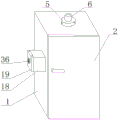
FIG. 1 is a schematic structural diagram of a portable intelligent measurement and control device for manufacturing according to the present invention;
FIG. 2 is a schematic diagram of a three-dimensional structure of a box body, a box cover, a cylindrical barrel, a servo motor, a rectangular barrel and a rectangular cover of the portable intelligent measurement and control device for manufacturing provided by the invention;
FIG. 3 is a schematic structural diagram of part A of a portable intelligent measurement and control device for manufacturing according to the present invention;
FIG. 4 is a schematic structural diagram of a part B of the portable intelligent measurement and control device for manufacturing according to the present invention;
fig. 5 is a schematic side view of the rectangular cover, the dust filter screen and the brush rod of the portable intelligent measurement and control device for manufacturing according to the present invention.
In the figure: the device comprises a box body 1, a box cover 2, universal wheels 3, a dust guard 4, a cylindrical barrel 5, a servo motor 6, an air suction fan 7, a controller 8, a rectangular box 9, a transverse shaft 10, an air suction shaft 11, a longitudinal shaft 12, a temperature sensor 13, a first bevel gear 14, a second bevel gear 15, a first linkage gear 16, a second linkage gear 17, a rectangular barrel 18, a rectangular cover 19, a cylindrical sleeve 20, a vertical guide rod 21, a hairbrush rod 22, a support rod 23, an air blowing shaft 24, an air blowing fan 25, a worm thread 26, a worm gear 27, a limit block 28, a circulating slide rod 29, a circulating groove 30, an air guide plate 31, a connecting ring 32, a multi-edge groove 33, a multi-edge rod 34, a connecting screw 35 and a dust filter screen 36.
Detailed Description
The technical solutions in the embodiments of the present invention will be clearly and completely described below with reference to the drawings in the embodiments of the present invention, and it is obvious that the described embodiments are only a part of the embodiments of the present invention, and not all of the embodiments.
Example one
Referring to fig. 1-5, a portable intelligent measurement and control device for manufacturing comprises a box body 1, a box cover 2 is connected to the outer side of the box body 1 in an overturning manner, two dust baffles 4 are fixedly mounted at the top of the box body 1, the dust baffles 14 can block dust, a controller 8 is fixedly connected to the top of the box body 1, a temperature sensor 13 is fixedly connected to the inner side of the box body 1, the temperature sensor 13 can be arranged to constantly monitor the internal temperature of the box body 1 and set the temperature value of the temperature sensor 13, a cylindrical barrel 5 is fixedly mounted at the top of the box body 1, an air suction shaft 11 is rotatably connected to the cylindrical barrel 5, a servo motor 6 is fixedly connected to the top of the cylindrical barrel 5, the servo motor 6 is connected to the controller 8, an output shaft of the servo motor 6 is fixedly mounted to the top of the air suction shaft 11, an air suction fan 7 is sleeved on the, the air blowing shaft 24 is rotatably mounted in the rectangular cylinder 18, an air blowing fan 25 is fixedly mounted on the outer side of the air blowing shaft 24, a linkage structure is connected between the air blowing shaft 24 and the air suction shaft 11, a plurality of air deflectors 31 are rotatably mounted in the rectangular cylinder 18, connecting rings 32 are fixedly mounted on the air deflectors 31, the connecting rings 32 are movably connected with a same vertical guide rod 21, the vertical guide rod 21 is vertically and slidably connected with the rectangular cylinder 18, two reciprocating structures are arranged in the rectangular cylinder 18, the two reciprocating structures are fixedly connected with the vertical guide rod 21, a rectangular cover 19 is fixedly connected to one side of the rectangular cylinder 18, a dust filter screen 36 is embedded in the central position of the rectangular cover 19, the dust filter screen 36 is used for filtering dust in air, a cleaning structure is rotatably connected to the central position of the dust filter screen 36, and is matched with the air blowing shaft.
In this embodiment, the linkage structure includes a transverse shaft 10, a longitudinal shaft 12, a first bevel gear 14, a second bevel gear 15, a first linkage gear 16 and a second linkage gear 17, the transverse shaft 10 is transversely and rotatably installed in the box 1, the longitudinal shaft 12 is vertically and rotatably installed at one side of the box 1, the second bevel gear 15 is fixedly installed at the top of the longitudinal shaft 12, the first bevel gear 14 is fixedly installed at one end of the transverse shaft 10, the first bevel gear 14 is engaged with the second bevel gear 15, the first linkage gear 16 is fixedly installed at the other end of the transverse shaft 10, the second linkage gear 17 is fixedly installed at the bottom end of the air suction shaft 11, the first linkage gear 16 is engaged with the second linkage gear 17, the air suction shaft 11 drives the transverse shaft 10 to rotate through the first linkage gear 16 and the second linkage gear 17, the transverse shaft 10 rotates the longitudinal shaft 12 due to the provision of two first bevel gears 14 and second bevel gears 15.
In this embodiment, a worm wheel 27 is fixedly mounted on the outer side of the longitudinal shaft 12, a worm thread 26 is formed on the outer side of the air blowing shaft 24, the worm thread 26 is meshed with the worm wheel 27, and the longitudinal shaft 12 drives the air blowing shaft 24 to rotate through the matching of the worm wheel 27 and the worm thread 26.
In this embodiment, the reciprocating structure includes a cylindrical sleeve 20 and circulating slide bars 29, the cylindrical sleeve 20 is fixedly sleeved on the outer side of the longitudinal shaft 12, the circulating slide bars 29 are fixedly installed with the vertical guide bars 21, the outer side of the cylindrical sleeve 20 is provided with circulating grooves 30, the vertical guide bars 21 are slidably connected with the circulating grooves 30, the longitudinal shaft 12 drives the two cylindrical sleeves 20 to rotate, the two cylindrical sleeves 20 respectively drive the two circulating slide bars 29 to slide back and forth along the vertical direction through the two circulating grooves 30, and the two circulating slide bars 29 drive the vertical guide bars 21 to slide back and forth along the vertical direction.
In this embodiment, fixed mounting has rectangle box 9 on the top inner wall of box 1, and the bottom fixed mounting of rectangle box 9 has a plurality of induction ports, and horizontal axle 10 rotates with rectangle box 9 to be connected, sets up that rectangle box 9 can be comprehensive siphons away the heat.
In this embodiment, the cleaning structure includes polygonal rod 34, connecting screw 35 and brush rod 22, polygonal rod 34 rotates and installs the central point at dust filter 36, connecting screw 35 threaded connection is on brush rod 22 and polygonal rod 34, brush rod 22 contacts with dust filter 36, polygonal groove 33 has been seted up to the one end of axle 24 of blowing, polygonal rod 34 and polygonal groove 33 sliding connection, axle 24 of blowing drives brush rod 22 through polygonal rod 34 and rotates, brush rod 22 cleans dust filter 36, when dismantling rectangular cover 19, polygonal rod 34 and polygonal groove 33 separate, when installing rectangular cover 19, polygonal rod 34 is connected with polygonal groove 33, do not influence the use.
In this embodiment, a support rod 23 is vertically and fixedly installed in the rectangular cylinder 18, and the air blowing shaft 24 is rotatably connected with the support rod 23.
In this embodiment, a plurality of limiting blocks 28 are fixedly installed on the outer side of the vertical guide rod 21, the connecting ring 32 is matched with the two corresponding limiting blocks 28, and the vertical guide rod 21 vertically moves to drive the plurality of air deflectors 31 to turn over back and forth through the plurality of limiting blocks 28.
In this embodiment, the bottom of box 1 is provided with four universal wheels 3 and all is provided with the brake block on four universal wheels 3, can conveniently remove box 1 through universal wheel 3, can die universal wheel 3 lock through the brake block.
Example two
Referring to fig. 1-5, a portable intelligent measurement and control device for manufacturing, comprising a box body 1, a box cover 2 connected with the outer side of the box body 1 in an overturning manner, two dust baffles 4 fixedly installed on the top of the box body 1 by welding, a controller 8 fixedly connected with the top of the box body 1 by screws, a temperature sensor 13 fixedly connected with the inside of the box body 1 by screws, a temperature sensor 13 capable of constantly monitoring the temperature inside the box body 1 and setting the temperature value of the temperature sensor 13, a cylinder 5 fixedly installed on the top of the box body 1 by welding, an air suction shaft 11 connected with the inside of the cylinder 5 in a rotating manner, a servo motor 6 fixedly connected with the top of the cylinder 5 by screws, the servo motor 6 connected with the controller 8, an output shaft of the servo motor 6 fixedly installed with the top of the air suction shaft 11 by welding, an air suction fan 7 sleeved on the outer side of the air suction shaft, one side of the box body 1 is fixedly communicated with a rectangular cylinder 18, a blowing shaft 24 is rotatably installed in the rectangular cylinder 18, a blowing fan 25 is fixedly installed on the outer side of the blowing shaft 24 through welding, a linkage structure is connected between the blowing shaft 24 and the suction shaft 11, a plurality of air deflectors 31 are rotatably installed in the rectangular cylinder 18, connecting rings 32 are fixedly installed on the air deflectors 31 through welding, the connecting rings 32 are movably connected with a same vertical guide rod 21, the vertical guide rod 21 is vertically and slidably connected with the rectangular cylinder 18, two reciprocating structures are arranged in the rectangular cylinder 18 and fixedly connected with the vertical guide rod 21 through screws, one side of the rectangular cylinder 18 is fixedly connected with a rectangular cover 19 through screws, a dust filter screen 36 is embedded in the central position of the rectangular cover 19 and used for filtering dust in air, and a cleaning structure is rotatably connected at the central position of the dust filter screen 36, the sweeping structure is matched with the blowing shaft 24.
In this embodiment, the linkage structure includes a transverse shaft 10, a longitudinal shaft 12, a first bevel gear 14, a second bevel gear 15, a first linkage gear 16 and a second linkage gear 17, the transverse shaft 10 is transversely rotatably installed in the box 1, the longitudinal shaft 12 is vertically rotatably installed at one side of the box 1, the second bevel gear 15 is fixedly installed at the top of the longitudinal shaft 12 by welding, the first bevel gear 14 is fixedly installed at one end of the transverse shaft 10 by welding, the first bevel gear 14 is engaged with the second bevel gear 15, the first linkage gear 16 is fixedly installed at the other end of the transverse shaft 10 by welding, the second linkage gear 17 is fixedly installed at the bottom end of the air suction shaft 11 by welding, the first linkage gear 16 is engaged with the second linkage gear 17, the air suction shaft 11 drives the transverse shaft 10 to rotate by the first linkage gear 16 and the second linkage gear 17, due to the two first bevel gears 14 and second linkage gears 15, so that the transverse shaft 10 rotates the longitudinal shaft 12.
In this embodiment, a worm wheel 27 is fixedly installed on the outer side of the longitudinal shaft 12 through welding, a worm thread 26 is formed on the outer side of the air blowing shaft 24, the worm thread 26 is meshed with the worm wheel 27, and the longitudinal shaft 12 drives the air blowing shaft 24 to rotate through the matching of the worm wheel 27 and the worm thread 26.
In this embodiment, the reciprocating structure includes a cylindrical sleeve 20 and circulating slide bars 29, the cylindrical sleeve 20 is fixedly sleeved on the outer side of the longitudinal shaft 12, the circulating slide bars 29 and the vertical guide bars 21 are fixedly installed by welding, a circulating groove 30 is formed in the outer side of the cylindrical sleeve 20, the vertical guide bars 21 are slidably connected with the circulating groove 30, the longitudinal shaft 12 drives the two cylindrical sleeves 20 to rotate, the two cylindrical sleeves 20 respectively drive the two circulating slide bars 29 to slide back and forth along the vertical direction through the two circulating grooves 30, and the two circulating slide bars 29 drive the vertical guide bars 21 to slide back and forth along the vertical direction.
In this embodiment, install rectangle box 9 through welded fastening on the top inner wall of box 1, there are a plurality of induction ports in the bottom of rectangle box 9 through welded fastening, and horizontal axle 10 rotates with rectangle box 9 to be connected, sets up that rectangle box 9 can be comprehensive siphons away the heat.
In this embodiment, the cleaning structure includes polygonal rod 34, connecting screw 35 and brush rod 22, polygonal rod 34 rotates and installs the central point at dust filter 36, connecting screw 35 threaded connection is on brush rod 22 and polygonal rod 34, brush rod 22 contacts with dust filter 36, polygonal groove 33 has been seted up to the one end of axle 24 of blowing, polygonal rod 34 and polygonal groove 33 sliding connection, axle 24 of blowing drives brush rod 22 through polygonal rod 34 and rotates, brush rod 22 cleans dust filter 36, be provided with the fluff on brush rod 22, when dismantling rectangular cover 19, polygonal rod 34 and polygonal groove 33 separate, when installing rectangular cover 19, polygonal rod 34 is connected with polygonal groove 33, do not influence the use.
In this embodiment, a support rod 23 is vertically and fixedly installed in the rectangular cylinder 18 by welding, and the air blowing shaft 24 is rotatably connected with the support rod 23.
In this embodiment, a plurality of limiting blocks 28 are fixedly installed on the outer side of the vertical guide rod 21 by welding, the connecting ring 32 is matched with the two corresponding limiting blocks 28, and the vertical guide rod 21 vertically moves to drive the plurality of air deflectors 31 to turn over back and forth through the plurality of limiting blocks 28.
In this embodiment, the bottom of box 1 is provided with four universal wheels 3 and all is provided with the brake block on four universal wheels 3, can conveniently remove box 1 through universal wheel 3, can die universal wheel 3 lock through the brake block.
In the embodiment, when the temperature monitoring device is used, the box body 1 can be conveniently moved through the universal wheels 3, the temperature inside the box body 1 can be monitored through the temperature sensor 13, the controller 8 controls the servo motor 6 to be started and closed, the servo motor 6 drives the air suction shaft 11 to rotate when being started, the air suction shaft 11 drives the air suction fan 7 to rotate, the air suction fan 7 forms an air suction state through the rectangular box 9, heat inside the box body 1 can be sucked out to the outer side of the box body 1, meanwhile, the air suction shaft 11 drives the transverse shaft 10 to rotate through the first linkage gear 16 and the second linkage gear 17, due to the arrangement of the two first bevel gears 14 and the second bevel gear 15, the transverse shaft 10 drives the longitudinal shaft 12 to rotate, the longitudinal shaft 12 drives the air blowing shaft 24 to rotate through the matching of the worm gear 27 and the worm threads 26, the air blowing shaft 24 drives the air blowing fan 25 to rotate to blow air inside the box body 1, the cooling effect is accelerated, the longitudinal shaft 12 drives the two cylindrical sleeves 20 to rotate, the two cylindrical sleeves 20 respectively drive the two circulating slide rods 29 to slide back and forth along the vertical direction through the two circulating grooves 30, the two circulating slide rods 29 drive the vertical guide rod 21 to slide back and forth along the vertical direction, the vertical guide rod 21 drives the air deflectors 31 to turn back and forth through the limit blocks 28, blowing air can be uniformly guided into the box body 1, so that heat dissipation is uniform, dust can be filtered on the outer side through the dust filter screen 36, the blowing shaft 24 drives the brush rod 22 to rotate through the multi-side rod 34, the brush rod 22 cleans the dust filter screen 36, dust attached to the outer side of the dust filter screen 36 can be swept down, the controller 8 controls the servo motor 6 to stop working until the temperature inside the box body 1 is proper, and the brush rod 22 can be detached and cleaned through detaching the connecting screw 35, the rectangular cover 19 can be detached, the dust filter screen 36 can be cleaned, the polygonal rod 34 is separated from the polygonal groove 33 when the rectangular cover 19 is detached, and the polygonal rod 34 is connected with the polygonal groove 33 when the rectangular cover 19 is installed, so that the use is not influenced.
The above description is only for the preferred embodiment of the present invention, but the scope of the present invention is not limited thereto, and any person skilled in the art should be considered to be within the technical scope of the present invention, and the technical solutions and the inventive concepts thereof according to the present invention should be equivalent or changed within the scope of the present invention.
Claims (9)
1. The utility model provides a portable measurement and control device for intelligent manufacturing, includes box (1), the outside upset of box (1) is connected with case lid (2), a serial communication port, the top fixed mounting of box (1) has two dust boards (4), the top fixedly connected with controller (8) of box (1), fixedly connected with temperature sensor (13) in box (1), the top fixed mounting of box (1) has a cylinder section of thick bamboo (5), cylinder section of thick bamboo (5) internal rotation is connected with air-breathing axle (11), the top fixedly connected with servo motor (6) of cylinder section of thick bamboo (5), servo motor (6) are connected with controller (8), the output shaft of servo motor (6) and the top fixed mounting of air-breathing axle (11), the outside cover of air-breathing axle (11) is equipped with air-breathing fan (7), one side fixed intercommunication of box (1) has a rectangle section of thick bamboo (18), an air blowing shaft (24) is rotatably mounted in a rectangular cylinder (18), an air blowing fan (25) is fixedly mounted on the outer side of the air blowing shaft (24), a linkage structure is connected between the air blowing shaft (24) and an air suction shaft (11), a plurality of air deflectors (31) are rotatably mounted in the rectangular cylinder (18), connecting rings (32) are fixedly mounted on the air deflectors (31), the connecting rings (32) are movably connected with a same vertical guide rod (21), the vertical guide rod (21) is vertically and slidably connected with the rectangular cylinder (18), two reciprocating structures are arranged in the rectangular cylinder (18), the two reciprocating structures are fixedly connected with the vertical guide rod (21), a rectangular cover (19) is fixedly connected to one side of the rectangular cylinder (18), a dust filter screen (36) is embedded in the central position of the rectangular cover (19), and a cleaning structure is rotatably connected to the central position of the dust filter screen (36), the cleaning structure is matched with the blowing shaft (24).
2. The portable intelligent measurement and control device for manufacturing according to claim 1, the linkage structure comprises a transverse shaft (10), a longitudinal shaft (12), a first bevel gear (14), a second bevel gear (15), a first linkage gear (16) and a second linkage gear (17), wherein the transverse shaft (10) is transversely installed in a box body (1) in a rotating mode, the longitudinal shaft (12) is vertically installed on one side of the box body (1) in a rotating mode, the second bevel gear (15) is fixedly installed at the top of the longitudinal shaft (12), the first bevel gear (14) is fixedly installed at one end of the transverse shaft (10), the first bevel gear (14) is meshed with the second bevel gear (15), the first linkage gear (16) is fixedly installed at the other end of the transverse shaft (10), the second linkage gear (17) is fixedly installed at the bottom end of an air suction shaft (11), and the first linkage gear (16) is meshed with the second linkage gear (17).
3. The portable intelligent measurement and control device for manufacturing according to claim 2, wherein a worm wheel (27) is fixedly mounted on the outer side of the longitudinal shaft (12), worm threads (26) are formed on the outer side of the air blowing shaft (24), and the worm threads (26) are meshed with the worm wheel (27).
4. The portable intelligent measurement and control device for manufacturing according to claim 1, wherein the reciprocating structure comprises a cylindrical sleeve (20) and a circulating slide rod (29), the cylindrical sleeve (20) is fixedly sleeved on the outer side of the longitudinal shaft (12), the circulating slide rod (29) is fixedly installed with a vertical guide rod (21), a circulating groove (30) is formed in the outer side of the cylindrical sleeve (20), and the vertical guide rod (21) is slidably connected with the circulating groove (30).
5. The portable intelligent measurement and control device for manufacturing according to claim 1, wherein a rectangular box (9) is fixedly installed on the inner wall of the top of the box body (1), a plurality of air suction ports are fixedly installed at the bottom of the rectangular box (9), and the transverse shaft (10) is rotatably connected with the rectangular box (9).
6. The portable intelligent measurement and control device for manufacturing according to claim 1, wherein the sweeping structure comprises a polygonal rod (34), a connecting screw (35) and a brush rod (22), the polygonal rod (34) is rotatably installed at the center of a dust filter screen (36), the connecting screw (35) is in threaded connection with the brush rod (22) and the polygonal rod (34), the brush rod (22) is in contact with the dust filter screen (36), a polygonal groove (33) is formed in one end of the air blowing shaft (24), and the polygonal rod (34) is in sliding connection with the polygonal groove (33).
7. The portable intelligent measurement and control device for manufacturing according to claim 1, wherein a support rod (23) is vertically and fixedly installed in the rectangular cylinder (18), and the air blowing shaft (24) is rotatably connected with the support rod (23).
8. The portable intelligent measurement and control device for manufacturing according to claim 1, wherein a plurality of limiting blocks (28) are fixedly mounted on the outer side of the vertical guide rod (21), and the connecting ring (32) is matched with the two corresponding limiting blocks (28).
9. The portable intelligent measurement and control device for manufacturing according to claim 1, wherein four universal wheels (3) are arranged at the bottom of the box body (1), and brake pads are arranged on the four universal wheels (3).
Priority Applications (1)
| Application Number | Priority Date | Filing Date | Title |
|---|---|---|---|
| CN202010280058.1A CN111478208B (en) | 2020-04-10 | 2020-04-10 | Portable intelligent measurement and control device for manufacturing |
Applications Claiming Priority (1)
| Application Number | Priority Date | Filing Date | Title |
|---|---|---|---|
| CN202010280058.1A CN111478208B (en) | 2020-04-10 | 2020-04-10 | Portable intelligent measurement and control device for manufacturing |
Publications (2)
| Publication Number | Publication Date |
|---|---|
| CN111478208A true CN111478208A (en) | 2020-07-31 |
| CN111478208B CN111478208B (en) | 2022-02-25 |
Family
ID=71751753
Family Applications (1)
| Application Number | Title | Priority Date | Filing Date |
|---|---|---|---|
| CN202010280058.1A Active CN111478208B (en) | 2020-04-10 | 2020-04-10 | Portable intelligent measurement and control device for manufacturing |
Country Status (1)
| Country | Link |
|---|---|
| CN (1) | CN111478208B (en) |
Cited By (5)
| Publication number | Priority date | Publication date | Assignee | Title |
|---|---|---|---|---|
| CN112188806A (en) * | 2020-10-09 | 2021-01-05 | 淮南联合大学(安徽广播电视大学淮南分校淮南职工大学) | Heat radiation structure of power electronic component |
| CN112531519A (en) * | 2020-11-19 | 2021-03-19 | 徐克山 | Electric power cabinet with dampproofing high temperature function of preventing |
| CN112698059A (en) * | 2020-12-14 | 2021-04-23 | 国网山东省电力公司烟台供电公司 | Detection apparatus for parasitic loop of direct current system |
| CN113311367A (en) * | 2021-06-04 | 2021-08-27 | 张晓彤 | Electrical experiment table wiring correct and incorrect monitoring system |
| CN115064955A (en) * | 2022-07-05 | 2022-09-16 | 扬州德云电气设备集团有限公司 | High-low voltage switch cabinet with waterproof dustproof function |
Citations (14)
| Publication number | Priority date | Publication date | Assignee | Title |
|---|---|---|---|---|
| CN101399171A (en) * | 2007-09-25 | 2009-04-01 | 大日本网屏制造株式会社 | Method of forming alignment mark |
| CN204304271U (en) * | 2014-12-18 | 2015-04-29 | 镇江香江云动力科技有限公司 | Heat radiation and the dust removal integrated plant of cabinet Based Intelligent Control is equipped for switch |
| CN106972380A (en) * | 2017-05-16 | 2017-07-21 | 国网河南省电力公司平顶山供电公司 | A kind of safety-protection system power equipment |
| CN107591706A (en) * | 2017-09-20 | 2018-01-16 | 黄思宜 | One kind swings blast type heat radiating type damping power distribution cabinet |
| CN107681510A (en) * | 2017-11-08 | 2018-02-09 | 王宏亮 | A kind of electric power cabinet with damping and high-efficient radiating function |
| CN108390289A (en) * | 2018-04-26 | 2018-08-10 | 阜阳盛东智能制造技术研发有限公司 | A kind of portable intelligent manufacture measure and control device |
| CN108736351A (en) * | 2018-07-25 | 2018-11-02 | 吴鑫锋 | A kind of adjustable heat radiating type switchgear |
| CN208143074U (en) * | 2018-04-23 | 2018-11-23 | 监利申联纺织有限公司 | A kind of spinning frame frequency converter cooling device |
| CN109788726A (en) * | 2019-03-25 | 2019-05-21 | 广州市易度软件开发有限公司 | A kind of radiator of big data all-in-one machine |
| CN209120570U (en) * | 2018-08-27 | 2019-07-16 | 广东赛晔信息技术有限公司 | A kind of electronic equipment radiator |
| CN209730457U (en) * | 2019-06-21 | 2019-12-03 | 吴叶烁 | A kind of radiator of low-voltage distribution apparatus |
| CN110559780A (en) * | 2019-09-11 | 2019-12-13 | 大同新成新材料股份有限公司 | Carbon fiber production waste gas treatment device and method |
| CN110867759A (en) * | 2019-11-28 | 2020-03-06 | 中铁十六局集团有限公司 | Subway construction is with high-efficient heat dissipation block terminal |
| CN210275005U (en) * | 2019-07-29 | 2020-04-07 | 河北达信电子科技有限公司 | Magnetic detection module with waterproof shell |
-
2020
- 2020-04-10 CN CN202010280058.1A patent/CN111478208B/en active Active
Patent Citations (14)
| Publication number | Priority date | Publication date | Assignee | Title |
|---|---|---|---|---|
| CN101399171A (en) * | 2007-09-25 | 2009-04-01 | 大日本网屏制造株式会社 | Method of forming alignment mark |
| CN204304271U (en) * | 2014-12-18 | 2015-04-29 | 镇江香江云动力科技有限公司 | Heat radiation and the dust removal integrated plant of cabinet Based Intelligent Control is equipped for switch |
| CN106972380A (en) * | 2017-05-16 | 2017-07-21 | 国网河南省电力公司平顶山供电公司 | A kind of safety-protection system power equipment |
| CN107591706A (en) * | 2017-09-20 | 2018-01-16 | 黄思宜 | One kind swings blast type heat radiating type damping power distribution cabinet |
| CN107681510A (en) * | 2017-11-08 | 2018-02-09 | 王宏亮 | A kind of electric power cabinet with damping and high-efficient radiating function |
| CN208143074U (en) * | 2018-04-23 | 2018-11-23 | 监利申联纺织有限公司 | A kind of spinning frame frequency converter cooling device |
| CN108390289A (en) * | 2018-04-26 | 2018-08-10 | 阜阳盛东智能制造技术研发有限公司 | A kind of portable intelligent manufacture measure and control device |
| CN108736351A (en) * | 2018-07-25 | 2018-11-02 | 吴鑫锋 | A kind of adjustable heat radiating type switchgear |
| CN209120570U (en) * | 2018-08-27 | 2019-07-16 | 广东赛晔信息技术有限公司 | A kind of electronic equipment radiator |
| CN109788726A (en) * | 2019-03-25 | 2019-05-21 | 广州市易度软件开发有限公司 | A kind of radiator of big data all-in-one machine |
| CN209730457U (en) * | 2019-06-21 | 2019-12-03 | 吴叶烁 | A kind of radiator of low-voltage distribution apparatus |
| CN210275005U (en) * | 2019-07-29 | 2020-04-07 | 河北达信电子科技有限公司 | Magnetic detection module with waterproof shell |
| CN110559780A (en) * | 2019-09-11 | 2019-12-13 | 大同新成新材料股份有限公司 | Carbon fiber production waste gas treatment device and method |
| CN110867759A (en) * | 2019-11-28 | 2020-03-06 | 中铁十六局集团有限公司 | Subway construction is with high-efficient heat dissipation block terminal |
Cited By (6)
| Publication number | Priority date | Publication date | Assignee | Title |
|---|---|---|---|---|
| CN112188806A (en) * | 2020-10-09 | 2021-01-05 | 淮南联合大学(安徽广播电视大学淮南分校淮南职工大学) | Heat radiation structure of power electronic component |
| CN112531519A (en) * | 2020-11-19 | 2021-03-19 | 徐克山 | Electric power cabinet with dampproofing high temperature function of preventing |
| CN112698059A (en) * | 2020-12-14 | 2021-04-23 | 国网山东省电力公司烟台供电公司 | Detection apparatus for parasitic loop of direct current system |
| CN113311367A (en) * | 2021-06-04 | 2021-08-27 | 张晓彤 | Electrical experiment table wiring correct and incorrect monitoring system |
| CN115064955A (en) * | 2022-07-05 | 2022-09-16 | 扬州德云电气设备集团有限公司 | High-low voltage switch cabinet with waterproof dustproof function |
| CN115064955B (en) * | 2022-07-05 | 2023-11-10 | 扬州德云电气设备集团有限公司 | High-low voltage switch cabinet with waterproof and dustproof functions |
Also Published As
| Publication number | Publication date |
|---|---|
| CN111478208B (en) | 2022-02-25 |
Similar Documents
| Publication | Publication Date | Title |
|---|---|---|
| CN111478208B (en) | Portable intelligent measurement and control device for manufacturing | |
| CN210725871U (en) | Cooling device for server cabinet of computer room | |
| CN218722544U (en) | Energy-saving refrigeration house refrigerating unit | |
| CN111229662A (en) | Ash removal device for transformer bearing seat of transformer substation | |
| CN217594133U (en) | Generator with self-cleaning air inlet | |
| CN114362427B (en) | Motor with uniformly distributed ventilation type protective cover structure | |
| CN215918473U (en) | Cleaning device for high-voltage power distribution cabinet | |
| CN220585756U (en) | Dustproof heat radiation structure | |
| CN209133948U (en) | A kind of wind-cooling heat dissipating power cabinet | |
| CN209212504U (en) | A kind of cooling device of vacuum pump | |
| CN216126922U (en) | Motor stator core production grinding device | |
| CN117134216B (en) | High-voltage electrical cabinet | |
| CN218166269U (en) | High-voltage board with dust removal function | |
| CN215955844U (en) | Switch board with heat dissipation function | |
| CN213400775U (en) | Power transformer fixing equipment | |
| CN219288054U (en) | Computer room heat radiation equipment | |
| CN213818751U (en) | High-efficiency energy-saving ventilation device for electrical equipment | |
| CN219087509U (en) | Outdoor installation cabinet with waterproof function for cooling and heating equipment | |
| CN216026746U (en) | Dust collector for electric power system secondary protection | |
| CN219780640U (en) | Multifunctional temperature control device for power dispatching workbench | |
| CN220209637U (en) | Mechanical and electrical distribution box | |
| CN216774535U (en) | Inside cooling system of motor | |
| CN218006107U (en) | Frequency converter protection device | |
| CN210638198U (en) | High-efficiency energy-saving air-cooling module unit | |
| CN216845032U (en) | Dust collection and insulation device for distribution room |
Legal Events
| Date | Code | Title | Description |
|---|---|---|---|
| PB01 | Publication | ||
| PB01 | Publication | ||
| SE01 | Entry into force of request for substantive examination | ||
| SE01 | Entry into force of request for substantive examination | ||
| GR01 | Patent grant | ||
| GR01 | Patent grant |