CN111469555B - Recording head element and ink jet recording apparatus - Google Patents
Recording head element and ink jet recording apparatus Download PDFInfo
- Publication number
- CN111469555B CN111469555B CN202010063434.1A CN202010063434A CN111469555B CN 111469555 B CN111469555 B CN 111469555B CN 202010063434 A CN202010063434 A CN 202010063434A CN 111469555 B CN111469555 B CN 111469555B
- Authority
- CN
- China
- Prior art keywords
- ink
- recording head
- flow path
- head element
- element according
- Prior art date
- Legal status (The legal status is an assumption and is not a legal conclusion. Google has not performed a legal analysis and makes no representation as to the accuracy of the status listed.)
- Active
Links
- 238000010438 heat treatment Methods 0.000 claims abstract description 18
- 239000010408 film Substances 0.000 claims description 21
- 239000010409 thin film Substances 0.000 claims description 11
- 239000000976 ink Substances 0.000 description 210
- 230000008859 change Effects 0.000 description 12
- 238000004140 cleaning Methods 0.000 description 11
- 230000008878 coupling Effects 0.000 description 9
- 238000010168 coupling process Methods 0.000 description 9
- 238000005859 coupling reaction Methods 0.000 description 9
- 238000003860 storage Methods 0.000 description 8
- 230000001105 regulatory effect Effects 0.000 description 7
- 238000012423 maintenance Methods 0.000 description 6
- 239000000463 material Substances 0.000 description 6
- 238000010586 diagram Methods 0.000 description 4
- 239000012528 membrane Substances 0.000 description 3
- 238000010926 purge Methods 0.000 description 3
- 239000000758 substrate Substances 0.000 description 3
- 230000009471 action Effects 0.000 description 2
- 239000000919 ceramic Substances 0.000 description 2
- 230000015654 memory Effects 0.000 description 2
- 239000002184 metal Substances 0.000 description 2
- 229920000139 polyethylene terephthalate Polymers 0.000 description 2
- 239000005020 polyethylene terephthalate Substances 0.000 description 2
- 239000011347 resin Substances 0.000 description 2
- 229920005989 resin Polymers 0.000 description 2
- 239000000470 constituent Substances 0.000 description 1
- 238000007599 discharging Methods 0.000 description 1
- 230000000694 effects Effects 0.000 description 1
- 230000017525 heat dissipation Effects 0.000 description 1
- 230000006872 improvement Effects 0.000 description 1
- 239000007788 liquid Substances 0.000 description 1
- 238000004519 manufacturing process Methods 0.000 description 1
- 238000012986 modification Methods 0.000 description 1
- 230000004048 modification Effects 0.000 description 1
- -1 polyethylene terephthalate Polymers 0.000 description 1
- 239000004065 semiconductor Substances 0.000 description 1
- 238000011144 upstream manufacturing Methods 0.000 description 1
Images


Classifications
-
- B—PERFORMING OPERATIONS; TRANSPORTING
- B41—PRINTING; LINING MACHINES; TYPEWRITERS; STAMPS
- B41J—TYPEWRITERS; SELECTIVE PRINTING MECHANISMS, i.e. MECHANISMS PRINTING OTHERWISE THAN FROM A FORME; CORRECTION OF TYPOGRAPHICAL ERRORS
- B41J2/00—Typewriters or selective printing mechanisms characterised by the printing or marking process for which they are designed
- B41J2/005—Typewriters or selective printing mechanisms characterised by the printing or marking process for which they are designed characterised by bringing liquid or particles selectively into contact with a printing material
- B41J2/01—Ink jet
- B41J2/135—Nozzles
- B41J2/14—Structure thereof only for on-demand ink jet heads
- B41J2/14016—Structure of bubble jet print heads
- B41J2/14145—Structure of the manifold
-
- B—PERFORMING OPERATIONS; TRANSPORTING
- B41—PRINTING; LINING MACHINES; TYPEWRITERS; STAMPS
- B41J—TYPEWRITERS; SELECTIVE PRINTING MECHANISMS, i.e. MECHANISMS PRINTING OTHERWISE THAN FROM A FORME; CORRECTION OF TYPOGRAPHICAL ERRORS
- B41J2/00—Typewriters or selective printing mechanisms characterised by the printing or marking process for which they are designed
- B41J2/005—Typewriters or selective printing mechanisms characterised by the printing or marking process for which they are designed characterised by bringing liquid or particles selectively into contact with a printing material
- B41J2/01—Ink jet
- B41J2/135—Nozzles
- B41J2/14—Structure thereof only for on-demand ink jet heads
- B41J2/14016—Structure of bubble jet print heads
- B41J2/14088—Structure of heating means
-
- B—PERFORMING OPERATIONS; TRANSPORTING
- B41—PRINTING; LINING MACHINES; TYPEWRITERS; STAMPS
- B41J—TYPEWRITERS; SELECTIVE PRINTING MECHANISMS, i.e. MECHANISMS PRINTING OTHERWISE THAN FROM A FORME; CORRECTION OF TYPOGRAPHICAL ERRORS
- B41J2/00—Typewriters or selective printing mechanisms characterised by the printing or marking process for which they are designed
- B41J2/005—Typewriters or selective printing mechanisms characterised by the printing or marking process for which they are designed characterised by bringing liquid or particles selectively into contact with a printing material
- B41J2/01—Ink jet
- B41J2/135—Nozzles
- B41J2/165—Prevention or detection of nozzle clogging, e.g. cleaning, capping or moistening for nozzles
- B41J2/16505—Caps, spittoons or covers for cleaning or preventing drying out
-
- B—PERFORMING OPERATIONS; TRANSPORTING
- B41—PRINTING; LINING MACHINES; TYPEWRITERS; STAMPS
- B41J—TYPEWRITERS; SELECTIVE PRINTING MECHANISMS, i.e. MECHANISMS PRINTING OTHERWISE THAN FROM A FORME; CORRECTION OF TYPOGRAPHICAL ERRORS
- B41J2/00—Typewriters or selective printing mechanisms characterised by the printing or marking process for which they are designed
- B41J2/005—Typewriters or selective printing mechanisms characterised by the printing or marking process for which they are designed characterised by bringing liquid or particles selectively into contact with a printing material
- B41J2/01—Ink jet
- B41J2/135—Nozzles
- B41J2/165—Prevention or detection of nozzle clogging, e.g. cleaning, capping or moistening for nozzles
- B41J2/16517—Cleaning of print head nozzles
- B41J2/16535—Cleaning of print head nozzles using wiping constructions
-
- B—PERFORMING OPERATIONS; TRANSPORTING
- B41—PRINTING; LINING MACHINES; TYPEWRITERS; STAMPS
- B41J—TYPEWRITERS; SELECTIVE PRINTING MECHANISMS, i.e. MECHANISMS PRINTING OTHERWISE THAN FROM A FORME; CORRECTION OF TYPOGRAPHICAL ERRORS
- B41J2/00—Typewriters or selective printing mechanisms characterised by the printing or marking process for which they are designed
- B41J2/005—Typewriters or selective printing mechanisms characterised by the printing or marking process for which they are designed characterised by bringing liquid or particles selectively into contact with a printing material
- B41J2/01—Ink jet
- B41J2/17—Ink jet characterised by ink handling
- B41J2/175—Ink supply systems ; Circuit parts therefor
-
- B—PERFORMING OPERATIONS; TRANSPORTING
- B41—PRINTING; LINING MACHINES; TYPEWRITERS; STAMPS
- B41J—TYPEWRITERS; SELECTIVE PRINTING MECHANISMS, i.e. MECHANISMS PRINTING OTHERWISE THAN FROM A FORME; CORRECTION OF TYPOGRAPHICAL ERRORS
- B41J2/00—Typewriters or selective printing mechanisms characterised by the printing or marking process for which they are designed
- B41J2/005—Typewriters or selective printing mechanisms characterised by the printing or marking process for which they are designed characterised by bringing liquid or particles selectively into contact with a printing material
- B41J2/01—Ink jet
- B41J2/17—Ink jet characterised by ink handling
- B41J2/19—Ink jet characterised by ink handling for removing air bubbles
-
- B—PERFORMING OPERATIONS; TRANSPORTING
- B41—PRINTING; LINING MACHINES; TYPEWRITERS; STAMPS
- B41J—TYPEWRITERS; SELECTIVE PRINTING MECHANISMS, i.e. MECHANISMS PRINTING OTHERWISE THAN FROM A FORME; CORRECTION OF TYPOGRAPHICAL ERRORS
- B41J2/00—Typewriters or selective printing mechanisms characterised by the printing or marking process for which they are designed
- B41J2/005—Typewriters or selective printing mechanisms characterised by the printing or marking process for which they are designed characterised by bringing liquid or particles selectively into contact with a printing material
- B41J2/01—Ink jet
- B41J2/17—Ink jet characterised by ink handling
- B41J2/195—Ink jet characterised by ink handling for monitoring ink quality
-
- B—PERFORMING OPERATIONS; TRANSPORTING
- B41—PRINTING; LINING MACHINES; TYPEWRITERS; STAMPS
- B41J—TYPEWRITERS; SELECTIVE PRINTING MECHANISMS, i.e. MECHANISMS PRINTING OTHERWISE THAN FROM A FORME; CORRECTION OF TYPOGRAPHICAL ERRORS
- B41J2/00—Typewriters or selective printing mechanisms characterised by the printing or marking process for which they are designed
- B41J2/005—Typewriters or selective printing mechanisms characterised by the printing or marking process for which they are designed characterised by bringing liquid or particles selectively into contact with a printing material
- B41J2/01—Ink jet
- B41J2/21—Ink jet for multi-colour printing
- B41J2/2103—Features not dealing with the colouring process per se, e.g. construction of printers or heads, driving circuit adaptations
Landscapes
- Engineering & Computer Science (AREA)
- Quality & Reliability (AREA)
- Ink Jet (AREA)
Abstract
The invention provides a recording head element and an ink jet recording apparatus. The recording head element includes a recording head, a tubular member, and an ink supply portion. The recording head is used to eject ink. The tubular member supplies ink to the recording head. The ink supply unit supplies ink to the tubular member. The ink supply section has a flow path through which ink flows toward one end of the tubular member. The ink supply section has a heating member located beside the flow path.
Description
Technical Field
The invention relates to a recording head element and an ink jet recording apparatus.
Background
The inkjet recording apparatus has a nozzle surface on which a plurality of nozzle holes are formed. An ink jet recording apparatus ejects ink from all or a part of a plurality of nozzle holes to record an image on a recording medium. The viscosity of the ink becomes high in a low-temperature environment. Therefore, the ejection performance of the ink may not reach the expected performance in a low-temperature environment. In view of the above, a configuration has been proposed in which the ink is heated by a heater before being discharged.
Disclosure of Invention
However, there is still room for improvement in the structure for increasing the ink temperature.
The present invention has been made in view of the above problems, and an object thereof is to provide a recording head element and an ink jet recording apparatus capable of efficiently raising the temperature of ink.
A recording head element of the present invention includes a recording head, a tubular member, and an ink supply portion. The recording head is used for ejecting ink. The tubular member supplies the ink to the recording head. The ink supply section supplies the ink to the tubular member. The ink supply section has a flow path through which the ink flows toward one end of the tubular member. The ink supply section includes a heating member disposed beside the flow path.
The ink jet recording apparatus of the present invention includes the above-described recording head element.
According to the recording head element and the inkjet recording apparatus of the present invention, the ink temperature can be efficiently raised.
Drawings
Fig. 1 is a perspective view of a recording head element according to an embodiment of the present invention.
Fig. 2 is a perspective view of a recording head element according to an embodiment of the present invention.
Fig. 3 is a perspective view of a flow rate adjustment member according to an embodiment of the present invention.
Fig. 4 is a plan view of a flow rate adjustment member according to an embodiment of the present invention.
Fig. 5 is a partial perspective view of a recording head element according to an embodiment of the present invention.
Fig. 6 is a structural diagram of an ink supply unit according to an embodiment of the present invention.
Fig. 7 is a structural diagram of an inkjet recording apparatus according to an embodiment of the present invention.
Detailed Description
Hereinafter, embodiments of the present invention will be described with reference to the drawings. However, in the drawings, the same reference numerals are used for the same or corresponding portions, and the description thereof will not be repeated. Note that, in some cases, the description of the parts that will be described repeatedly will be omitted as appropriate. For convenience of understanding, the front-back direction, the up-down direction, and the left-right direction are shown in the drawings, but the directions of the recording head element and the inkjet recording apparatus according to the present invention during manufacturing and during use are not limited thereto.
First, the recording head element 1 of the present embodiment will be described with reference to fig. 1 and 2. Fig. 1 and 2 are perspective views of a recording head element 1 according to the present embodiment. Specifically, fig. 1 is a recording head element 1 viewed from obliquely above right front. Fig. 2 is a view of the recording head element 1 viewed obliquely from right front below. As shown in fig. 1 and 2, the recording head element 1 of the present embodiment is provided with 3 recording heads 2, 3 supply tubular members 3, 3 circulation tubular members 4, a flow rate adjusting member 6, 3 first coupling members 51, and 3 second coupling members 52.
The 3 recording heads 2 each eject ink. Specifically, the 3 recording heads 2 eject ink of the same color. Each recording head 2 extends in the left-right direction. In the present embodiment, the 3 recording heads 2 include first to third recording heads 2a to 2 c. The first to third recording heads 2a to 2c are arranged in a staggered manner in the left-right direction. Specifically, the second recording head 2b is disposed on the rear side of the first recording head 2a and the third recording head 2 c.
Each of the 3 recording heads 2 has a nozzle face 21 (fig. 2). Each of the recording heads 2 ejects ink from the nozzle surface 21. Specifically, a plurality of nozzle holes are formed in the nozzle surface 21, and ink is ejected from the nozzle holes.
The 3 supply tubular members 3 supply ink to the 3 recording heads 2, respectively. One end (lower end) of each of the 3 supply tubular members 3 is connected to the left end of the corresponding recording head 2. The 3 supply tubular members 3 each extend upward from the corresponding recording head 2. In the present embodiment, the 3 supply tubular members 3 include a first supply tubular member 3a to a third supply tubular member 3 c. The first supply tubular member 3a supplies ink to the first recording head 2 a. The second supply tubular member 3b supplies ink to the second recording head 2b (fig. 2). The third supply tubular member 3c supplies ink to the third recording head 2 c.
One end (lower end) of each of the 3 circulating tubular members 4 is connected to the right end portion of the corresponding recording head 2. Each of the 3 circulation tubular members 4 extends upward from the corresponding recording head 2. In the present embodiment, the 3 circulation tubular members 4 include the first circulation tubular member 4a to the third circulation tubular member 4 c. The first circulation tubular member 4a is connected to the first recording head 2 a. The second circulation tubular member 4b is connected to the second recording head 2 b. The third circulating tubular member 4c is connected to the third recording head 2 c.
During the cleaning operation, ink flows from the corresponding recording head 2 into each circulation pipe member 4. The cleaning action is as follows: the ink is pressurized to such an extent that the ink is not ejected from the nozzle holes, and the ink is supplied to the recording head 2. The purpose of the purging action is, for example, to remove air bubbles from the ink. When the cleaning operation is performed, ink is discharged from each of the 3 recording heads 2 into the corresponding circulating tubular member 4. Specifically, the ink flowing from the supply tubular member 3 into the recording head 2 flows out into the circulation tubular member 4 through a circulation flow path formed inside the recording head 2. At this time, the air bubbles flow into the recording head 2 from the supply tubular member 3 together with the ink. The bubbles flow out to the circulation tubular member 4 through the circulation flow path together with the ink. The ink and the air bubbles flowing into each circulation tubular member 4 are returned to the ink supply unit 15 described with reference to fig. 6.
The flow rate adjusting member 6 is disposed above the 3 recording heads 2. The flow rate adjusting member 6 supplies ink to the 3 supply tubular members 3. As a result, the ink is supplied to the 3 recording heads 2 through the 3 supply tubular members 3. The flow rate adjusting member 6 is an example of an ink supply portion.
The 3 first coupling members 51 respectively couple the other ends (upper ends) of the 3 supply tubular members 3 to the flow rate adjusting member 6. The 3 second coupling parts 52 respectively couple the other ends (upper ends) of the 3 circulation tubular parts 4 to the circulation pipes 164 described with reference to fig. 6.
Next, the flow rate adjusting member 6 of the present embodiment will be further described with reference to fig. 1. As shown in fig. 1, the flow rate adjusting member 6 has a base 61, a flow path 62, and an ink inflow portion 63.
The base body 61 is a plate-like member. The base 61 extends in the left-right direction. In other words, the base 61 extends in the direction in which the 3 recording heads 2 are aligned. The base 61 of the present embodiment is a metal member. The base 61 has an upper wall 611.
The ink inflow portion 63 is provided on the upper wall 611 of the base body 61. The ink inflow portion 63 is provided substantially at the center of the base 61 in the lateral direction. The ink is supplied from the ink supply unit 15 described with reference to fig. 6 to the ink inflow portion 63.
The flow path 62 is formed inside the base 61. The base body 61 has an inner wall 612 inside thereof, and the inner wall 612 constitutes a side surface of the flow path 62. The ink flows into the flow path 62 from the ink inflow portion 63. The flow path 62 guides the ink to the other end (upper end) of each of the 3 supply tubular members 3. In addition, a part of the upper wall 611 of the base 61 constitutes the top surface of the flow path 62. The upper wall 611 is an example of a wall portion.
Next, the flow rate adjusting member 6 of the present embodiment will be further described with reference to fig. 3. Fig. 3 is a perspective view of the flow rate adjustment member 6 according to the present embodiment. Specifically, fig. 3 is a view of the flow rate adjustment member 6 viewed obliquely from the front right and downward. As shown in fig. 3, the base 61 has a lower wall 613. A part of the lower wall 613 of the base 61 constitutes the bottom surface of the flow path 62. The flow rate regulating member 6 has 3 ink outflow portions 64, and the 3 ink outflow portions 64 are provided on the lower wall 613 of the base body 61.
Each of the 3 ink outflow portions 64 protrudes downward from the lower wall 613 of the base body 61. The 3 ink outflow portions 64 communicate with the other ends (upper ends) of the 3 supply tubular members 3 described with reference to fig. 1 and 2, respectively. The flow rate regulating member 6 causes ink to flow out from the 3 ink outflow portions 64, and supplies the ink to the 3 supply tubular members 3.
Specifically, by the 3 first coupling members 51 described with reference to fig. 1 and 2, the 3 ink outflow portions 64 are each coupled to the other end of the 3 supply tubular members 3. In the present embodiment, the 3 ink outflow portions 64 include the first to third ink outflow portions 64a to 64 c. The first ink outflow portion 64a is coupled to the other end of the first supply tubular member 3a by 1 of the 3 first coupling members 51. Thereby, the ink is supplied from the first ink outflow portion 64a to the first supply tubular member 3 a. The second ink outflow portion 64b is coupled to the other end of the second supply tubular member 3b by 1 of the 3 first coupling members 51. Thereby, the ink is supplied from the second ink outflow portion 64b to the second supply tubular member 3 b. The third ink outflow portion 64c is coupled to the other end of the third supply tubular member 3c by 1 of the 3 first coupling members 51. Thereby, the ink is supplied from the third ink outflow portion 64c to the third supply tubular member 3 c.
As shown in fig. 3, the flow path 62 includes a first flow path 62a and a second flow path 62 b. Specifically, the flow path 62 extends in the left-right direction. The first flow path 62a is a left side portion of the flow path 62 at substantially the center in the left-right direction. The second flow path 62b is a right portion of the flow path 62 at substantially the center in the left-right direction. One end of the first flow path 62a communicates with the upper end opening of the first ink outflow portion 64 a. One end of the second flow path 62b communicates with the upper end opening of the third ink outflow portion 64 c. In the following description, a substantial center of the flow path 62 in the left-right direction may be referred to as "a center of the flow path 62".
The ink supplied to the ink inflow portion 63 described with reference to fig. 1 flows out from the ink inflow portion 63 to the center of the flow path 62. The ink flowing out of the ink inflow portion 63 to the flow path 62 partially flows along the first flow path 62 a. The ink flowing out of the ink inflow portion 63 to the flow path 62 flows along the second flow path 62 b. The remaining part of the ink flowing out of the ink inflow portion 63 to the flow path 62 flows to the upper end opening of the second ink outflow portion 64b through the flow path 62.
The ink flowing into the first flow path 62a flows in the first flow direction D1 to the upper end opening of the first ink outflow portion 64 a. The ink flowing into the second channel 62b flows in the second flow direction D2 to the upper end opening of the third ink outflow portion 64 c. As a result, the ink flows from the first channel 62a into the first ink outflow portion 64a, and the ink is supplied to the first recording head 2a described with reference to fig. 1 and 2. Similarly, the ink flows from the second channel 62b into the third ink outflow portion 64c, and the ink is supplied to the third recording head 2c described with reference to fig. 1 and 2.
As shown in fig. 3, the lower wall 613 of the base body 61 has an opening 614. The opening 614 opens to the first flow path 62 a. The flow regulating member 6 also has a membrane 65 covering the opening 614. The membrane 65 extends along the flow path 62. Specifically, the film 65 is a part of the bottom surface of the flow path 62. Specifically, the film 65 is a part of the bottom surface of the first channel 62 a. The film 65 is an example of a film member.
The film 65 has elasticity. The film 65 is, for example, a PET (polyethylene terephthalate) film as a base material. By forming the film 65 as a part of the surface constituting the flow path 62, the pressure change of the ink can be absorbed by the film 65. In other words, the amount of pressure change of the ink is suppressed by the film 65. Specifically, the film 65 bulges or dents according to the pressure change of the ink. As a result, the pressure change of the ink is absorbed. The length of the film 65 along the flow path 62 is not particularly limited as long as the film 65 can absorb the pressure change of the ink.
The pressure change of the ink may cause the ink to drop from the nozzle when the ink ejection is stopped. Further, the pressure change of the ink may cause the ink to flow into at least 1 of the 3 circulation tubular members 4 described with reference to fig. 1 and 2 when the ink stops being discharged.
Specifically, the recording head 2 ejects ink in accordance with an image to be recorded. In detail, the image includes a printed portion and a non-printed portion. The recording head 2 ejects ink corresponding to the printing portion and stops ink ejection corresponding to the non-printing portion. The pressure change of the ink is generated when the ink ejection is stopped corresponding to the non-printing portion. More specifically, the recording head 2 includes a piezoelectric element. The ink is ejected by driving the piezoelectric element. The ink ejection is stopped by stopping the driving of the piezoelectric element. The pressure change of the ink is caused by stopping the driving of the piezoelectric element.
According to the present embodiment, the film 65 absorbs the pressure change of the ink. Therefore, when the ink stops being ejected, the ink does not easily drop from the nozzle. Further, when the ink ejection is stopped, the ink does not easily flow into the 3 circulation tubular members 4 described with reference to fig. 1 and 2.
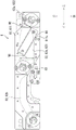
Next, the flow rate adjusting member 6 of the present embodiment will be further described with reference to fig. 4. Fig. 4 is a plan view of the flow rate adjustment member 6 according to the present embodiment. As shown in fig. 4, the flow rate regulating member 6 has a heater 66 beside the flow path 62. The heater 66 is an example of a heating member. The heater 66 is, for example, a ceramic heater. The ceramic heater generates heat by being energized.
As described above, the recording head element 1 of the present embodiment is explained with reference to fig. 1 to 4. According to the present embodiment, the heater 66 is located beside the flow path 62. Therefore, the ink flowing through the flow path 62 can be efficiently heated by the heater 66. As a result, the temperature of the ink can be efficiently increased before the ink is ejected. Thus, according to the present embodiment, the viscosity of the ink can be suppressed from increasing even in a low-temperature environment. As a result, the possibility that the ejection performance of the ink may not reach the expected performance can be reduced.
Next, the flow rate adjusting member 6 of the present embodiment will be further described with reference to fig. 4. As shown in fig. 4, the first flow path 62a has a wide portion 621 and a narrow portion 622.
The narrow portion 622 is disposed on the first ink outflow portion 64a side described with reference to fig. 3. In other words, the narrow portion 622 is disposed on the first supply tubular member 3a side described with reference to fig. 1 and 2. The wide portion 621 is connected to the narrow portion 622. In other words, the wide portions 621 communicate with the narrow portions 622. The wide portion 621 is located on the upstream side of the narrow portion 622 in the ink flow direction.
The width W1 of the wide-width portion 621 is greater than the width W2 of the narrow-width portion 622. Therefore, the wide portion 621 has a larger flow path cross-sectional area than the narrow portion 622. As a result, the flow rate of the ink flowing through the wide portion 621 is slower than the flow rate of the ink flowing through the narrow portion 622.
The film 65 described with reference to fig. 3 extends along the wide portions 621. In other words, the film 65 is a part of the bottom surface of the wide portion 621. Therefore, the film 65 absorbs the pressure change of the ink at a position where the ink flows slowly. As a result, the pressure change of the ink can be efficiently absorbed.
As shown in fig. 4, the heater 66 is located beside the first flow path 62 a. Specifically, the heater 66 is opposite to the wide portion 621. Therefore, the heater 66 can raise the temperature of the ink at a position where the ink flows slowly. As a result, the temperature of the ink can be efficiently increased.
The temperature of the ink flowing through the second channel 62b is also increased by the heat generated by the heater 66. Specifically, the heater 66 heats the substrate 61 to raise the temperature of the substrate 61, and as a result, the temperature of the ink flowing through the second channel 62b is raised. In the present embodiment, the base 61 is a metal member. In other words, the base 61 is made of a material having a high thermal conductivity. Therefore, the temperature of the base 61 is easily increased by the heat generated by the heater 66. As a result, the temperature of the ink flowing through the second channel 62b can be efficiently increased.
As shown in fig. 4, the heater 66 is disposed outside the upper wall 611 of the base 61. In other words, the heater 66 is disposed outside the flow path 62. More specifically, the upper wall 611 of the base body 61 has a recess 611 a. The edge shape of the recess 611a corresponds to the outer shape of the heater 66, and the heater 66 is disposed in the recess 611 a. By disposing the heater 66 in the recess 611a, the distance between the heater 66 and the flow path 62 can be shortened. As a result, the temperature of the ink can be efficiently increased.
The heater 66 may be disposed in the flow path 62. However, when the heater 66 is disposed in the flow path 62, the cross-sectional area of the flow path 62 is reduced, and the flow rate of the ink is increased. As a result, the temperature of the ink may not be efficiently raised. In contrast, according to the present embodiment, the heater 66 is disposed outside the flow path 62. Therefore, the temperature of the ink can be efficiently raised.
Next, the flow rate adjusting member 6 of the present embodiment will be further described with reference to fig. 5. Fig. 5 is a perspective view of a part of the recording head element 1 according to the present embodiment. Specifically, fig. 5 is a view of the recording head element 1 viewed from obliquely above right front.
As shown in fig. 5, the flow rate adjustment member 6 of the present embodiment further includes a cover 67. A cover 67 covers the heater 66. Specifically, the cover 67 is disposed in the upper wall 611 of the base 61. According to the present embodiment, the heat of the heater 66 is not easily dissipated to the outside air by the cover 67. As a result, the temperature of the substrate 61 can be efficiently raised. Therefore, the temperature of the ink flowing through the flow path 62 can be efficiently increased.
In the present embodiment, the cover 67 is made of a material having a lower thermal conductivity than the base 61. In other words, the cover 67 is made of a material having poor heat dissipation properties. As a result, the heat of the heater 66 is not easily dissipated to the outside air. Therefore, the temperature of the ink flowing through the flow path 62 can be efficiently increased. For example, the base 61 contains a resin material.
Next, the inkjet recording apparatus 100 of the present embodiment will be described with reference to fig. 6. Fig. 6 is a structural diagram of the ink supply unit 15 according to the present embodiment.
As shown in fig. 6, the inkjet recording apparatus 100 includes a head element 1, an ink supply unit 15, and a control unit 101. The ink supply unit 15 supplies ink to the flow rate adjusting member 6. Specifically, the ink supply unit 15 supplies the ink to the ink inflow portion 63 described with reference to fig. 1. The control unit 101 controls the ink supply unit 15. The control unit 101 controls the 3 recording heads 2.
The ink supply unit 15 of the present embodiment includes an ink tank 151, a supply pump 152, a sub-tank 153, a syringe pump 154, a first pipe 161, a second pipe 162, a third pipe 163, a circulation pipe 164, a first valve 162a, a second valve 163a, and a circulation valve 164 a.
The ink tank 151 stores ink. The ink tank 151 is connected to the sub-tank 153 by a first pipe 161. The first conduit 161 allows ink to flow from the ink tank 151 to the sub tank 153. The sub tank 153 stores ink supplied from the ink tank 151. The sub tank 153 is connected to the syringe pump 154 via a second pipe 162. A second conduit 162 flows ink from the sub-tank 153 to the syringe pump 154. The syringe pump 154 is connected to the flow rate adjusting member 6 (ink inflow portion 63) through a third pipe 163. The third pipe 163 flows the ink from the syringe pump 154 to the flow rate regulating member 6 (ink inflow portion 63).
The feed pump 152 is disposed in the first pipe 161. The supply pump 152 supplies the ink stored in the ink tank 151 to the sub-tank 153 in accordance with an instruction from the control unit 101.
The syringe pump 154 sucks the ink stored in the sub tank 153 through the second pipe 162. The syringe pump 154 ejects the ink sucked from the sub tank 153 to the third pipe 163. Specifically, the syringe pump 154 has a cylinder and a piston. The air cylinder stores the ink sucked from the sub tank 153. The cylinder is, for example, cylindrical. An inflow port and an outflow port are formed in the bottom of the cylinder. The inflow port is connected to the second duct 162. The outflow port is connected to the third pipe 163.
The piston is inserted in the cylinder. The piston moves in a direction away from the bottom of the cylinder in accordance with an instruction from the control unit 101. The piston moves in a direction approaching the bottom of the cylinder in accordance with an instruction from the control unit 101.
As the piston moves in a direction away from the bottom of the cylinder, ink is drawn into the cylinder. Specifically, the ink flows out from the sub tank 153 to the second conduit 162, and the ink flows into the cylinder through the second conduit 162.
When the piston moves in a direction approaching the bottom of the cylinder, the ink flows out of the cylinder to the third pipe 163, and the ink is supplied to the flow rate adjusting member 6 (ink inflow portion 63) through the third pipe 163.
When the cleaning operation described with reference to fig. 1 is performed, the piston moves in a direction approaching the bottom of the cylinder, and the ink is supplied to the flow rate adjusting member 6 (ink inflow portion 63) at a pressure that does not cause ejection of the ink from the 3 nozzle surfaces 21. Specifically, the control unit 101 controls the moving speed of the piston so that the ink is supplied to the flow rate adjusting member 6 (ink inflow portion 63) at a pressure at which the ink is not discharged from the 3 nozzle surfaces 21.
The first valve 162a is disposed in the second pipe 162. The second valve 163a is disposed in the third pipe 163. The first valve 162a and the second valve 163a are opened and closed according to an instruction from the control unit 101. Specifically, during the movement of the piston in the direction away from the bottom of the cylinder, the first valve 162a is in the open state, and the second valve 163a is in the closed state. During the movement of the piston in the direction approaching the bottom of the cylinder, the first valve 162a is in the closed state, and the second valve 163a is in the open state.
The circulation duct 164 communicates the 3 circulation tubular members 4 described with reference to fig. 1 with the sub ink tank 153. Specifically, as described with reference to fig. 1, the other end (upper end) of each of the 3 circulating tubular members 4 is connected to the circulating pipe 164 via the 3 second coupling parts 52. When the purging operation is performed, the circulation duct 164 causes the ink and the air bubbles flowing out of the 3 recording heads 2(3 circulation pipe members 4) to flow to the sub ink tank 153. The sub ink tank 153 has a through hole. The through hole is communicated with the atmosphere. The through hole is provided above the liquid surface of the ink stored in the sub tank 153. Therefore, the air bubbles discharged from the recording head element 1 to the sub tank 153 due to the purging operation are discharged to the atmosphere from the through holes of the sub tank 153.
A circulation valve 164a is disposed in the circulation duct 164. The circulation valve 164a is opened and closed according to an instruction from the control unit 101. Specifically, the circulation valve 164a is in an open state when the cleaning operation is performed, and is in a closed state when an image is recorded.
The control unit 101 includes a storage device 102 and a processing device 103. The storage device 102 stores data and programs. The memory device 102 includes semiconductor memories such as a ram (random Access memory) and a rom (read Only memory). The storage device 102 may further include a storage device such as an hdd (hard Disk drive). The Processing device 103 includes a processor such as a cpu (central Processing unit) or an mpu (micro Processing unit), for example. The processing device 103 controls the operations of the respective components of the inkjet recording apparatus 100 based on the program stored in the storage device 102.
Next, the inkjet recording apparatus 100 according to the present embodiment will be further described with reference to fig. 7. Fig. 7 is a structural diagram of the inkjet recording apparatus 100 according to the present embodiment.
As shown in fig. 7, the inkjet recording apparatus 100 includes a feeding portion 110, a sheet conveying portion 120, a discharging portion 130, and a maintenance unit 140. The ink jet recording apparatus 100 includes 4 recording head elements 1.
The feeding portion 110 feeds the sheet S to the sheet conveying portion 120. The feeding section 110 of the present embodiment includes a plurality of storage cassettes 111 and a plurality of feeding rollers 112. The storage cassettes 111 each store at least 1 sheet S. The plurality of feed rollers 112 each feed the sheet S from the corresponding storage cassette 111 to the sheet conveying portion 120. In addition, the sheet S is an example of a recording medium.
The sheet conveying portion 120 conveys the sheet S to the discharge portion 130. Specifically, the sheet conveying portion 120 has several conveying guides 121, several conveying roller pairs 122, and a registration roller pair 123. The several conveying guides 121 constitute a conveying path of the sheet S. Several conveying roller pairs 122 convey the sheet S along the conveying path. The registration roller pair 123 adjusts the conveyance time for sending the sheet S to the opposite areas of the 4 recording head elements 1.
The sheet conveying portion 120 of the present embodiment includes a first conveying unit 124 and a second conveying unit 125. The first conveying unit 124 is opposite to the 4 recording head elements 1. The first conveying unit 124 conveys the sheet S in the area directly below the 4 recording head elements 1. The second conveying unit 125 feeds the sheet S sent out by the first conveying unit 124 to the discharge portion 130.
The 3 recording heads 2 provided in each of the 4 recording head elements 1 eject ink toward the sheet S being conveyed by the first conveying unit 124. Specifically, the 4 recording head elements 1 eject inks different in color from each other. In the present embodiment, the 4 recording head elements 1 include the first recording head element 11 to the fourth recording head element 14. For example, 3 recording heads 2 of the first recording head element 11 eject black ink. The 3 recording heads 2 of the second recording head element 12 eject cyan ink. The 3 recording heads 2 of the third recording head element 13 eject magenta ink. The 3 recording heads 2 of the fourth recording head element 14 eject yellow ink.
The inkjet recording apparatus 100 includes 4 ink supply units 15 described with reference to fig. 6. The ink tanks 151 of the 4 ink supply units 15 store inks different in color from each other. Specifically, the 4 ink supply units 15 include first to fourth ink supply units. For example, the first ink supply unit supplies black ink to the flow rate adjustment member 6 of the first recording head element 11. The second ink supply unit supplies the cyan ink to the flow rate regulating member 6 of the second recording head element 12. The third ink supply unit supplies magenta ink to the flow rate adjustment member 6 of the third recording head element 13. The fourth ink supply unit supplies yellow ink to the flow rate adjustment member 6 of the fourth recording head element 14.
The discharge portion 130 discharges the sheet S to the outside of the inkjet recording apparatus 100. The discharge unit 130 of the present embodiment includes a discharge tray 131 and a discharge roller pair 132. The discharge roller pair 132 sends out the sheet S to the discharge tray 131.
The maintenance unit 140 performs maintenance on the 3 recording heads 2 of the first recording head element 11 to the fourth recording head element 14, respectively. The maintenance unit 140 is located below the second conveyance unit 125 when an image is recorded on the sheet S, and moves to a position directly below the first to fourth head elements 11 to 14 when the recording head 2 is maintained. In addition, when the recording head 2 is maintained, the first conveyance unit 124 moves to the retracted position. The escape position refers to a position where the first conveyance unit 124 does not collide with the maintenance unit 140.
The maintenance unit 140 of the present embodiment includes a cap portion 141 and a cleaning portion 142. As described with reference to fig. 2, each recording head 2 has a nozzle surface 21. The cap part 141 has 12 cap parts 141 a. The 12 capping members 141a each cap the nozzle face 21 of the corresponding recording head 2, providing an environment in which ink does not easily dry.
The cleaning unit 142 cleans the nozzle surface 21 of each recording head 2. Specifically, the cleaning portion 142 has 12 wiping blades 142 a. The wiping blade 142a contains, for example, a resin material. The wiping blade 142a is a cleaning member for cleaning the nozzle surface 21. The cleaning portion 142 wipes the ink adhering to the nozzle surface 21 of each recording head 2 with the corresponding wiping blade 142 a.
As described above, the embodiment of the present invention is explained with reference to fig. 1 to 7. However, the present invention is not limited to the above-described embodiments, and can be implemented in various ways within a range not departing from the gist thereof. The constituent elements disclosed in the above embodiments may be changed as appropriate. In the drawings, the components are schematically illustrated to facilitate understanding of the present invention, and for convenience of drawing, the thickness, length, number, interval, and the like of the components may be different from those of the actual components. The configuration of each component shown in the above embodiments is merely an example, and is not particularly limited, and various modifications can be made within a range that does not substantially depart from the effects of the present invention.
For example, although the flow rate adjustment member 6 has 1 heater 66 in the embodiment of the present invention, the flow rate adjustment member 6 may have 2 or more heaters 66. For example, the flow rate adjustment member 6 may also have 2 heaters 66. In this case, one of the 2 heaters 66 may be located beside the first flow path 62a, and the other may be located beside the second flow path 62 b.
In the embodiment of the present invention, the flow rate adjusting member 6 has 1 thin film 65, but the flow rate adjusting member 6 may have 2 or more thin films 65. For example, the flow regulating member 6 may have 2 membranes 65. In this case, one of the 2 films 65 may extend along the first channel 62a, and the other may extend along the second channel 62 b.
In the embodiment of the present invention, only the first channel 62a of the first channel 62a and the second channel 62b has the wide portion 621, but both the first channel 62a and the second channel 62b may have the wide portion 621. Alternatively, only the second channel 62b may have the wide portion 621.
In the embodiment of the present invention, the recording head element 1 includes 1 flow rate adjustment member 6, but the recording head element 1 may include 2 or more flow rate adjustment members 6. For example, the head element 1 may include 3 flow rate adjusting members 6. In this case, each flow rate adjusting member 6 supplies ink to the corresponding 1 recording head 2.
In the embodiment of the present invention, the ink jet recording apparatus 100 includes 4 recording head elements 1, but the ink jet recording apparatus 100 may include 1, 2, or 3 recording head elements 1, or may include 5 or more recording head elements 1.
In the embodiment of the present invention, the head element 1 includes 3 recording heads 2, but the head element 1 may include 1 or 2 recording heads 2, or may include 4 or more recording heads 2.
Claims (24)
1. A recording head element includes:
a recording head for ejecting ink;
a tubular member that supplies the ink to the recording head; and
an ink supply portion that supplies the ink to the tubular member,
the ink supply section has a base body, a flow path, and a heating member,
the base body has a plate shape extending in a transverse direction,
the ink flows through the flow path to one end of the tubular member,
the heating member is disposed beside the flow path, and is disposed opposite to the side on which the recording head is disposed with respect to the ink supply unit,
the flow path is formed inside the base body, extending in the lateral direction,
the heating member is disposed in a recess provided outside the base body, and heats the ink flowing through the flow path.
2. The recording head element according to claim 1, wherein the flow path causes the ink to flow to one end of the tubular member in one direction, the one direction being a direction along the lateral direction.
3. The recording head element according to claim 1 or 2,
the flow path has a narrow width portion and a wide width portion,
the narrow width portion is disposed on one side of the tubular member,
the wide width part has a wider width of the flow path than the narrow width part,
the narrow width portions and the wide width portions are arranged in the lateral direction,
the heating member is located beside the wide width part.
4. The recording head element according to claim 1 or 2,
the ink supply portion has a thin film member,
the thin film member is a part of a surface constituting the flow path.
5. The recording head element according to claim 3,
the ink supply portion has a thin film member,
the film member is a part of a surface constituting the wide width portion.
6. The recording head element according to any one of claims 1, 2 and 5,
the ink supply section further has a cover covering the heating member.
7. The recording head element according to claim 6,
the base has a thermal conductivity higher than that of the lid.
8. The recording head element according to any one of claims 1, 2, 5 and 7,
the recording head element is provided with a plurality of the recording heads and a plurality of the tubular members respectively disposed with respect to the plurality of recording heads,
the flow path causes the ink to flow toward an end of at least one of the plurality of tubular members.
9. An ink-jet recording apparatus is provided,
a recording head element according to any one of claims 1 to 8.
10. A recording head element includes:
a recording head for ejecting ink;
a tubular member that supplies the ink to the recording head; and
an ink supply portion that supplies the ink to the tubular member,
the ink supply section has a base body, a flow path, and a heating member,
the base body has a plate shape extending in a transverse direction,
the ink flows through the flow path to one end of the tubular member,
the heating element is located beside the flow path,
the flow path is formed inside the base body, extending in the lateral direction,
the heating member is disposed in a recess provided outside the base body, and heats the ink flowing through the flow path,
the flow path causes ink to flow to one end of the tubular member in one direction, the one direction being a direction along the lateral direction.
11. The recording head element according to claim 10,
the flow path has a narrow width portion and a wide width portion,
the narrow width portion is disposed on one side of the tubular member,
the wide width part has a wider width of the flow path than the narrow width part,
the narrow width portions and the wide width portions are arranged in the lateral direction,
the heating member is located beside the wide width part.
12. The recording head element according to claim 10 or 11,
the ink supply portion has a thin film member,
the thin film member is a part of a surface constituting the flow path.
13. The recording head element according to claim 11,
the ink supply portion has a thin film member,
the film member is a part of a surface constituting the wide width portion.
14. The recording head element according to any one of claims 10, 11 and 13,
the ink supply section further has a cover covering the heating member.
15. The recording head element according to claim 14,
the base has a thermal conductivity higher than that of the lid.
16. The recording head element according to any one of claims 10, 11, 13 and 15,
the recording head element is provided with a plurality of the recording heads and a plurality of the tubular members respectively disposed with respect to the plurality of recording heads,
the flow path causes the ink to flow toward an end of at least one of the plurality of tubular members.
17. An ink-jet recording apparatus is provided,
provided with a recording head element according to any one of claims 10 to 16.
18. A recording head element includes:
a recording head for ejecting ink;
a tubular member that supplies the ink to the recording head; and
an ink supply portion that supplies the ink to the tubular member,
the ink supply section has a base body, a flow path, and a heating member,
the base body has a plate shape extending in a transverse direction,
the ink flows through the flow path to one end of the tubular member,
the heating element is located beside the flow path,
the flow path is formed inside the base body, extending in the lateral direction,
the heating member is disposed in a recess provided outside the base body, and heats the ink flowing through the flow path,
the flow path has a narrow width portion and a wide width portion,
the narrow width portion is disposed on one side of the tubular member,
the wide width part has a wider width of the flow path than the narrow width part,
the narrow width portions and the wide width portions are arranged in the lateral direction,
the heating member is located beside the wide width part.
19. The recording head element according to claim 18,
the ink supply portion has a thin film member,
the thin film member is a part of a surface constituting the flow path.
20. The recording head element according to claim 18,
the ink supply portion has a thin film member,
the film member is a part of a surface constituting the wide width portion.
21. The recording head element according to any one of claims 18 to 20,
the ink supply section further has a cover covering the heating member.
22. The recording head element according to claim 21,
the base has a thermal conductivity higher than that of the lid.
23. The recording head element according to any one of claims 18, 19, 20 and 22,
the recording head element is provided with a plurality of the recording heads and a plurality of the tubular members respectively disposed with respect to the plurality of recording heads,
the flow path causes the ink to flow toward an end of at least one of the plurality of tubular members.
24. An ink-jet recording apparatus is provided,
provided with a recording head element according to any one of claims 18 to 23.
Applications Claiming Priority (2)
| Application Number | Priority Date | Filing Date | Title |
|---|---|---|---|
| JP2019010414A JP7346826B2 (en) | 2019-01-24 | 2019-01-24 | Head unit and inkjet recording device |
| JP2019-010414 | 2019-01-24 |
Publications (2)
| Publication Number | Publication Date |
|---|---|
| CN111469555A CN111469555A (en) | 2020-07-31 |
| CN111469555B true CN111469555B (en) | 2022-04-22 |
Family
ID=69187638
Family Applications (1)
| Application Number | Title | Priority Date | Filing Date |
|---|---|---|---|
| CN202010063434.1A Active CN111469555B (en) | 2019-01-24 | 2020-01-21 | Recording head element and ink jet recording apparatus |
Country Status (4)
| Country | Link |
|---|---|
| US (1) | US11148418B2 (en) |
| EP (1) | EP3686017B1 (en) |
| JP (1) | JP7346826B2 (en) |
| CN (1) | CN111469555B (en) |
Families Citing this family (3)
| Publication number | Priority date | Publication date | Assignee | Title |
|---|---|---|---|---|
| CN113910775B (en) * | 2021-09-24 | 2022-11-04 | 新印科技股份有限公司 | Printing nozzle flushing system |
| CN113910777B (en) * | 2021-09-24 | 2022-11-04 | 新印科技股份有限公司 | Ink supply system of ink-jet printer |
| CN113910778B (en) * | 2021-09-24 | 2022-11-22 | 新印科技股份有限公司 | Control method of ink supply pipeline of printer |
Family Cites Families (26)
| Publication number | Priority date | Publication date | Assignee | Title |
|---|---|---|---|---|
| JPS5686765A (en) * | 1979-12-17 | 1981-07-14 | Ricoh Co Ltd | Deflection control type ink jet recording system |
| JP3157992B2 (en) * | 1994-09-30 | 2001-04-23 | シャープ株式会社 | Ink jet recording device |
| US7614729B2 (en) | 2003-03-18 | 2009-11-10 | Seiko Epson Corporation | Liquid jetting device |
| JP2006021380A (en) | 2004-07-07 | 2006-01-26 | Konica Minolta Medical & Graphic Inc | Inkjet printer |
| WO2006006380A1 (en) | 2004-07-07 | 2006-01-19 | Konica Minolta Medical & Graphic, Inc. | Inkjet printer |
| US7661798B2 (en) * | 2005-11-25 | 2010-02-16 | Canon Finetech Inc. | Liquid ejection head, liquid supply apparatus, liquid ejection apparatus, and liquid supply method |
| JP4948827B2 (en) * | 2005-11-25 | 2012-06-06 | キヤノンファインテック株式会社 | Liquid supply device and liquid discharge device |
| JP2007276393A (en) | 2006-04-11 | 2007-10-25 | Konica Minolta Medical & Graphic Inc | Inkjet recording apparatus |
| JP5042721B2 (en) | 2007-06-20 | 2012-10-03 | 理想科学工業株式会社 | Ink heating apparatus, ink heating method thereof, and image recording apparatus including the ink heating apparatus |
| JP2009083470A (en) * | 2007-09-13 | 2009-04-23 | Seiko Epson Corp | Heating channel unit, liquid jet head, and liquid jet apparatus |
| EP2036731A1 (en) | 2007-09-13 | 2009-03-18 | Seiko Epson Corporation | Heating channel unit, liquid ejecting head, and liquid ejecting apparatus |
| US8092000B2 (en) | 2009-01-19 | 2012-01-10 | Xerox Corporation | Heat element configuration for a reservoir heater |
| JP5600910B2 (en) * | 2009-08-31 | 2014-10-08 | セイコーエプソン株式会社 | Liquid ejecting apparatus and method for cleaning liquid ejecting head in liquid ejecting apparatus |
| JP5515523B2 (en) * | 2009-08-31 | 2014-06-11 | セイコーエプソン株式会社 | Liquid ejector |
| JP2011201231A (en) * | 2010-03-26 | 2011-10-13 | Dainippon Screen Mfg Co Ltd | Recorder |
| JP2011245737A (en) | 2010-05-26 | 2011-12-08 | Riso Kagaku Corp | Inkjet printer |
| JP5703652B2 (en) | 2010-09-21 | 2015-04-22 | セイコーエプソン株式会社 | Heating channel unit and liquid jet head |
| JP2012171319A (en) | 2011-02-24 | 2012-09-10 | Ricoh Co Ltd | Liquid droplet ejection head, liquid droplet ejection device and image forming apparatus |
| WO2013077170A1 (en) | 2011-11-21 | 2013-05-30 | コニカミノルタ株式会社 | Inkjet recording device, and method for supplying ink in inkjet recording device |
| JP6079156B2 (en) * | 2012-08-31 | 2017-02-15 | セイコーエプソン株式会社 | Liquid container and liquid consuming device |
| JP2015107569A (en) | 2013-12-04 | 2015-06-11 | 東芝テック株式会社 | Inkjet recording device |
| EP3205504B1 (en) * | 2014-10-10 | 2019-08-21 | Konica Minolta, Inc. | Ink heating device and inkjet recording device |
| CN205044313U (en) * | 2015-09-16 | 2016-02-24 | 中山市领达电子有限公司 | Heating device |
| CN207875145U (en) * | 2018-01-23 | 2018-09-18 | 领达电子科技(珠海)有限公司 | Ejecting device for jet printer |
| CN207875141U (en) * | 2018-01-23 | 2018-09-18 | 领达电子科技(珠海)有限公司 | Solenoid valve bindiny mechanism and ejecting device |
| CN108099413A (en) * | 2018-01-30 | 2018-06-01 | 南京上优泽机械设备有限公司 | A kind of band heating and the two stage ink box of detection function |
-
2019
- 2019-01-24 JP JP2019010414A patent/JP7346826B2/en active Active
-
2020
- 2020-01-21 CN CN202010063434.1A patent/CN111469555B/en active Active
- 2020-01-22 EP EP20153091.2A patent/EP3686017B1/en active Active
- 2020-01-22 US US16/749,709 patent/US11148418B2/en active Active
Also Published As
| Publication number | Publication date |
|---|---|
| JP7346826B2 (en) | 2023-09-20 |
| US11148418B2 (en) | 2021-10-19 |
| JP2020116843A (en) | 2020-08-06 |
| CN111469555A (en) | 2020-07-31 |
| EP3686017A1 (en) | 2020-07-29 |
| EP3686017B1 (en) | 2022-09-28 |
| US20200238700A1 (en) | 2020-07-30 |
Similar Documents
| Publication | Publication Date | Title |
|---|---|---|
| JP6422367B2 (en) | Liquid supply apparatus, liquid discharge apparatus, and liquid supply method | |
| CN111469555B (en) | Recording head element and ink jet recording apparatus | |
| US8079693B2 (en) | Liquid ejecting device | |
| JP5620726B2 (en) | Liquid discharge head and ink jet recording apparatus | |
| US10259218B2 (en) | Ejection device for inkjet printers | |
| JP6497967B2 (en) | PRESSURE ADJUSTING UNIT, LIQUID SUPPLY DEVICE, AND LIQUID DISCHARGE DEVICE | |
| JP2015221554A (en) | Pressure regulation unit, liquid supply device, and liquid discharge device | |
| JP2017065041A (en) | Liquid discharge head and image formation apparatus | |
| CN111469557B (en) | Recording head element and ink jet recording apparatus | |
| JP2007223146A (en) | Liquid discharge head and image forming apparatus equipped with the same | |
| CN107825850B (en) | Ink jet head, ink jet recording apparatus, and method of manufacturing ink jet head | |
| JP3774902B2 (en) | Droplet discharge head and inkjet recording apparatus | |
| JP2002036603A (en) | Ink jet recorder | |
| JP6377547B2 (en) | Inkjet head unit and inkjet printer | |
| JP2005125669A (en) | Head cartridge and liquid ejector | |
| JP2018083342A (en) | Inkjet printer | |
| CN114845879A (en) | Ink jet printer and control method of ink jet printer | |
| JP5087682B2 (en) | Parts for injecting fluid | |
| JP2016198989A (en) | Droplet discharge head and droplet discharge device and liquid cartridge and image formation device | |
| JP2008254190A (en) | Liquid ejector | |
| JP2006224443A (en) | Inkjet recording head, recording device, and recording method | |
| US9087264B2 (en) | Ink jet recording apparatus and nozzle recovery method | |
| JP2016199032A (en) | Liquid discharge head, liquid discharge unit and device for discharging liquid | |
| JP2005104036A (en) | Image forming apparatus | |
| JP2821955B2 (en) | Ink jet recording device |
Legal Events
| Date | Code | Title | Description |
|---|---|---|---|
| PB01 | Publication | ||
| PB01 | Publication | ||
| SE01 | Entry into force of request for substantive examination | ||
| SE01 | Entry into force of request for substantive examination | ||
| GR01 | Patent grant | ||
| GR01 | Patent grant |