CN111432864B - Medical delivery device with axially expandable drive band - Google Patents
Medical delivery device with axially expandable drive band Download PDFInfo
- Publication number
- CN111432864B CN111432864B CN201880079360.1A CN201880079360A CN111432864B CN 111432864 B CN111432864 B CN 111432864B CN 201880079360 A CN201880079360 A CN 201880079360A CN 111432864 B CN111432864 B CN 111432864B
- Authority
- CN
- China
- Prior art keywords
- drive belt
- drive
- cartridge
- belt
- module
- Prior art date
- Legal status (The legal status is an assumption and is not a legal conclusion. Google has not performed a legal analysis and makes no representation as to the accuracy of the status listed.)
- Active
Links
- 238000012384 transportation and delivery Methods 0.000 title description 28
- 239000003814 drug Substances 0.000 claims abstract description 134
- 229940079593 drug Drugs 0.000 claims abstract description 66
- 230000033001 locomotion Effects 0.000 claims abstract description 39
- 238000012377 drug delivery Methods 0.000 claims abstract description 23
- 230000007246 mechanism Effects 0.000 claims description 86
- 238000002347 injection Methods 0.000 claims description 49
- 239000007924 injection Substances 0.000 claims description 49
- 238000000034 method Methods 0.000 claims description 19
- 238000004891 communication Methods 0.000 claims description 14
- 230000004044 response Effects 0.000 claims description 12
- 230000008878 coupling Effects 0.000 claims description 2
- 238000010168 coupling process Methods 0.000 claims description 2
- 238000005859 coupling reaction Methods 0.000 claims description 2
- 230000000994 depressogenic effect Effects 0.000 description 9
- 238000003860 storage Methods 0.000 description 7
- 230000007704 transition Effects 0.000 description 7
- 238000010586 diagram Methods 0.000 description 6
- NOESYZHRGYRDHS-UHFFFAOYSA-N insulin Chemical compound N1C(=O)C(NC(=O)C(CCC(N)=O)NC(=O)C(CCC(O)=O)NC(=O)C(C(C)C)NC(=O)C(NC(=O)CN)C(C)CC)CSSCC(C(NC(CO)C(=O)NC(CC(C)C)C(=O)NC(CC=2C=CC(O)=CC=2)C(=O)NC(CCC(N)=O)C(=O)NC(CC(C)C)C(=O)NC(CCC(O)=O)C(=O)NC(CC(N)=O)C(=O)NC(CC=2C=CC(O)=CC=2)C(=O)NC(CSSCC(NC(=O)C(C(C)C)NC(=O)C(CC(C)C)NC(=O)C(CC=2C=CC(O)=CC=2)NC(=O)C(CC(C)C)NC(=O)C(C)NC(=O)C(CCC(O)=O)NC(=O)C(C(C)C)NC(=O)C(CC(C)C)NC(=O)C(CC=2NC=NC=2)NC(=O)C(CO)NC(=O)CNC2=O)C(=O)NCC(=O)NC(CCC(O)=O)C(=O)NC(CCCNC(N)=N)C(=O)NCC(=O)NC(CC=3C=CC=CC=3)C(=O)NC(CC=3C=CC=CC=3)C(=O)NC(CC=3C=CC(O)=CC=3)C(=O)NC(C(C)O)C(=O)N3C(CCC3)C(=O)NC(CCCCN)C(=O)NC(C)C(O)=O)C(=O)NC(CC(N)=O)C(O)=O)=O)NC(=O)C(C(C)CC)NC(=O)C(CO)NC(=O)C(C(C)O)NC(=O)C1CSSCC2NC(=O)C(CC(C)C)NC(=O)C(NC(=O)C(CCC(N)=O)NC(=O)C(CC(N)=O)NC(=O)C(NC(=O)C(N)CC=1C=CC=CC=1)C(C)C)CC1=CN=CN1 NOESYZHRGYRDHS-UHFFFAOYSA-N 0.000 description 6
- 239000002184 metal Substances 0.000 description 6
- 230000009977 dual effect Effects 0.000 description 5
- 238000004519 manufacturing process Methods 0.000 description 5
- 230000003287 optical effect Effects 0.000 description 5
- 206010057362 Underdose Diseases 0.000 description 4
- 230000008901 benefit Effects 0.000 description 4
- 238000006073 displacement reaction Methods 0.000 description 4
- 102000004877 Insulin Human genes 0.000 description 3
- 108090001061 Insulin Proteins 0.000 description 3
- 230000004323 axial length Effects 0.000 description 3
- 230000008859 change Effects 0.000 description 3
- -1 for example Substances 0.000 description 3
- 230000006870 function Effects 0.000 description 3
- 229940125396 insulin Drugs 0.000 description 3
- 238000002483 medication Methods 0.000 description 3
- 230000008569 process Effects 0.000 description 3
- 238000000926 separation method Methods 0.000 description 3
- 239000000853 adhesive Substances 0.000 description 2
- 230000001070 adhesive effect Effects 0.000 description 2
- 230000000881 depressing effect Effects 0.000 description 2
- 238000005516 engineering process Methods 0.000 description 2
- 239000000463 material Substances 0.000 description 2
- 238000000465 moulding Methods 0.000 description 2
- 229920006324 polyoxymethylene Polymers 0.000 description 2
- 230000009467 reduction Effects 0.000 description 2
- 238000012546 transfer Methods 0.000 description 2
- 238000013519 translation Methods 0.000 description 2
- 238000011179 visual inspection Methods 0.000 description 2
- 239000004677 Nylon Substances 0.000 description 1
- 229930040373 Paraformaldehyde Natural products 0.000 description 1
- 239000004743 Polypropylene Substances 0.000 description 1
- DHKHKXVYLBGOIT-UHFFFAOYSA-N acetaldehyde Diethyl Acetal Natural products CCOC(C)OCC DHKHKXVYLBGOIT-UHFFFAOYSA-N 0.000 description 1
- 125000002777 acetyl group Chemical class [H]C([H])([H])C(*)=O 0.000 description 1
- 230000006978 adaptation Effects 0.000 description 1
- 238000013459 approach Methods 0.000 description 1
- 230000000712 assembly Effects 0.000 description 1
- 238000000429 assembly Methods 0.000 description 1
- 229940090047 auto-injector Drugs 0.000 description 1
- 230000009286 beneficial effect Effects 0.000 description 1
- 230000005540 biological transmission Effects 0.000 description 1
- 239000003086 colorant Substances 0.000 description 1
- 238000010276 construction Methods 0.000 description 1
- 238000013461 design Methods 0.000 description 1
- 206010012601 diabetes mellitus Diseases 0.000 description 1
- 238000009792 diffusion process Methods 0.000 description 1
- 201000010099 disease Diseases 0.000 description 1
- 208000037265 diseases, disorders, signs and symptoms Diseases 0.000 description 1
- 238000009826 distribution Methods 0.000 description 1
- 230000008571 general function Effects 0.000 description 1
- 239000011521 glass Substances 0.000 description 1
- 229920001903 high density polyethylene Polymers 0.000 description 1
- 239000004700 high-density polyethylene Substances 0.000 description 1
- 230000002401 inhibitory effect Effects 0.000 description 1
- 230000003993 interaction Effects 0.000 description 1
- 238000010329 laser etching Methods 0.000 description 1
- 230000000670 limiting effect Effects 0.000 description 1
- 239000004973 liquid crystal related substance Substances 0.000 description 1
- 238000005459 micromachining Methods 0.000 description 1
- 238000012986 modification Methods 0.000 description 1
- 230000004048 modification Effects 0.000 description 1
- 239000002991 molded plastic Substances 0.000 description 1
- 239000002547 new drug Substances 0.000 description 1
- 229920001778 nylon Polymers 0.000 description 1
- 238000005192 partition Methods 0.000 description 1
- 238000000206 photolithography Methods 0.000 description 1
- 239000004033 plastic Substances 0.000 description 1
- 229920003023 plastic Polymers 0.000 description 1
- 229920001155 polypropylene Polymers 0.000 description 1
- 230000002829 reductive effect Effects 0.000 description 1
- 230000000452 restraining effect Effects 0.000 description 1
- 230000002441 reversible effect Effects 0.000 description 1
- 238000005096 rolling process Methods 0.000 description 1
- 238000007650 screen-printing Methods 0.000 description 1
- 230000008054 signal transmission Effects 0.000 description 1
- 125000006850 spacer group Chemical group 0.000 description 1
Images


Classifications
-
- A—HUMAN NECESSITIES
- A61—MEDICAL OR VETERINARY SCIENCE; HYGIENE
- A61M—DEVICES FOR INTRODUCING MEDIA INTO, OR ONTO, THE BODY; DEVICES FOR TRANSDUCING BODY MEDIA OR FOR TAKING MEDIA FROM THE BODY; DEVICES FOR PRODUCING OR ENDING SLEEP OR STUPOR
- A61M5/00—Devices for bringing media into the body in a subcutaneous, intra-vascular or intramuscular way; Accessories therefor, e.g. filling or cleaning devices, arm-rests
- A61M5/178—Syringes
- A61M5/31—Details
- A61M5/315—Pistons; Piston-rods; Guiding, blocking or restricting the movement of the rod or piston; Appliances on the rod for facilitating dosing ; Dosing mechanisms
- A61M5/31565—Administration mechanisms, i.e. constructional features, modes of administering a dose
- A61M5/31576—Constructional features or modes of drive mechanisms for piston rods
- A61M5/31578—Constructional features or modes of drive mechanisms for piston rods based on axial translation, i.e. components directly operatively associated and axially moved with plunger rod
- A61M5/31581—Constructional features or modes of drive mechanisms for piston rods based on axial translation, i.e. components directly operatively associated and axially moved with plunger rod performed by rotationally moving or pivoting actuator operated by user, e.g. an injection lever or handle
-
- A—HUMAN NECESSITIES
- A61—MEDICAL OR VETERINARY SCIENCE; HYGIENE
- A61M—DEVICES FOR INTRODUCING MEDIA INTO, OR ONTO, THE BODY; DEVICES FOR TRANSDUCING BODY MEDIA OR FOR TAKING MEDIA FROM THE BODY; DEVICES FOR PRODUCING OR ENDING SLEEP OR STUPOR
- A61M5/00—Devices for bringing media into the body in a subcutaneous, intra-vascular or intramuscular way; Accessories therefor, e.g. filling or cleaning devices, arm-rests
- A61M5/178—Syringes
- A61M5/31—Details
- A61M5/315—Pistons; Piston-rods; Guiding, blocking or restricting the movement of the rod or piston; Appliances on the rod for facilitating dosing ; Dosing mechanisms
- A61M5/31511—Piston or piston-rod constructions, e.g. connection of piston with piston-rod
-
- A—HUMAN NECESSITIES
- A61—MEDICAL OR VETERINARY SCIENCE; HYGIENE
- A61M—DEVICES FOR INTRODUCING MEDIA INTO, OR ONTO, THE BODY; DEVICES FOR TRANSDUCING BODY MEDIA OR FOR TAKING MEDIA FROM THE BODY; DEVICES FOR PRODUCING OR ENDING SLEEP OR STUPOR
- A61M5/00—Devices for bringing media into the body in a subcutaneous, intra-vascular or intramuscular way; Accessories therefor, e.g. filling or cleaning devices, arm-rests
- A61M5/178—Syringes
- A61M5/31—Details
- A61M5/315—Pistons; Piston-rods; Guiding, blocking or restricting the movement of the rod or piston; Appliances on the rod for facilitating dosing ; Dosing mechanisms
- A61M5/31501—Means for blocking or restricting the movement of the rod or piston
-
- A—HUMAN NECESSITIES
- A61—MEDICAL OR VETERINARY SCIENCE; HYGIENE
- A61M—DEVICES FOR INTRODUCING MEDIA INTO, OR ONTO, THE BODY; DEVICES FOR TRANSDUCING BODY MEDIA OR FOR TAKING MEDIA FROM THE BODY; DEVICES FOR PRODUCING OR ENDING SLEEP OR STUPOR
- A61M5/00—Devices for bringing media into the body in a subcutaneous, intra-vascular or intramuscular way; Accessories therefor, e.g. filling or cleaning devices, arm-rests
- A61M5/178—Syringes
- A61M5/31—Details
- A61M5/315—Pistons; Piston-rods; Guiding, blocking or restricting the movement of the rod or piston; Appliances on the rod for facilitating dosing ; Dosing mechanisms
- A61M5/31533—Dosing mechanisms, i.e. setting a dose
- A61M5/31545—Setting modes for dosing
- A61M5/31548—Mechanically operated dose setting member
- A61M5/3155—Mechanically operated dose setting member by rotational movement of dose setting member, e.g. during setting or filling of a syringe
- A61M5/31551—Mechanically operated dose setting member by rotational movement of dose setting member, e.g. during setting or filling of a syringe including axial movement of dose setting member
-
- A—HUMAN NECESSITIES
- A61—MEDICAL OR VETERINARY SCIENCE; HYGIENE
- A61M—DEVICES FOR INTRODUCING MEDIA INTO, OR ONTO, THE BODY; DEVICES FOR TRANSDUCING BODY MEDIA OR FOR TAKING MEDIA FROM THE BODY; DEVICES FOR PRODUCING OR ENDING SLEEP OR STUPOR
- A61M5/00—Devices for bringing media into the body in a subcutaneous, intra-vascular or intramuscular way; Accessories therefor, e.g. filling or cleaning devices, arm-rests
- A61M5/178—Syringes
- A61M5/31—Details
- A61M5/315—Pistons; Piston-rods; Guiding, blocking or restricting the movement of the rod or piston; Appliances on the rod for facilitating dosing ; Dosing mechanisms
- A61M5/31565—Administration mechanisms, i.e. constructional features, modes of administering a dose
- A61M5/31576—Constructional features or modes of drive mechanisms for piston rods
- A61M5/31583—Constructional features or modes of drive mechanisms for piston rods based on rotational translation, i.e. movement of piston rod is caused by relative rotation between the user activated actuator and the piston rod
- A61M5/31585—Constructional features or modes of drive mechanisms for piston rods based on rotational translation, i.e. movement of piston rod is caused by relative rotation between the user activated actuator and the piston rod performed by axially moving actuator, e.g. an injection button
-
- A—HUMAN NECESSITIES
- A61—MEDICAL OR VETERINARY SCIENCE; HYGIENE
- A61M—DEVICES FOR INTRODUCING MEDIA INTO, OR ONTO, THE BODY; DEVICES FOR TRANSDUCING BODY MEDIA OR FOR TAKING MEDIA FROM THE BODY; DEVICES FOR PRODUCING OR ENDING SLEEP OR STUPOR
- A61M5/00—Devices for bringing media into the body in a subcutaneous, intra-vascular or intramuscular way; Accessories therefor, e.g. filling or cleaning devices, arm-rests
- A61M5/178—Syringes
- A61M5/31—Details
- A61M2005/3125—Details specific display means, e.g. to indicate dose setting
-
- A—HUMAN NECESSITIES
- A61—MEDICAL OR VETERINARY SCIENCE; HYGIENE
- A61M—DEVICES FOR INTRODUCING MEDIA INTO, OR ONTO, THE BODY; DEVICES FOR TRANSDUCING BODY MEDIA OR FOR TAKING MEDIA FROM THE BODY; DEVICES FOR PRODUCING OR ENDING SLEEP OR STUPOR
- A61M5/00—Devices for bringing media into the body in a subcutaneous, intra-vascular or intramuscular way; Accessories therefor, e.g. filling or cleaning devices, arm-rests
- A61M5/178—Syringes
- A61M5/31—Details
- A61M5/315—Pistons; Piston-rods; Guiding, blocking or restricting the movement of the rod or piston; Appliances on the rod for facilitating dosing ; Dosing mechanisms
- A61M5/31511—Piston or piston-rod constructions, e.g. connection of piston with piston-rod
- A61M2005/31518—Piston or piston-rod constructions, e.g. connection of piston with piston-rod designed to reduce the overall size of an injection device, e.g. using flexible or pivotally connected chain-like rod members
-
- A—HUMAN NECESSITIES
- A61—MEDICAL OR VETERINARY SCIENCE; HYGIENE
- A61M—DEVICES FOR INTRODUCING MEDIA INTO, OR ONTO, THE BODY; DEVICES FOR TRANSDUCING BODY MEDIA OR FOR TAKING MEDIA FROM THE BODY; DEVICES FOR PRODUCING OR ENDING SLEEP OR STUPOR
- A61M5/00—Devices for bringing media into the body in a subcutaneous, intra-vascular or intramuscular way; Accessories therefor, e.g. filling or cleaning devices, arm-rests
- A61M5/178—Syringes
- A61M5/31—Details
- A61M5/315—Pistons; Piston-rods; Guiding, blocking or restricting the movement of the rod or piston; Appliances on the rod for facilitating dosing ; Dosing mechanisms
- A61M5/31565—Administration mechanisms, i.e. constructional features, modes of administering a dose
- A61M5/31576—Constructional features or modes of drive mechanisms for piston rods
- A61M2005/31588—Constructional features or modes of drive mechanisms for piston rods electrically driven
-
- A—HUMAN NECESSITIES
- A61—MEDICAL OR VETERINARY SCIENCE; HYGIENE
- A61M—DEVICES FOR INTRODUCING MEDIA INTO, OR ONTO, THE BODY; DEVICES FOR TRANSDUCING BODY MEDIA OR FOR TAKING MEDIA FROM THE BODY; DEVICES FOR PRODUCING OR ENDING SLEEP OR STUPOR
- A61M2205/00—General characteristics of the apparatus
- A61M2205/33—Controlling, regulating or measuring
- A61M2205/3379—Masses, volumes, levels of fluids in reservoirs, flow rates
-
- A—HUMAN NECESSITIES
- A61—MEDICAL OR VETERINARY SCIENCE; HYGIENE
- A61M—DEVICES FOR INTRODUCING MEDIA INTO, OR ONTO, THE BODY; DEVICES FOR TRANSDUCING BODY MEDIA OR FOR TAKING MEDIA FROM THE BODY; DEVICES FOR PRODUCING OR ENDING SLEEP OR STUPOR
- A61M2205/00—General characteristics of the apparatus
- A61M2205/50—General characteristics of the apparatus with microprocessors or computers
- A61M2205/502—User interfaces, e.g. screens or keyboards
-
- A—HUMAN NECESSITIES
- A61—MEDICAL OR VETERINARY SCIENCE; HYGIENE
- A61M—DEVICES FOR INTRODUCING MEDIA INTO, OR ONTO, THE BODY; DEVICES FOR TRANSDUCING BODY MEDIA OR FOR TAKING MEDIA FROM THE BODY; DEVICES FOR PRODUCING OR ENDING SLEEP OR STUPOR
- A61M2205/00—General characteristics of the apparatus
- A61M2205/50—General characteristics of the apparatus with microprocessors or computers
- A61M2205/52—General characteristics of the apparatus with microprocessors or computers with memories providing a history of measured variating parameters of apparatus or patient
-
- A—HUMAN NECESSITIES
- A61—MEDICAL OR VETERINARY SCIENCE; HYGIENE
- A61M—DEVICES FOR INTRODUCING MEDIA INTO, OR ONTO, THE BODY; DEVICES FOR TRANSDUCING BODY MEDIA OR FOR TAKING MEDIA FROM THE BODY; DEVICES FOR PRODUCING OR ENDING SLEEP OR STUPOR
- A61M2205/00—General characteristics of the apparatus
- A61M2205/60—General characteristics of the apparatus with identification means
- A61M2205/6063—Optical identification systems
- A61M2205/6081—Colour codes
-
- A—HUMAN NECESSITIES
- A61—MEDICAL OR VETERINARY SCIENCE; HYGIENE
- A61M—DEVICES FOR INTRODUCING MEDIA INTO, OR ONTO, THE BODY; DEVICES FOR TRANSDUCING BODY MEDIA OR FOR TAKING MEDIA FROM THE BODY; DEVICES FOR PRODUCING OR ENDING SLEEP OR STUPOR
- A61M5/00—Devices for bringing media into the body in a subcutaneous, intra-vascular or intramuscular way; Accessories therefor, e.g. filling or cleaning devices, arm-rests
- A61M5/178—Syringes
- A61M5/24—Ampoule syringes, i.e. syringes with needle for use in combination with replaceable ampoules or carpules, e.g. automatic
Abstract
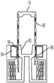
A drug delivery device usable with a drug container, wherein advancement of a piston within the container expels a drug. The device includes a housing and a drive assembly. The drive assembly includes a drive belt having a distal edge section and a proximal edge section. The drive belt has a retracted configuration defining a two-dimensional spiral and an extended configuration defining a three-dimensional spiral. The drive belt is movable from a retracted configuration to an extended configuration, wherein such movement defines a drive axis and advances the piston. In some embodiments, the drive belt may not rotate as it advances, while in other embodiments, the belt does rotate. The disclosed drive assembly includes a manually driven assembly, a spring driven assembly, and a motor driven assembly. The container may be replaceable to allow reuse of the device. In some embodiments, a replaceable cartridge that includes both a medicament container and a drive belt may be employed.
Description
Technical Field
The present disclosure relates to medical delivery devices, such as injection devices.
Background
Conventional injection devices are often used to inject a drug into a patient. For example, diabetics often use injection pens that utilize disposable cartridges containing insulin. Such pens typically include an elongate rod that acts on a piston within a cartridge. As the rod advances the piston, medication is dispensed through the needle into the patient.
Throughout the injection process, including when the rod has reached the limit of forward travel into the cartridge, the rod must protrude outwardly from the cartridge to engage the drive mechanism within the pen. When the rod has been fully retracted, it must also be contained within the pen so that the rod can be inserted into a new cartridge filled with medicine. As a result, conventional injection pens are generally elongated and slim, with the length of the injection pen being greater than twice the length of the cartridge tube in which the medication is contained. Similarly, for non-pen refillable injection devices, the length of the device is typically more than twice the length of the cartridge tube in which the drug is contained.
When such injection devices are used to self-administer medicine at different times throughout the day, it is desirable that the injection device is easily carried by the user. For example, diabetics often use injection devices to self-administer insulin and carry the device with them throughout the day. While conventional injection pens and similar devices are small enough to be portable, the length of such devices often makes the transportation of the devices inconvenient.
Disclosure of Invention
According to an embodiment of the present disclosure, a drug delivery device for use with a container having a container body containing a drug and defining an outlet is provided. The container includes a piston disposed within the container body, and advancement of the piston within the container body permits expulsion of the medicament through the outlet. The delivery device includes: a housing adapted to be coupled with a container; and a drive assembly coupled with the housing and adapted to advance the piston within the container. The drive assembly includes a drive belt having a distal edge section and a proximal edge section. The drive belt is incrementally movable about the drive axis between a retracted configuration and an extended configuration. In the retracted configuration the retracted portion of the drive belt defines a two-dimensional spiral (spiral), and in the extended configuration the extended portion of the drive belt defines a three-dimensional spiral (helix). The thrust member is engaged with the drive belt and is rotatable relative to the drive belt and the housing. In response to rotation of the thrust member, the drive belt is movable between a retracted configuration and an extended configuration without any rotation relative to the housing or container. Other embodiments of an exemplary apparatus are provided.
In another embodiment, a drug delivery device comprises a delivery device comprising: a housing adapted to be coupled with a container; and a drive assembly coupled with the housing and adapted to advance the piston within the container. The drive assembly includes a drive belt having a distal edge section and a proximal edge section. The drive belt has a retracted configuration and an extended configuration. The retracted portion of the drive belt defines a two-dimensional spiral in the retracted configuration, and the extended portion of the drive belt defines a three-dimensional spiral in the extended configuration. The drive belt is incrementally movable from a retracted configuration to an extended configuration. Movement of the drive belt from the retracted configuration to the extended configuration defines a drive axis. The drive mechanism is operably coupled with the drive belt and defines a secondary axis parallel to the drive axis. The drive mechanism generates a force that is transmitted to the drive belt to move the drive belt from the retracted configuration to the extended configuration.
In yet another embodiment, a drug delivery device comprises a delivery device comprising: a housing adapted to be coupled with a container; and a drive assembly coupled with the housing and adapted to advance the piston within the container. The drive assembly includes a drive belt having a distal edge section and a proximal edge section. The drive belt has a retracted configuration in which the retracted portion of the drive belt defines a two-dimensional spiral and an extended configuration in which the extended portion of the drive belt defines a three-dimensional spiral. A drive belt is incrementally movable from a retracted configuration to an extended configuration to advance the piston within the container body. Movement of the drive belt from the retracted configuration to the extended configuration defines a drive axis. One of the distal and proximal edge sections defines a plurality of edge projections, and the other of the distal and proximal edge sections defines a plurality of openings configured to receive the corresponding edge projections in an interlocking manner when the drive belt is in the extended configuration.
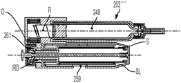
In yet another embodiment, a drug delivery device includes a drive module and a cassette. The drive module includes a module housing, a motor disposed within the module housing, and a drive gear operatively coupled to a shaft of the motor. The cartridge includes a cartridge housing configured to be coupled to the module housing. The cartridge includes: a container body containing a medicament and defining an outlet; and a piston disposed within the container body. A drive belt is incrementally axially extendable to advance the piston within the container body to expel the medicament through the outlet. The thrust member includes a driven gear element operatively coupled with the drive gear. The thrust member engages the drive belt and is movable to extend or retract the drive belt.
Drawings
The above-mentioned and other features of this disclosure and the manner of attaining them will become more apparent and the invention will be better understood by reference to the following description of embodiments of the disclosure taken in conjunction with the accompanying drawings, wherein:
FIG. 1 is a schematic perspective view of an exemplary drive belt that may be axially extended without rotation of the drive belt.
FIG. 2 is a schematic perspective view of another exemplary drive belt that rotates as it extends axially.
FIG. 3 is a schematic perspective view of another drive belt that rotates as it extends axially.
FIG. 4 is a partially exploded view of an exemplary drive belt.
Fig. 5 is a detailed view of the drive belt of fig. 4.
Fig. 6 is another detailed view of the drive belt of fig. 4.
FIG. 7 is a view of another drive belt, wherein the belt is deployed.
Fig. 8 is a detailed view of the drive belt of fig. 7.
FIG. 9 is an edge view of the drive belt of FIG. 7.
FIG. 10 is a schematic end view of an exemplary drive assembly having a drive belt that does not rotate as it extends.
Fig. 11 is another schematic view of the drive assembly of fig. 10.
FIG. 12 is a schematic end view of an exemplary drive belt that does not rotate as it extends.
FIG. 13 is a schematic side view of a drive assembly having the drive belt of FIG. 12.
FIG. 14 is a schematic end view of another drive assembly having a non-rotating drive belt.
FIG. 15 is a schematic side view of an exemplary drive assembly having the drive belt of FIG. 14.
FIG. 16 is a schematic end view of another drive assembly having a non-rotating drive belt.
Fig. 17 is a schematic side view of the drive assembly of fig. 16.
FIG. 18 is a schematic end view of a drive belt having elongated ribs.
FIG. 19 is a schematic end view of a drive belt having isolated columns.
Fig. 20 is a schematic side view of an exemplary drive assembly having a non-rotating drive belt.
FIG. 21 is a schematic side view of another drive assembly having a non-rotating drive belt.
Fig. 22 is a schematic end view of an exemplary drive assembly that includes a drive belt that rotates as it extends axially.
Fig. 23 is a schematic end view of another drive assembly including a drive belt that rotates as it extends axially.
Fig. 24 is a schematic side view of the drive assembly of fig. 23.
FIG. 25 is a schematic end view of a drive assembly having an internal gear drive for rotating a drive belt.
FIG. 26 is a schematic end view of another drive assembly having an internal gear drive for rotating a drive belt.
FIG. 27 is a schematic end view of a drive assembly having an external gear drive for rotating a drive belt.
FIG. 28 is a schematic end view of another drive assembly having an external gear drive for rotating the drive belt.
Fig. 29 is a schematic side view of the drive assembly of fig. 28.
Fig. 30 is a schematic end view of a drive assembly having an external belt drive.
FIG. 31 is a schematic end view of a drive assembly having a plurality of external gears for rotating a drive belt.
FIG. 32 is a schematic end view of another drive assembly having a plurality of external gears for rotating a drive belt.
Fig. 33 is a schematic side view of the drive assembly of fig. 32.
Figure 34 is a schematic end view of the outer worm gear drive.
Figure 35 is a schematic end view of another external worm gear drive.
FIG. 36 is a schematic end view of a drive belt having external ribs.
FIG. 37 is a schematic end view of a drive belt having an outer trough.
FIG. 38 is a schematic end view of a drive assembly having a drive belt with an external trough and a key drive.
Fig. 39 is a schematic side view of the drive assembly of fig. 38.
FIG. 40 is a schematic end view of another drive assembly having a drive belt with an external trough and a key drive.
Fig. 41 is a schematic side view of the drive assembly of fig. 40.
FIG. 42 is a schematic side view of the drive assembly with the retracted portion of the drive belt driven by the spool.
FIG. 43 is a schematic end view of a drive assembly having a reciprocating drive member.
FIG. 44 is a schematic perspective view of a drive assembly having a worm gear.
FIG. 45 is a schematic end view of a drive assembly having reciprocating drive members with a plurality of ratchet members.
Fig. 46 is a schematic diagram of an exemplary device having an inline drive assembly.
Fig. 47 is a side view of the device of fig. 46.
Fig. 48 is an end view of the device of fig. 47.
FIG. 49 is a schematic view of an exemplary device having a secondary axis.
Fig. 50 is a side view of the device of fig. 49.
Fig. 51 is an end view of the device of fig. 50.
FIG. 52 is a schematic view of another device having a secondary axis.
Fig. 53 is a side view of the device of fig. 52.
Fig. 54 is an end view of the device of fig. 53.
FIG. 55 is a schematic view of an exemplary device having a secondary axis.
Fig. 56 is a side view of the device of fig. 55.
Fig. 57 is an end view of the device of fig. 56.
Fig. 58 is an end view of the device of fig. 56.
Fig. 59 is a schematic view of the drive member mechanism of the device of fig. 55 in a dialled dose setting configuration.
Fig. 60 is a schematic view of the drive member mechanism of the device of fig. 55 in an injected dose delivery configuration.
FIG. 61 is a schematic view of an exemplary device having a secondary axis.
Fig. 62 is a side view of the device of fig. 61.
Fig. 63 is an end view of the device of fig. 62.
Fig. 64 is an end view of the device of fig. 62.
Fig. 65 is a schematic view of the drive member mechanism of the device of fig. 61 in a dialled dose setting configuration.
Fig. 66 is a schematic view of the drive member mechanism of the device of fig. 61 in an injected dose delivery configuration.
FIG. 67 is a schematic view of an exemplary device having a secondary axis.
Fig. 68 is a side view of the device of fig. 67.
Fig. 69 is an end view of the device of fig. 68.
Fig. 70 is an end view of the device of fig. 68.
Fig. 71 is a schematic view of the drive member mechanism of the device of fig. 67 in a dialled dose setting configuration.
Fig. 72 is a schematic view of the drive member mechanism of the device of fig. 67 in an injected dose delivery configuration.
FIG. 73 is a schematic view of an exemplary device having a secondary axis.
Fig. 74 is a side view of the device of fig. 73.
Fig. 75 is an end view of the device of fig. 74.
Fig. 76 is an end view of the device of fig. 74.
Fig. 77 is a schematic view of the drive member mechanism of the device of fig. 73 in a dialled dose setting configuration.
Fig. 78 is a schematic view of the drive member mechanism of the device of fig. 73 in an injected dose delivery configuration.
FIG. 79 is a schematic view of an exemplary device having a secondary axis.
Fig. 80 is a side view of the device of fig. 79.
Fig. 81 is an end view of the device of fig. 80.
Fig. 82 is an end view of the device of fig. 80.
Fig. 83 is a schematic view of the drive member mechanism of the device of fig. 79 in a dialled dose setting configuration.
Fig. 84 is a schematic view of the drive member mechanism of the device of fig. 79 in an injected dose delivery configuration.
FIG. 85 is a schematic view of an exemplary device having a secondary axis.
Fig. 86 is a side view of the device of fig. 85.
Fig. 87 is an end view of the device of fig. 86.
Fig. 88 is an end view of the device of fig. 86.
Fig. 89 is a schematic view of the drive member mechanism of the device of fig. 85 in a dialled dose setting configuration.
Fig. 90 is a schematic view of the drive member mechanism of the device of fig. 85 in an injected dose delivery configuration.
FIG. 91 is a schematic view of an exemplary device having a secondary axis.
Fig. 92 is a side view of the device of fig. 91.
Fig. 93 is an end view of the device of fig. 92.
Fig. 94 is an end view of the device of fig. 92.
Fig. 95 is a schematic view of a drive member mechanism of the device of fig. 91.
Fig. 96 is a schematic view of a drive member mechanism of the device of fig. 91.
Fig. 97 is a schematic view of an exemplary device having a secondary axis.
Fig. 98 is a side view of the device of fig. 97.
Fig. 99 is an end view of the device of fig. 98.
Fig. 100 is an end view of the device of fig. 98.
Fig. 101 is a schematic view of a drive member mechanism of the device of fig. 97.
Fig. 102 is a schematic view of a drive member mechanism of the device of fig. 97.
Fig. 103 is a schematic view of an apparatus with a detachable cartridge and drive module.
Fig. 104 is a side view of the device of fig. 103.
Fig. 105 is an end view of the device of fig. 104.
Fig. 106 is an end view of the device of fig. 104.
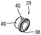
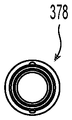
Fig. 107 is a side view of the cartridge of fig. 104.
Fig. 108 is a side view of the drive member mechanism module of fig. 104.
Fig. 109 is a schematic view of an exemplary device having a detachable cartridge and drive module.
Fig. 110 is a side view of the device of fig. 109.
Fig. 111 is an end view of the device of fig. 110.
Fig. 112 is an end view of the device of fig. 110.
Fig. 113 is a side view of the cartridge of fig. 110.
Fig. 114 is a side view of the drive member mechanism module of fig. 110.
Fig. 115 is a schematic diagram of an exemplary device with a detachable cartridge and drive module.
Fig. 116 is a side view of the device of fig. 115.
Fig. 117 is an end view of the device of fig. 116.
Fig. 118 is an end view of the device of fig. 116.
Fig. 119 is a side view of the cartridge of fig. 116.
Fig. 120 is a side view of the drive member mechanism module of fig. 116.
Fig. 121 is a schematic view of an exemplary apparatus with a detachable cartridge and drive module.
Fig. 122 is a side view of the device of fig. 121.
Fig. 123 is an end view of the device of fig. 122.
Fig. 124 is an end view of the device of fig. 122.
Fig. 125 is a side view of the cartridge of fig. 122.
Fig. 126 is a side view of the drive member mechanism module of fig. 122.
Fig. 127 is a schematic view of an exemplary apparatus with a detachable cartridge and drive module.
Fig. 128 is a side view of the device of fig. 127.
Fig. 129 is an end view of the device of fig. 128.
Fig. 130 is an end view of the device of fig. 128.
Fig. 131 is a side view of the cartridge of fig. 128.
Fig. 132 is a side view of the drive member mechanism module of fig. 128.
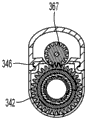
Fig. 133 is a schematic view of an exemplary drive member mechanism module with an attached cartridge and an additional cartridge.
Fig. 134 is a schematic view of the drive member mechanism module and plurality of cartridges of fig. 133.
Fig. 135 is a schematic view of an exemplary drive member mechanism module with an attached cartridge and an additional cartridge.
Fig. 136 is a schematic view of the drive member mechanism module and plurality of cartridges of fig. 135.
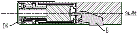
Fig. 137 is a side view of an exemplary device with a cartridge and modular drive member mechanism.
Fig. 138 is another side view of the device of fig. 137.
Fig. 139 is an end view of the device of fig. 138.
Fig. 140 is a cross-section taken along line a-a of fig. 137.
Fig. 141 is a cross-section taken along line B-B of fig. 140.
Fig. 142 is a cross-section taken along line C-C of fig. 140.
Fig. 143 is an exploded view of the device of fig. 137 showing the drive member mechanism and cartridge separated.
Fig. 144 is an exploded view of the device of fig. 137 showing a drive member mechanism and cartridge separated.
Fig. 145 is an exploded view of the device of fig. 137 showing the drive member mechanism and cartridge separated.
Fig. 146 is a side view of an exemplary device with a cartridge and modular drive member mechanism.
Fig. 147 is another side view of the device of fig. 146.
Fig. 148 is an end view of the device of fig. 147.
Fig. 149 is a cross-section taken along line a-a of fig. 146.
Fig. 150 is a cross-section taken along line B-B of fig. 149.
Fig. 151 is a cross-section taken along line C-C of fig. 149.
Fig. 152 is an exploded view of the device of fig. 146 showing a drive member mechanism and cartridge separated.
Fig. 153 is an exploded view of the device of fig. 146 showing the drive member mechanism and cartridge separated.
Fig. 154 is an exploded view of the device of fig. 146 showing the drive member mechanism and cartridge separated.
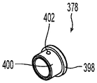
Fig. 155 is a perspective view of the cartridge.
Fig. 156 is a side view of the cartridge of fig. 155.
Fig. 157 is another side view of the cassette of fig. 155.
Fig. 158 is an end view of the cartridge of fig. 155.
Fig. 159 is a cross-section taken along line D-D of fig. 156.
Fig. 160 is a cross-section taken along line E-E of fig. 156.
Fig. 161 is a cross-section taken along line F-F of fig. 157.
Fig. 162 is a cross-section taken along line G-G of fig. 159.
Fig. 163 is a cross-section taken along line H-H of fig. 159.
Fig. 164 is an exploded perspective view of the cartridge.
Fig. 165 is a perspective view of the cartridge base of fig. 164.
FIG. 166 is a perspective view of the cartridge base of FIG. 164.
Fig. 167 is an end view of the cartridge base of fig. 164.
FIG. 168 is a side view of the cartridge base of FIG. 164.
FIG. 169 is an end view of the cartridge base of FIG. 164.
Fig. 170 is a side view of the cartridge base of fig. 164.
Fig. 171 is a perspective view of the cartridge collar of fig. 164.
Fig. 172 is a perspective view of the cartridge collar of fig. 164.
Fig. 173 is an end view of the cartridge collar of fig. 164.
Fig. 174 is a side view of the cartridge collar of fig. 164.
Fig. 175 is an end view of the cartridge collar of fig. 164.
Fig. 176 is a side view of the cartridge collar of fig. 164.
Fig. 177 is a perspective view of the cartridge ring of fig. 164.
Fig. 178 is a perspective view of the cartridge ring of fig. 164.
Fig. 179 is an end view of the cartridge ring of fig. 164.
Fig. 180 is a side view of the cartridge ring of fig. 164.
Fig. 181 is an end view of the cartridge ring of fig. 164.
FIG. 182 is a perspective view of the cassette foot of FIG. 164.
Fig. 183 is a perspective view of the cassette foot of fig. 164.
Figure 184 is an end view of the pod foot of figure 164.
FIG. 185 is a side view of the box foot of FIG. 164.
Figure 186 is an end view of the box foot of figure 164.
Fig. 187 is a perspective view of the cartridge nut of fig. 164.
Fig. 188 is a perspective view of the cartridge nut of fig. 164.
Fig. 189 is an end view of the cartridge nut of fig. 164.
Fig. 190 is a side view of the cartridge nut of fig. 164.
Fig. 191 is an end view of the cartridge nut of fig. 164.
FIG. 192 is a cross-section taken along line J-J of FIG. 190.
Fig. 193 is a perspective view of the cartridge holder of fig. 164.
Fig. 194 is a perspective view of the cartridge holder of fig. 164.
FIG. 195 is an end view of the cartridge holder of FIG. 164.
Fig. 196 is a side view of the cartridge holder of fig. 164.
Fig. 197 is an end view of the cartridge holder of fig. 164.
Fig. 198 is a perspective view of the cartridge holder of fig. 164.
FIG. 199 is a perspective view of the drive belt of FIG. 164.
FIG. 200 is a perspective view of the drive belt of FIG. 164.
FIG. 201 is a side view of the drive belt of FIG. 164.
FIG. 202 is an end view of the drive belt of FIG. 164.
Fig. 203 is a view of the outer surface of the drive belt of fig. 164 when laid flat.
Fig. 204 is a view of the drive belt of fig. 164 with the edges laid flat.
Fig. 205 is a view of the inner surface of the drive belt of fig. 164 as laid flat.
Figure 206 is an enlarged view of the section of the drive belt shown in detail J of figure 203.
Figure 207 is an enlarged view of the section of the drive belt shown in detail K of figure 205.
Fig. 208 is a view of the outer surfaces of the two drive belts of fig. 164 coupled together and laid flat for explanatory purposes.
Fig. 209 is a view of the inner surfaces of the two drive belts of fig. 164 coupled together and laid flat for explanatory purposes.
Figure 210 is an enlarged view of the section of the drive belt shown in detail L of figure 208.
Figure 211 is an enlarged view of the section of the drive belt shown in detail M of figure 209.
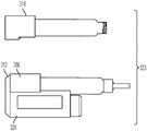
Fig. 212 is a schematic diagram of a control system for controlling the amount of dose delivered by the device.
Figure 213 is a schematic diagram of another control system for controlling the amount of dose delivered by the device.
Fig. 214 is a schematic top view of the control system of fig. 213.
Fig. 215 is a schematic diagram of another control system for controlling the amount of dose delivered by the device.
FIG. 216 is a schematic diagram of an alternative physical layout of the control system.
Corresponding reference characters indicate corresponding parts throughout the several views. While the exemplification set out herein illustrates embodiments of the disclosure in several forms, the embodiments disclosed below are not intended to be exhaustive or to be construed as limiting the scope of the invention to the precise forms disclosed.
Detailed Description
An example of a drug delivery device is provided. One of the advantages may be that such a delivery device may provide a configuration having a relatively short length and a compact configuration. In some embodiments, the device is a disposable device (such as an auto-injector) having a syringe prefilled with a drug, such as, for example, insulin or other types of medicaments used to treat diabetes. In some embodiments, the device includes a disposable syringe cartridge that is removably coupled to the drive housing such that a patient can replace a used cartridge with another cartridge having a new and/or different medication. The drive housing may include electronics for sensing, indicating, displaying, and/or communicating on-board and/or off-board steps in the delivery of the medicament.
The illustrated device utilizes an axially expandable drive belt as part of a drive assembly for dispensing the medicament. As can be seen with reference to fig. 1-3, the drive belt of the exemplary embodiment has a retracted configuration in which the retracted portion of the drive belt 22 defines a two-dimensional spiral, and an extended configuration in which the extended portion of the drive belt 24 defines a three-dimensional spiral.
As used herein, the retracted portion 22 of the drive belt defines a proximal end and the opposite end of the extended portion 24 of the drive belt defines a distal end. The drive belt may be incrementally displaced between a retracted configuration and an extended configuration to alter the length of the extension portion 24. The band is formed into a three-dimensional spiral when the drive band is displaced to the extended configuration, and the band is secured to itself when the proximal edge region of the band engages the distal edge region of the band.
Fig. 1 to 3 illustrate several different ways in which the drive belt can function. Fig. 1 schematically depicts a drive belt 26, wherein the extension portion 24 of the drive belt is advanced without rotation of the extension portion 24. In such embodiments, as the extended portion of the drive belt is axially advanced, the most recently retracted portion of the belt is stretched radially inward and upward such that the distal edge of the belt being pulled engages the proximal edge of the belt at the bottom of the extended portion of the belt. The band may be guided in this motion by using a cam ramp that engages the proximal edge of the band that is stretched radially inward and upward.
One advantage of such a non-rotating drive belt is that the support member attached to the distal end of the belt will not rotate and can therefore be directly supported on the piston of the medicament container without any relative rotational movement between the support member and the piston.
Fig. 2 and 3 schematically depict drive belts 28, 30, which rotate as they extend axially. The difference between the drive belt 28 shown in fig. 2 and the drive belt 30 shown in fig. 3 is the manner in which the distal and proximal edges of these belts engage. The edges of the band 28 shown in fig. 2 project inwardly and outwardly to form a projecting lip. Similar straps are shown in fig. 7-9 and 33 discussed below.
Similar to the belt 26, the drive belt 30 is formed into a more cylindrical shape, and the proximal and distal edges of the belt do not protrude or form significant discontinuities in the inner and outer surfaces of the extended portion 24 of the belt. The drive belts shown in fig. 4-6 and 11 have this type of engagement and are discussed further below.
The use of a rotating drive belt allows for a greater variety of drive belt configurations than a non-rotating drive belt. However, rotation of the drive belt will generally require mounting the support member to a secondary part on the drive belt to allow the support member engaged with the piston of the medicament container to rotate relative to the drive belt. This will allow the support member to engage the piston of the medicament container without any relative movement between the support member and the piston. This arrangement may also increase the overall length of the drive belt assembly.
The use of such a drive belt allows an injection device or similar drug delivery device to have a relatively short and compact size due to the short axial length of the retracted portion of the drive belt. Various drive assemblies for moving drive belts and apparatus architectures are disclosed herein and discussed below.
Exemplary drive Belt
One example of a drive belt 32, which forms a generally cylindrical extension (similar to the belts of fig. 1 and 3), is shown in fig. 4-6. The strap 32 will not assume the shape shown in fig. 4 during use, and is shown in this configuration merely to assist in the structure of the strap 32. A foot member 34 is secured to the distal end of the strap 32. If the band 32 is used in a non-rotating application, the feet 34 may bear directly against the piston of the drug container. The foot 34 also includes a central aperture that may act as a rotatable support. For example, a support member having a protrusion that fits into a central hole of the foot 34 may be rotatably mounted on the foot 34 and directly supported on the piston instead of the foot 34. Such an arrangement would facilitate the use of the belt 32 in applications where the drive belt is rotated as it is axially advanced.
The band 32 has a distal edge section 36 and a proximal edge section 38 which are engageable with one another and are shown in more detail in fig. 5 and 6. The distal edge section 36 faces inwardly and includes a recess 40 disposed between an inwardly projecting lip 42 and an inwardly projecting ledge 44. The lip 42 also includes a series of notches 46. The inwardly facing surface of the band 32 also includes a series of raised ribs 48. The ribs 48 may be engaged by a gear or similar drive member mechanism to rotatably drive the movement of the belt 32.
The proximal edge section 38 can be seen in fig. 6, and the outwardly facing surface of the band 32 includes a lip 50 and a recess 52 along the proximal edge of the band 32. An axially extending rib 54 is located within the recess 52. When the proximal and distal sections of the band 32 are joined together, the lip 50 fits within the recess 40, with the lip 42 and the boss 44 constraining axial movement of the lip 50. Similarly, the lip 42 fits within the recess 52 and is therefore axially constrained. This axial engagement allows the extension of the band 32 to exert an axial compressive force (such as when the piston is biased forward to expel the drug) and to resist an axial tensile force to thereby prevent the extension of the band from becoming disengaged from itself as a result of being pulled axially apart. The ribs 54 cooperate within the notches 46 to provide shear resistance and to allow the extended portion of the belt to withstand the torque that the belt may experience when rotating.
An example of a drive belt having proximal and distal edges that form a protruding lip when engaged (similar to the belt of fig. 2) and having a sidewall that assumes a slightly conical shape when in an extended position is shown in fig. 7-9. In fig. 7, the tape 56 is shown laid on a flat surface. Fig. 8 and 9 provide more detailed views of the belt 56.
A plurality of pegs 60 are located in the recesses 58 and engage a corresponding plurality of holes 62. In the illustrated embodiment, the peg 60 is located on the proximal edge section with the hole 62 located on the distal edge section. However, in other examples, these positions may be reversed. When the drive band 56 is extended and formed into a three-dimensional spiral, the engagement of the proximal edge section with the adjacent portion of the distal edge section includes the engagement of the peg 60 with the aperture 62. In the illustrated embodiment, the peg 60 has a chamfered tip surface that facilitates entry and removal of the peg 60 from the hole 62.
The engagement of the peg 60 with the aperture 62 axially secures adjacent portions of the drive belt 56 together. The engagement of the peg 60 and the hole 62 also provides for the transmission of torque between adjacent portions of the extended band and maintains stability of the column formed by the extended band.
In the illustrated embodiment, the drive belt 56 has a plurality of recesses 64 that provide a geared surface. The recess 64 is engaged by a gear member or other suitable drive member whereby the drive assembly can rotate the drive belt 56 by transmitting a rotational force to the drive belt 56. As can be seen in fig. 7, the drive belt 56 includes a tapered section 66 that defines the distal end of the drive belt when formed into a three-dimensional spiral and has a support member (such as the foot 34) mounted thereto.
The illustrated drive belt utilizes a flexible polymeric belt that has been machined to define various features of the belt. Nylon, polypropylene, acetal (polyoxymethylene or POM), and high density polyethylene are examples of suitable polymeric materials that may be used to form the drive belt. While the illustrated embodiment is machined, alternative embodiments may use a molding process to form a polymeric tape having all of its features. It is envisioned that molding the tape in a flat arrangement and then rolling the tape into a two-dimensional spiral configuration would be the most efficient manufacturing method of forming the tape.
Other materials may also be used to form the drive belt. For example, a thin metal strip may be used to form the belt. Photolithography, laser etching, or other suitable micromachining methods may be used to form the various features of the ribbon. Alternatively, instead of using a single metal strip, the metal strip may be formed by diffusion bonding two half-thickness layers.
Still other belt embodiments may take the form of an overmolded metal strip. The metal strip will be provided with distal edge features and the overmolded plastic portion of the band will form the various features of the band. This approach combines the desired hardness, resiliency and creep resistance of metal with low friction and ease of manufacture to form small features in molded plastic. It will generally be desirable for the band to be flexible so that it can be extended and retracted and withstand the attendant elastic stresses without permanent deformation.
In this regard, it should be noted that the various embodiments disclosed herein may be either single use devices or multiple use devices, some of which are best suited for one use or the other. The multi-use device will have a drive belt that can be extended and retracted multiple times so that the device can be reused with a new drug container after the drug container is depleted. A single use drive belt would be used with only a single drug container and, once extended, would be discarded. Such single use drive belts need not have the ability to retract after extension. The ability of the drive belt to resist axial tension during retraction of the drive belt and in the event that the drive belt is exposed when extended, and therefore to resist axial separation in the extended portion of the drive belt, is of paramount importance. This concern is reduced, if not eliminated, for single use drive belts, and for at least some applications, the extended portion of the drive belt need not have the ability to resist axial separation forces.
Non-rotating drive belt
Fig. 10 to 21 relate to a device with a drive belt which does not rotate when it is axially advanced. Such a drug delivery device is suitable for use with a container having a container body containing a drug and defining an outlet, wherein the container comprises a piston disposed within the container body and advancement of the piston within the container body expels the drug through the outlet (e.g., a hollow needle). The delivery device includes: a housing adapted to be coupled with a container; and a drive assembly coupled with the housing and adapted to advance the piston within the container. The drive assembly includes a drive belt having a distal edge section and a proximal edge section. The drive belt has a retracted configuration in which the retracted portion of the drive belt defines a two-dimensional spiral and an extended configuration in which the extended portion of the drive belt defines a three-dimensional spiral. The drive belt is incrementally movable from a retracted configuration to an extended configuration. Movement of the drive belt from the retracted configuration to the extended configuration defines a drive axis and advances the piston within the container body. The drive belt moves from the retracted configuration to the extended configuration without rotating relative to the housing or container. The thrust member engages the drive belt. The thrust member is rotatable relative to both the drive belt and the housing. Rotation of the thrust member moves the drive belt from the retracted configuration to the extended configuration.
Non-rotating drive belt with stationary thrust member
In some embodiments with such non-rotating drive belts, the thrust member is axially stationary. Such an axially stationary thrust member may comprise a three-dimensional helical thread engageable with the drive belt, and the device may further comprise a rotation restricting member, wherein the rotation restricting member is rotationally fixed relative to the housing and engages with the drive belt, and wherein engagement of the drive belt and the rotation restricting member prevents relative rotation of the extension of the drive belt and the rotation restricting member.
In such an arrangement having a rotation-restricting member, one of the rotation-restricting member and the extension portion of the drive belt may define an axially-extending key, wherein the other of the rotation-restricting member and the extension portion of the drive belt defines an axially-extending keyway.
The rotation restricting member may be disposed radially outward of the drive belt at an engagement position where the rotation restricting member engages the drive belt to prevent rotation. See, for example, the embodiments of fig. 10 and 11, the embodiments of fig. 12 and 13, and the embodiments of fig. 16 and 17.
Alternatively, the rotation restricting member may be provided radially inside the drive belt at a position where the rotation restricting member engages the drive belt to prevent rotation. See, for example, the embodiment of fig. 14 and 15.
For embodiments having an axially stationary thrust member with a three-dimensional helical thread, the three-dimensional helical thread may be disposed radially outward of the drive belt at a location where the three-dimensional helical thread engages the drive belt. See, for example, the embodiment of fig. 10 and 11, the embodiment of fig. 12 and 13, and the embodiment of fig. 14 and 15. Alternatively, the three-dimensional helical thread may be disposed radially inward of the drive belt at a location where the three-dimensional helical thread engages the drive belt. See, for example, the embodiment of fig. 16 and 17.
Turning now to the embodiment of fig. 10 and 11, this embodiment includes a rotation restricting member 68 disposed radially outward of a drive belt 70. The projection 72 on the rotation restricting member 68 engages an axially extending slot 73 defined in the extension of the drive belt 70 to define an engagement position 75. The restraining member 68 is fixed relative to the housing and the housing may also support the medicament container without relative movement between the housing and the container. Thus, the projection 72 prevents rotation of the extended portion of the drive belt 70 relative to the housing and the medicament container. As a result, the support member or foot 74 may be secured to the drive belt 70.
The thrust member 76 includes at least one three-dimensional helical thread 78 that engages a groove 80 forming a three-dimensional helical shape on the extension of the drive belt 70. As the thrust member 76 and the threads 78 rotate, they pull and guide the drive belt 70 from its retracted configuration 69 into its extended configuration 71. The threads 78 also exert an axial force on the band 70 whereby the band 70 can exert a biasing force on the medicament container piston via the feet 74 to dispense medicament.
A drive gear or other suitable drive member engages thrust member 76, such as on an outer radial surface 76A of thrust member 76, to drivingly rotate thrust member 76. For example, the outer radial surface 76A may be a geared surface that engages a motor-driven gear to thereby rotate the thrust member 76.
The embodiment of fig. 12 and 13 has the same general structure as the embodiment of fig. 10 and 11. The embodiment of fig. 12 and 13 differs, however, in that the drive belt 82 has an outwardly extending projection or post 84 that engages an axially extending slot in the rotation-restricting member 86 to prevent rotation of the drive belt 82. The use of the projections 84 avoids the use of axially aligned grooves on the drive belt, which may be difficult to form using a roll forming process.
The embodiment of fig. 14 and 15 has a drive belt 88 having a groove on its outer surface that takes the form of a three-dimensional spiral over the extension of the drive belt 88. The band 88 also has grooves on its inner surface that extend axially in the extension of the band.
The rotation-restricting member 90 is disposed radially inward of the drive belt 88 and includes axially extending ribs 92 that engage grooves on the inner surface of the belt 88 to define engagement locations 93 to prevent rotation of the extended portion of the drive belt 88.
An axially stationary thrust member 94 is disposed radially outwardly of the drive belt 88 and includes a three-dimensional helical thread 96 that engages a groove on the outer surface of the belt 88 that takes the shape of a three-dimensional helix on the extension of the rib 88. As the thrust member 94 rotates, it pulls the belt 88 from its retracted configuration into its extended configuration and may exert an axial force on the drive belt 88.
The embodiment of fig. 16 and 17 has a drive belt 98 with an inner groove 99 defining a three-dimensional helical shape in the extension of the drive belt and an outer groove extending axially in the extension of the drive belt.
The rotation-inhibiting member 100 is disposed radially outward of the band 98 and includes ribs 102 that engage axially-extending external grooves on the band 98 to define an engagement position to prevent rotation of the band 98. An axially stationary thrust member 104 is rotatably mounted on the shaft and includes a three-dimensional helical thread 106. The thrust member 104 and threads 106 rotate and pull the band 98 into the extended configuration as they rotate. The threads 106 also exert an axial force on the band 98.
Fig. 18 and 19 schematically depict two drive belts 108, 82 that include radially outwardly extending projections that engage slots in the rotation-restricting member to prevent rotation of the belts. Drive belt 82 includes a plurality of outwardly extending projections 84 that are both axially and circumferentially spaced apart, as can also be seen in fig. 12 and 13. The drive belt 108 of fig. 18 has elongate ribs 110 which are circumferentially spaced apart but which are substantially continuous in the axial direction for the extension of the drive belt.
Non-rotating drive belt with axially movable thrust member
In some embodiments having a non-rotating drive belt, the thrust member moves axially in the proximal direction P as it rotates, and the distal end of the drive belt remains axially stationary as the thrust member rotates. To advance the piston within the container body, the thrust member and the extension portion of the drive belt are moved axially in a distal direction D opposite the proximal direction. Examples of such devices are shown in fig. 20 and 21. Throughout this disclosure, the orientation using the proximal and distal sides is consistent.
The apparatus may also include a drive spring that is tensioned when the thrust member is rotated to extend the drive belt. As the band extends, the thrust member moves axially in the proximal direction and the distal end of the drive band remains stationary. To initiate dispensing of the medicament, the thrust member and drive spring are released and the drive spring axially advances the thrust member with the extension of the drive belt. The drive belt thereby advances the piston in the medicament container to dispense the medicament.
The embodiment of fig. 20 has an axially movable thrust member 112, the thrust member 112 comprising a three-dimensional helical thread 114 engageable with a drive belt 124, wherein the three-dimensional helical thread 114 is disposed radially inward of the drive belt 124 at the location where the three-dimensional helical thread engages the drive belt. The rotation restricting member 122 is rotationally fixed relative to the housing and engages the drive belt 124 such that engagement of the drive belt and the rotation restricting member prevents relative rotation of the extension of the drive belt 124 and the rotation restricting member 122.
The threads 114 of the thrust member 112 engage three-dimensional helical grooves on the inward facing surface of the drive belt 124. Thrust member 112 has a hollow center defining a central bore for receiving central shaft 118. Thrust member 112 has a three-dimensional helical thread 116 facing its central bore that engages a three-dimensional helical groove on shaft 118. As thrust member 112 rotates to move proximally on shaft 118, it compresses drive spring 120. FIG. 20 shows the thrust member in its proximal-most position.
The shaft 118 may extend further proximally of the drive assembly than shown in fig. 20 and engage a locking mechanism that prevents axial movement of the shaft 118. After rotating thrust member 112 to move it in a proximal direction and compress spring 120, shaft 118 may be released, thereby also releasing thrust member 112 and spring 120. Spring 120 will then bias thrust member 112 distally, and threads 114 on thrust member 112 will cause drive spring 120 to advance distally with thrust member 112.
The embodiment of fig. 21 comprises an axially movable thrust member 126 comprising a three-dimensional helical thread 128 engageable with a drive belt 130, wherein the three-dimensional helical thread 128 is disposed radially outward of the drive belt 130 at the location where the three-dimensional helical thread engages the drive belt. The rotation restricting member 132 is rotationally fixed relative to the housing and engages the drive belt 130 such that engagement of the drive belt 130 and the rotation restricting member 132 prevents relative rotation of the extension portion of the drive belt 130 and the rotation restricting member 132.
The thrust member 126 may extend radially outward to a greater extent than shown in fig. 21 such that it releasably threadably engages the housing. When the thrust member 126 is rotated relative to the housing, it will move in the proximal direction and compress the drive spring 134. Reference numeral 127 is used in fig. 21 to identify the position of the thrust member 126 after it has been rotated to retract it proximally. After retracting the thrust member 126, the thrust member may be released, which will also release the drive spring 134, whereby the spring 134 will axially advance the thrust member 126 in the distal direction. The threads 128 on the thrust member 126 will cause the drive belt 130 to advance axially in the distal direction with the thrust member 126 and thereby advance the medicament container piston to dispense medicament.
Rotatable drive belt
Fig. 22 to 45 relate to the drive belt which rotates as it advances axially. Such a band may be employed in a drug delivery device for use with a container having a container body containing a drug and defining an outlet, wherein the container comprises a piston disposed within the container body and advancement of the piston within the container body expels the drug through the outlet. The delivery device includes: a housing adapted to be coupled with a container; and a drive assembly coupled with the housing and adapted to advance the piston within the container. The drive assembly includes a drive belt having a distal edge section and a proximal edge section. The drive belt has a retracted configuration in which the retracted portion of the drive belt defines a two-dimensional spiral and an extended configuration in which the extended portion of the drive belt defines a three-dimensional spiral. The drive belt is incrementally movable from a retracted configuration to an extended configuration, and movement of the drive belt from the retracted configuration to the extended configuration defines a drive axis. The drive belt rotates as it moves from the retracted configuration to the extended configuration.
Fig. 22 to 24 relate to an apparatus in which a drive member is provided on a radially inner side of a drive belt to engage and rotate the drive belt, and a fixing part having a three-dimensional helical thread is provided on a radially outer side of the drive belt. The three-dimensional helical thread of the fixed member engages the drive belt and controls movement of the drive belt between the retracted configuration and the extended configuration.
Fig. 22 illustrates an assembly in which the drive member 136 has a pair of keys 138 that engage grooves on the inward facing surface of a drive belt 140 to drivingly rotate the belt 140. The collar 142 is fixed relative to the housing and includes a three-dimensional helical thread 144 that engages a three-dimensional helical groove on the outward facing surface of the drive belt 140.
Fig. 23 and 24 illustrate an assembly very similar to that shown in fig. 22, but in which the drive member 146 has a greater number of keys 148 to engage a correspondingly greater number of grooves on the inner surface of the drive belt 150 to define the engagement position.
Because the drive belt 150 rotates as it is axially advanced, a rotatable bearing assembly 152 is employed having a first member 154 fixed to the drive belt 150 and a second member 156 rotatable relative to the member 154 and the belt 150. The second member 156 may bear directly against the piston of the medicament container without rotating relative to the piston, while the first member 154 and the band 150 both rotate relative to the member 156 and the piston as the band advances and biases the member 156 against the piston to advance the piston.
Fig. 25 and 26 illustrate alternative drive arrangements that are provided radially within the drive belt to engage and rotate the drive belt. Fig. 25 illustrates the use of a single gear member 158, while fig. 26 illustrates the use of multiple gears 160. The gears 158, 160 will engage axially extending grooves or raised ribs (not shown) on the inner surface of the drive belt. Such grooves/ribs will be spaced apart a distance corresponding to the distance between gear teeth on the gear with which the belt is used.
Fig. 27 to 41 relate to embodiments having a rotatable drive belt, wherein a drive member disposed radially outward of the drive belt engages and drivingly rotates the drive belt.
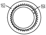
Fig. 27 schematically depicts the use of a single ring gear 162 with a drive belt 164. The ring gear 162 completely surrounds the drive belt 164 and engages a portion of the outer surface of the drive belt 164. The central opening of the ring gear 162 is larger than the outer diameter of the drive belt 164, and therefore, a portion of the outer circumference of the drive belt is not engaged by the ring gear 162. Fig. 28 and 29 schematically depict the use of multiple ring gears. In the illustrated embodiment, two ring gears 166 engage the drive belt 164. The use of two ring gears 166 allows the full outer circumference of the drive belt 164 to be engaged by the ring gears. As can be seen in fig. 29, the ring gear 166 is axially offset. The arrangement of fig. 29 also includes a main shaft member 168 having a three-dimensional helical thread 170 that engages a groove on the inner surface of the drive belt 164. The ring gear 166 is advantageously positioned axially such that the ring gear 166 engages the outer surface of the drive belt proximate where the threads 170 engage the inner surface of the drive belt.
Various other types of drive members may alternatively be employed to drivingly rotate the drive belt. Fig. 30 schematically depicts the use of a belt drive arrangement in which a belt 172 engages an outer surface of a drive belt 174 to rotate the drive belt. A driven shaft 176 or other suitable mechanism drives the belt 172.
Multiple planetary gears may also be employed to rotate the drive belt. Fig. 31 depicts the use of planet gears 178, which are also reduction gears, while fig. 32 and 33 depict a slightly different embodiment in which the planet gears 180 are not reduction gears. As can be seen in fig. 33, the three-dimensional helical thread 182 engages the inwardly projecting proximal edge of the drive belt 184, while the planet gear 180 engages the outer surface of the drive belt 184. Similar to the drive belt of fig. 7-9, the drive belt 184 has outwardly projecting edges at which it engages itself.
Fig. 34 and 35 depict an alternative drive arrangement that employs a worm gear to rotate a drive belt. In fig. 34, a pair of worm gears 186 engage the outer surface of a drive belt 188 to rotate the belt 188. Fig. 35 depicts a drive arrangement in which a single worm gear 190 is used to rotate drive belt 188. While the use of a single worm gear will reduce the complexity and number of parts compared to the use of two worm gears, the use of a pair of worm gears disposed on opposite sides of the drive belt provides a more balanced force distribution on the drive belt.
Fig. 36 to 41 relate to the use of a key drive to drivingly rotate the drive belt. Fig. 36 depicts drive belt 192 having a plurality of keys or ribs 194 that extend axially when drive belt 192 is in an extended configuration. The ribs 194 may be engaged by keyways or grooves on the drive member to drivingly rotate the belt 192. Fig. 37 depicts a drive belt 196 having a plurality of keyways or grooves 198 that extend axially when the drive belt 196 is in an extended configuration. The slot 198 may be engaged by a key or similar protrusion on the drive member to drivingly rotate the belt 196.
Fig. 38 and 39 depict examples of key drive arrangements. In fig. 38 and 39, the drive member 200 has a plurality of ribs or keys 202 that engage axially extending grooves on the outer surface of the drive belt 204. As the drive member 200 rotates, the drive belt 204 also rotates. The stationary main shaft member 206 has a three-dimensional helical thread 208 that engages a groove on the inner surface of the drive belt 204.
Fig. 40 and 41 depict another example of a key drive arrangement. In this arrangement, the drive member 210 includes a plurality of ribs or keys 212 that engage axially extending grooves on the outer surface of the drive belt 214 to drivingly rotate the belt 214. The stationary collar member 216 includes a three-dimensional helical thread 218 that engages a groove on the outer surface of the drive belt 214.
The non-engaging portion of the drive belt being engaged by the drive member
Fig. 42-45 relate to a drug delivery device for use with a container having a container body containing a drug and defining an outlet. The container includes a piston disposed within the container body, wherein advancement of the piston within the container body expels the medicament through the outlet. The delivery device includes: a housing adapted to be coupled with a container; and a drive assembly coupled with the housing and adapted to advance the piston within the container. The drive assembly includes a drive belt having a distal edge section and a proximal edge section. The drive belt has a retracted configuration in which the retracted portion of the drive belt defines a two-dimensional spiral and an extended configuration in which the extended portion of the drive belt defines a three-dimensional spiral. The drive belt is incrementally movable from a retracted configuration to an extended configuration. Movement of the drive belt from the retracted configuration to the extended configuration defines a drive axis and advances the piston within the container body. The drive belt rotates as it moves from the retracted configuration to the extended configuration. The drive belt further defines a transition portion disposed between the retraction portion and the extension portion, wherein the distal edge section and the proximal edge section of the drive belt are not joined together in the transition portion. The drive member engages and drivingly rotates the drive belt, and the drive member engages a retraction portion or transition portion of the drive belt.
Storage spool drive member
Fig. 42 depicts an arrangement including a storage spool 220 housing a retracted portion of a drive belt 222. The portion of the drive belt 222 disposed within the storage spool 220 expands radially outward to engage the storage spool 220. Thus, as the storage spool 220 rotates, the drive belt 222 also rotates. This may be used to force the drive belt 222 into engagement with the collar member 224. The collar member 224 includes a three-dimensional helical thread 226 that engages a groove on the outer surface of the drive belt 222 to control and guide the belt 222 into engagement with itself to thereby axially extend the belt 222. It should be noted that rotation of spool 220 in the opposite direction may be used to retract band 222. Similarly, for nearly all drive member mechanisms disclosed herein, unless specifically stated otherwise, the drive member mechanism can be operated in reverse to retract and extend the drive belt.
Reciprocating drive member
Fig. 43 illustrates a reciprocating drive member 228 engaging a drive belt 230 in a transition portion 231 of the drive belt (between the retracted portion and the extended portion). As can be seen in fig. 43, the reciprocating drive member 228 engages a radially inward facing surface of the drive belt 230. For some embodiments of the drive member 228, the cyclical motion of the member 228 and its engaging nature will result in the member 228 being able to drive the belt 230 into its extended position, but not being able to drive the belt 230 into its retracted position.
Worm wheel
Fig. 44 depicts an embodiment in which the worm gear 232 engages the drive belt 234 in the retracted portion of the drive belt.
Reciprocating ratchet drive
Referring now to fig. 45, for embodiments having a reciprocating drive member, the reciprocating drive member 236 may take the form of a drive member that moves in a first direction and an opposite second direction (as depicted by double arrow 242). Drive member 236 is shown to include at least one flexible ratchet member 244 engageable with drive belt 238, the flexible ratchet member being configured to allow relative movement between drive member 236 and drive belt 238 in a first direction 243 and not allow relative movement (or allow unidirectional movement) between drive member 236 and drive belt 238 in a second direction 241. When moving in the second direction 241, the drive member 236 will push the drive belt and thereby cause the drive belt 238 to move. When moving in the first direction 243, the ratchet member 236 will be repositioned on the drive belt 238, whereby it can push the belt forward when moving again in the second direction 241. The illustrated embodiment also includes a stationary ratchet member 240 that does not move relative to the housing and includes a plurality of ratchet members 244 that engage the radially outward facing surface of the drive belt 238. When the reciprocating drive member 236 moves in the first direction 243, the ratchet member 240 will ensure that the drive belt 238 is not pulled back by the reciprocating ratchet member 236. The ratchet drive depicted in FIG. 45 is well suited for use in a single use device, where the strap is extended but not subsequently retracted. If it is desired to use such a ratchet drive in a multi-use device, the ratchet members 236 and 240 would have to be movable off of the drive belt and a second drive mechanism employed to rotate the drive belt in the opposite direction. To generate the reciprocating motion of the drive member 236 and the drive member 228 discussed above, an oscillating escapement drive can be employed.
Device architecture
The various bands and drive member mechanisms disclosed herein may be combined in many ways to provide a drug delivery device. Two general classes of such devices include devices having an in-line architecture and devices having a two-axis architecture. These two basic architectures are depicted in fig. 46-54.
In-line architecture
Devices having an in-line architecture are depicted in fig. 46-48. In this arrangement, both the drive belt R and the extended drive member mechanism for driving the drive belt share a common axis 246. As shown in fig. 46, the apparatus includes: a dial knob DK for setting the dose; and an injection button B which initiates extension of the drive belt. The device also houses a medicament container 248. The illustrated container 248 is a conventional syringe cartridge having a glass tube containing the medicament, a piston 250 disposed within the tube, and an outlet defined by a hollow injection needle 252. When drive band R is extended, a bearing member 254 disposed on the distal end of band R bears against piston 250 to advance piston 250 within reservoir 248 and thereby expel the drug through needle 252.
Two-axis architecture
Fig. 49-54 provide simplified depictions of dual axis devices. Fig. 55-132 provide more detailed schematic images of the dual axis device, and the figures following fig. 132 provide even further representations of the dual axis device. Throughout the drawings, reference to common components (such as the needle 252, the reservoir 248, the dial knob DK, the drive belt R and the injection button B) will be used for different device configurations. As will become apparent from the discussion below, the dual axis arrangement includes a primary drive axis defined by the drive belt, and further includes a drive member mechanism defining a secondary axis parallel to and offset from the primary drive axis. One advantage of the dual axis arrangement is that by offsetting a portion of the drive member mechanism from the main axis, the drive member mechanism can be positioned to extend parallel to the main axis in the distal direction. This allows for an overall shorter length of such a two-axis arrangement relative to a situation where the entire drive member mechanism is positioned in alignment with the main axis.
As can be seen in fig. 49-54, the dual-axis architecture can increase the volume of the device (referred to herein as 253) over a relatively short length portion of the device, which can be beneficial to patient users who have dexterity or treatment challenges due to debilitating diseases or conditions. The device 253 depicted in fig. 49-51 is for dispensing medicament from a conventional 3 ml syringe cartridge and has a drive belt defining a first major axis 254 and a drive member mechanism defining a secondary parallel axis 256. Similarly, the device depicted in fig. 52-54 (referred to herein as 253') also dispenses medicament from a conventional 3 ml syringe cartridge and has a drive belt defining a first major axis 254 and a drive member mechanism defining a secondary parallel axis 256. The housings of the two components (cartridge/drive belt portion and drive member mechanism component portion) may have different housing configurations.
Both these devices, and the devices depicted in fig. 55-132, are drug delivery devices for use with a container having a container body containing a drug and defining an outlet. The container includes a piston disposed within the container body, wherein advancement of the piston within the container body expels the medicament through the outlet. The delivery device includes: a housing adapted to be coupled with a container; and a drive assembly coupled with the housing and adapted to advance the piston within the container. The drive assembly includes a drive belt having a distal edge section and a proximal edge section. The drive belt has a retracted configuration in which the retracted portion of the drive belt defines a two-dimensional spiral and an extended configuration in which the extended portion of the drive belt defines a three-dimensional spiral. The drive belt is incrementally movable from a retracted configuration to an extended configuration. Movement of the drive belt from the retracted configuration to the extended configuration defines a drive axis and advances the piston within the container body. The drive member mechanism is operably coupled with the drive belt and defines a secondary axis parallel to the drive axis. The drive member mechanism generates a force that is transmitted to the drive belt to move the drive belt from the retracted configuration to the extended configuration.
Several embodiments of such a two-axis device will now be discussed. Various embodiments include several illustrated examples, such as those depicted in fig. 55-78 and 97-114, having a drive member mechanism including a spring S aligned with a secondary axis, wherein setting a dose includes tensioning and releasing tension from the spring S to generate a force that is transferred to a drive belt R to move the drive belt from a retracted configuration to an extended configuration.
Several of the illustrated dual-axis embodiments (such as those depicted in fig. 79-96) have a drive member mechanism that includes a plunger disposed along a secondary axis, wherein linear translation of the plunger generates a force that is transmitted to the drive belt R to move the drive belt from the retracted configuration to the extended configuration.
Still others of the illustrated dual-axis embodiments (such as those depicted in fig. 115-132) have a drive member mechanism that includes an electric motor M drivingly coupled with elements disposed along a secondary axis, the electric motor M generating a force that is transmitted to a drive belt R to move the drive belt from a retracted configuration to an extended configuration. In such an embodiment, the element disposed along the secondary axis may be a drive shaft of an electric motor.
In some of the illustrated embodiments, such as the embodiment of fig. 55-102, the drive belt R and drive member mechanism are disposed within the housing, and the reservoir 248 is not removable from the housing, whereby these devices form a single-use or disposable pre-filled device. However, modifications to such devices may make them suitable for multiple use applications. Alternatively, the device may have a more modular architecture, such as those depicted in fig. 103-136.
Turning now to the device depicted in fig. 55-60 (now referred to as device 253 "), the device includes a primary axis 254 and a secondary axis 256. A dial knob DK on the secondary axis is used to set the dose and to tension the torsion spring S by means of a ratchet mechanism (dial ratchet) DR which rotates the sleeve SL and the torsion spring S. The sleeve SL is coupled with the injection button B and when the injection button is pressed, the sleeve is displaced, thereby releasing the spring. When the spring S is released, it rotates the output sleeve 258, which has an output ratchet O disposed thereon. The output ratchet O in turn rotates the drive belt R. The output ratchet O engages a drive member which in turn engages and rotates a belt or, if a non-rotating belt is used, a thrust member (such as the thrust member previously described). Rotation of the drive belt or thrust member axially extends the belt and thereby advances the piston and dispenses the medicament from the cartridge. The threaded member IRD is a "count-of-revolutions IRD" which serves as an indicator of insufficient remaining dose and prevents further rotation of the sleeve SL and hence the dial knob DK after the member IRD has travelled the threaded length of the sleeve SL, which is dimensioned to correspond to the amount of medicament in a 3 ml cartridge. Fig. 59 illustrates the device 253 "when the dial knob DK is rotated to tension the torsion spring S (also referred to as dial configuration) and set a dose. Rotation of the dial knob DK in turn rotates a dose indicator dial 259, which may be visible through a window W defined by the housing to provide an indication of the amount dialed. Fig. 60 illustrates the device 253 "during an injection procedure after a button is depressed by the user to release the spring S which rotates the sleeve 258.
The device 253A "depicted in fig. 61-66 is similar to the device depicted in fig. 55-60, but the dialing knob DK of the embodiment of fig. 61-66 is located on the proximal end of the device with the injection button B instead of the distal end. Rotation of the dial knob DK rotates the inner sleeve SL by means of the dial ratchet 261. Fig. 65 illustrates the device 253A "placed in a dialing configuration to set a dose. Fig. 66 illustrates the device 253A "during an injection procedure after the button is pressed by the user.
The device 253 "' depicted in fig. 67-72 has a drive belt R defining a primary axis 254 and a drive mechanism centered on a secondary axis 256. The drive member mechanism comprises a dial knob DK which is rotated by the user to set the dose. Rotation of the dial knob DK rotates the inner sleeve SL by means of the dial ratchet 261. When the sleeve SL rotates, it tensions the torsion spring S. Pressing the injection button B moves the displacement member 260, which displaces the sleeve and thereby releases the torsion spring. When the torsion spring is released, it rotates the output sleeve 262. The output sleeve 262 has an output ratchet O disposed thereon that drives the belt assembly as the output sleeve 262 rotates. The input sleeve comprises a threaded section on which a threaded member IRD (remaining underdose) is located.
The device 253 "' depicted in fig. 73-78 also includes a displacement member 264 to initiate dispensing of the medicament during an injection procedure, but is configured in a different manner than the embodiment of fig. 67-72. The embodiment of fig. 73 to 78 comprises a dial knob DK for setting the dose. Rotation of the dial knob DK rotates the sleeve SL by means of the dial ratchet 261. When the sleeve SL rotates, it tensions the torsion spring S. The displacement member 264 also defines an injection button B and when the displacement member 264 is moved from the dialled dose setting position shown in fig. 77 to the dose delivery position shown in fig. 78, it releases the torsion spring S. When released, the torsion spring S rotates the output sleeve 266. The output ratchet member O on the output sleeve 266 then drives the belt assembly to extend the drive belt R, advance the piston and dispense the medicament. A threaded member IRD (remaining underdose) is provided on the threaded section of the sleeve rotated by the dial knob.
The embodiments depicted in fig. 55-78 do not experience length changes when setting a dose or when extending the drive belt, with the following limited exceptions: when an injection button is provided on one end of the device and the button is depressed to actuate the injection procedure, the movement of the injection button causes the length to change an insignificant amount. In contrast, the devices depicted in fig. 79-96 and described further below include plungers that extend from the device and increase the length of the device when a dose is set, and then manually depress the plungers to return them to their original position to provide a driving force to extend the drive belt, advance the pistons within the drug container, and dispense the drug.
The device 263 depicted in fig. 79 to 84 has a dial knob DK for setting the dose. When the dial knob DK is rotated, a dial clicker (clicker) in the form of a one-way ratchet mechanism 261 rotates the sleeve SL. When the sleeve SL is rotated, the plunger PL extends out of the housing in the proximal direction due to the threaded engagement of the sleeve and plunger to place the device in the dialled dose setting configuration as shown in fig. 83. When the plunger PL is manually depressed to force it back into the housing in the distal direction to place the device in the shot dose delivery configuration shown in fig. 84, the sleeve SL rotates in the opposite direction and causes the output sleeve 268 to rotate therewith. The plunger PL does not rotate when extended or depressed. To prevent rotation of the plunger PL, the stem of the plunger may have a non-circular cross-section through a corresponding opening in the housing. The output ratchet O on the output sleeve then transmits this rotational force to the drive member, which rotates the drive belt R or thrust member to axially advance the piston and expel the medicament.
The device 263' depicted in fig. 85-90 is generally similar to the device depicted in fig. 79-84, but the dialing knob DK has been repositioned to the proximal end of the housing. Each of these embodiments may also include a threaded member IRD (remaining underdose) disposed on the threaded section of the sleeve.
The device 263 "depicted in fig. 91-96 has an extendable plunger, wherein several components of the drive assembly centered on the secondary axis 256 extend with the plunger when setting a dose and move with the plunger when the plunger is depressed. The dial knob is used to set the dose. When dial knob DK is rotated, it rotates dial sleeve 270 and plunger rod 274. The plunger rod 274 is threaded and engages a threaded opening 276 provided on an interior portion of the housing. When a dose is set, rotation of the plunger rod 274 relative to the opening 276 causes the plunger rod 274 to extend out of the housing in a proximal direction, as shown in fig. 95, while the sleeve 270 is rotationally decoupled from the plunger rod 274, but travels axially with the dial sleeve 278 and the plunger rod 278. Depressing the injection button B rotationally engages the plunger rod 274 with the sleeve 270, and the sleeve 270 with the output sleeve 272. When the dial assembly is pressed back distally into the housing, it rotates, causing output sleeve 272 to also rotate, as shown in fig. 96. When the output sleeve 272 rotates, the output ratchet O on the output sleeve 272 rotates the output shaft. The output shaft in turn rotates the drive or thrust member to extend the drive belt R, advance the piston, and expel the drug.
Modular architecture
The device 283 depicted in fig. 97-102 has a modular architecture, wherein the detachable electronic module has an injection button that can be attached to a cartridge unit having a drug container, a drive belt and a drive assembly. The electronic module may be reused multiple times with different cartridge units having the same basic structure. Such a cartridge unit may also be a disposable unit.
The device depicted in fig. 97-102 has a reusable electronics module 280 that is removably connectable to a cartridge unit 282. The cartridge unit 282 comprises a medicament container 248 containing medicament and having a piston, wherein advancement of the piston in the medicament container dispenses the medicament through the injection needle 252. The drive belt R is used to advance the pistons and defines a main drive axis 254. The illustrated cartridge unit 282 also includes a drive member mechanism centered on the secondary axis 256. The illustrated cartridge unit 282 is a single use cartridge that is disposed of after the medicament is depleted.
A dial knob DK is used to set the dose. Rotation of the dial knob DK rotates the sleeve SL by means of the dial ratchet 261. Rotation of the sleeve SL tensions the torsion spring S. With the injection button B moved from the position shown in fig. 101 to the position shown in fig. 102, the arms 285 of the button B engage the sleeve SL and allow the sleeve SL to axially displace and thereby release the torsion spring S. When the display is removed, the injection cannot be initiated. When released, the torsion spring S rotates the output sleeve 284. Rotation of the output sleeve 284 is communicated to the belt assembly and extends the drive belt R to thereby advance the piston and expel the medicament. When the injection button B is in the position shown in fig. 101, the sleeve SL is in an axial position preventing torque from being transmitted from the torsion spring S to the output sleeve 284 and thereby preventing the torsion spring S from advancing the drive belt R. When the electronics module 280 is removed from the cartridge unit 282, the sleeve S remains in the position shown in fig. 101, and thus the torsion spring S will not advance the drive belt R when the electronics module 280 is removed.
The embodiments of fig. 103-136 also have a modular architecture. However, the reusable module of these embodiments includes a drive member mechanism that is centered on the secondary axis, thereby allowing a greater percentage of the total assembly to be reused. The drive member mechanism is disposed within the housing and the device further comprises a cartridge housing, wherein the drive belt is disposed within the cartridge housing and the container is mounted on the cartridge housing, wherein the cartridge housing is removably securable to the housing.
In the embodiment depicted in fig. 103-108 and 109-114, the device has a drive member mechanism including a spring aligned with the secondary axis, wherein setting the dose includes tensioning the spring and releasing tension from the spring generating a force that is transferred to the drive belt to move the drive belt from the retracted configuration to the extended configuration.
More specifically, the device 293 depicted in fig. 103-108 includes a cassette 286 having a cartridge housing 286A and a reusable module 288 having a main housing 288A. As can be seen in fig. 103, the drive belt R is disposed within the cartridge housing 286A, and the drug cartridge 148 containing the drug is mounted on the cartridge housing 286A. As can also be seen in fig. 103, a drive member mechanism 290, which drives the axial advancement of drive belt R, is disposed in main housing 288A and centered on secondary axis 256.
The depicted device 293 comprises a dial knob DK for setting a dose. Rotation of the dial knob DK rotates the sleeve SL by means of the dial ratchet 261. When the sleeve SL rotates, the torsion spring S is tensioned. When the injection button B is pressed, the sleeve SL is displaced and the torsion spring S is released. When released, the torsion spring S rotates the output member 292, which in turn rotates the drive member 294 that engages the drive belt R to thereby extend the drive belt. A dial 297 is provided between the sleeve SL and the spring S and is used with interlock 295 for dose tracking.
The device 293 "depicted in fig. 109-114 is similar to the device shown in fig. 103-108, but has a different reusable module 298 therein. The dial knob DK is located on the distal end of the reusable module 298 rather than on the proximal end. A dial knob DK is used to set a dose and rotation of the knob rotates the sleeve SL by means of the dial ratchet 261. Rotation of the sleeve SL tensions the torsion spring S. Pressing the injection button B releases the spring S, which then rotates the output member 296. The rotation of the output member 296 drives the extension of the belt R. Similar to module 288, module 298 includes an electronics module that is coupled with the display and can communicate with the cartridge to identify the contents and remaining amount of the cartridge.
The reusable module may alternatively have an electric motor instead of having a spring driven member mechanism. For example, fig. 115 to 120; fig. 121 to 126; and the embodiments depicted in fig. 127-132 each have a drive member mechanism including an electric motor drivingly coupled with an element disposed along the secondary axis, the electric motor generating a force that is transmitted to the drive belt to move the drive belt from the retracted configuration to the extended configuration. For example, the motor shaft may be an element disposed along and defining a secondary axis.
The device 303 depicted in fig. 115-120 includes a reusable module 300 having an electric motor M that can be coupled with a cartridge 286. The motor M includes a motor shaft 304, the motor shaft 304 rotating a drive element 302, the drive element 302 in turn rotating the cartridge drive member 294 to extend the drive belt R. In the embodiment of fig. 115-120, the drive belt R extends axially without rotation. The cartridge housing member 287 serves as a rotation restricting member, and includes an axially extending projection (not shown here, but described previously) to prevent the drive belt R from rotating. The drive member 294 serves as a thrust member and includes a three-dimensional helical thread that engages and axially drives the drive belt R. The drive member 294 is axially captured by the housing member 287 within an annular groove that allows rotation of the drive member 294 but prevents axial movement of the drive member 294. The outer radial surface of the drive member 294 projects outwardly from the cartridge (as can be seen in fig. 119) and defines a geared surface. Drive element 302 defines cooperating geared surfaces for engaging drive member 294 and rotatably driving drive member 294.
The electronic module may be used to control the operation of the motor. The dial knob DK may be used to generate a signal to the electronic module to define a dose, and the injection button B communicates with the electronic module to start the operation of the motor. As can be seen in fig. 116, the dial knob DK is located on the distal end of the module 300, while the injection button B is located on the side of the module 300 furthest from the cartridge 248 of the cassette 286 and close to the dial knob DK. The electronic module may also communicate with the cartridge 286 as described above to identify the contents of the cartridge 248 and determine the amount of medicament remaining in the cartridge.
The device 303' depicted in fig. 121-126 has a reusable module 306 that may have a cartridge 286 attached thereto. The module 306 has an electric motor M and has the same general function as the module 300. A motor shaft 308 extends from the motor M, and a drive element 310 is mounted on the shaft 308. When the motor M is energized, the drive element 310 engages and rotates the drive member 294 on the cartridge 286. Module 306 differs from module 300 in that it includes a proximal foot 312. Foot 312 is positioned adjacent the proximal end of cartridge 286 and has an injection button B mounted thereon. The feet 312 help prevent accidental dislodgement of the cartridge 286 and provide a more secure attachment for the cartridge 286. It also allows the injection button B to be placed on the drive axis 254 defined by the drive belt. Due to its similarity to syringes with in-line manual plungers, some users may find such placement more intuitive and comfortable.
The device 303 "depicted in fig. 127-132 has a reusable module 314 similar to the module 306, with the only difference being that the module 314 uses the input buttons 316 to set the dose instead of the dial knob. As shown, one of the input buttons 316 is used to increase the dose and another of the input buttons 316 is used to decrease the dose. The display may be used to indicate a change in dosage as a result of using the input buttons.
In any of the reusable modules described herein having an electric motor M and/or an electronic module, the reusable module may include a single charge of disposable or rechargeable batteries (shown as battery 313 in fig. 127) for powering the electric motor and electronic module and/or cartridge 286'. The electronic module described herein in electrical communication with the module and the cartridge (representatively shown as electronic module 315 in fig. 127) is configured to control the operation of the module and the cartridge, and may include a processor or similar microcontroller and a transceiver or alternative communications hardware.
Instead of rechargeable batteries, the reusable modules described herein may employ disposable batteries, or alternatively, small disposable batteries may be included in each cartridge, rather than on-board batteries on the module, the disposable batteries being sized to provide sufficient energy to the electric motor M to empty the contents of the cartridge. In this regard, it should be noted that fig. 131 schematically depicts a cartridge 286' having a battery 317 for powering the reusable module. When a battery or other power source is positioned in the cassette 286', the electrical contacts 319 on the cassette and the electrical contacts 321 (fig. 132) on the module will engage when the cassette and module are connected to thereby transfer power from the cassette to the module. Such cooperating electrical contacts on either of the cartridge and the reusable module described herein may also be used to provide a communication or power conduit between the electronic circuitry on the cartridge and the reusable module.
As best understood with reference to fig. 133-136, for embodiments having a reusable module and a cartridge having a cartridge housing, the device may further include a plurality of cartridges, each cartridge including a cartridge housing having a drive belt disposed within the cartridge housing and a receptacle mounted on the cartridge housing, each of the cartridges being interchangeably and removably securable to the housing of the reusable module.
Further, as discussed above with respect to a single cartridge, in those embodiments having multiple cartridges, the electronic module may be disposed on the housing of the reusable module, and each of the multiple cartridges may also include a digital memory device, such as a read/write RFID or other form of digital memory (e.g., internal flash memory or on-board EEPROM). The electronic module of the reusable module will establish communication with the digital memory device of the cartridge (the cartridge is coupled with the housing) and, after completion of the injection procedure, the electronic module records data relating to the injection procedure on the digital memory device. In such embodiments, the data recorded on the digital memory device may include data relating to the amount of medication remaining in the container. In such embodiments, the plurality of cartridges may all contain the same medicament, or they may contain a plurality of different medicaments.
Fig. 133 illustrates a drug delivery system 317 that includes a cartridge 286, a second cartridge 318, and a reusable module 319 that can be removably secured to the cartridge 286, whereby the module 319 can drive extension of a drive belt within the cartridge 286 to dispense the drug. The second cartridge 318 may be identical to the cartridge 286 except that it has not yet been secured to a needle assembly at the distal end of the medicament container. The ability to exchange the cassettes 286 and 318 with a single reusable module 316 has several advantages. For example, if a patient potentially needs to inject two different medications over the course of a day, the cassettes 286 and 318 may contain two different medications and the patient need only carry a single module 316 to be able to use with the two different cassettes, thereby providing a compact system. Further, the cartridges 286 and 318 may be provided with read/write RFID or read only RFID and digital memory, whereby patients may exchange cartridges as needed, and the module will still be able to identify the medication contained in the attached cartridge and the amount remaining in the cartridge, as discussed above. Alternatively, if the patient only needs a single medication, they may still find it convenient to carry the module 316 and the two cassettes 286 and 318 containing the same medication, with the second cassette serving as a back-up supply in case the first cassette is exhausted or needs to be replaced for some other reason.
Fig. 134 also illustrates how the module 316 may be used with multiple cartridges of different drugs in the drug delivery system 331. In the embodiment of fig. 134, cassettes 320 and 322 all have the same structure as cassette 318. The only difference between cartridges 320 and 322 is that cartridge 322 contains a different drug than cartridge 320. While the RFID of these cartridges will identify the medication contained within the cartridge and such information may be displayed for the user to see on the display of the reusable module 319, cartridges containing different medications may also advantageously be identified by visual inspection. For example, cartridges 320 that all contain the same type of medicament may advantageously have cartridge housings of the same color, while cartridges 322 that contain different medicaments have cartridge housings of different colors. Printed labels identifying the contents of the cartridge may also be adhered to the cartridge.
In the embodiment of fig. 133-134, each of the cartridges 286, 318, 320, 322 may have a digital memory device 323 including data regarding the type of medicament contained within the cartridge and the remaining amount of medicament. Still other data (e.g., date of manufacture, serial number) may also be recorded on digital memory device 323. The module 319 includes an electronics module 329 that utilizes a controller that controls the operation of the module and the cassette. The electronic module 329 also communicates with the digital memory device 323 of the cartridge engaged with the module 316 to obtain information about the type of medicament and the remaining amount of medicament in the cartridge.
Also shown in fig. 133-134 are electrical contacts 325 on the cartridges 286, 318, 320, 322 and cooperating electrical contacts 327 on the module 316. When the cartridge is mounted on the module 316, the cooperating contacts 325, 327 are engaged to provide electrical communication therebetween for data signal transmission and/or power. The use of contacts 325, 327 allows electronic module 329 of module 316 to communicate with digital memory device 323 in a hardwired manner. Alternatively, electronic module 329 may communicate wirelessly with digital memory device 323 and contacts 325, 327 may be used to confirm that the cartridge has been successfully docked on module 316. For example, when the contacts 325, 327 are not engaged, the circuit on the module 316 with the contacts 325 may be open. Then, when the cassette is mounted on the module 316, the contacts 327 will engage the contacts 325 and close the circuit in which the contacts 325 are located. The electronics module 329 may monitor whether the circuit with the contacts 325 is open or closed to thereby determine whether a cartridge has been mounted to the module 316.
Fig. 135 and 136 depict systems 333, 335, respectively, which are similar to systems 317, 331 in fig. 133 and 134, but have a reusable module 324 that differs from module 316 in that: module 324 includes a foot 312 similar to module 306. Otherwise, the reusable module 324 functions the same as the module 316 and may be used with the cartridges 286, 318, 320, and 322 in the same manner as discussed above with respect to the module 316.
It should be noted that the reusable module and cartridge can track the remaining amount of medicament in the cartridge in various ways. As mentioned above, the remaining amount may be tracked by having the reusable module monitor the set dose and/or mechanical output delivered to the cartridge to determine the amount of medicament dispensed during each injection procedure. The original amount of medicament contained in the medicament container is known and therefore by subtracting the dispensed amount, the remaining amount can be tracked and monitored.
Alternatively, the extent to which the drive belt has been axially extended may be monitored to determine the residual amount. For example, the drive belt may be provided with markings that can be read by an optical sensor. The optical sensor is positioned to sense indicia on the extension of the drive belt and, for devices having a modular architecture, may be positioned on the cartridge or on the reusable module with a window in the housing allowing the optical sensor to view the extension of the drive belt. The sensor may count the number of passes of the same indicia or may be able to identify different indicia to determine the extent to which the drive belt has been axially extended. By tracking the length the drive belt has extended axially and knowing the size of the medicament container, the amount of medicament remaining can be determined. In this regard, it may be necessary to initially determine the length to which the drive belt extends to initially engage the piston without dispensing the medicament. The extension of the drive belt after reaching its initial contact point can be easily converted to the amount of medicament dispensed for a conventional medicament container of known dimensions.
Fig. 137-145 illustrate examples of a reusable drive member mechanism module and cartridge having a cartridge housing and a drive belt disposed in the cartridge housing. Fig. 146-211 also illustrate examples of reusable drive member mechanism modules and cartridges. One difference between the embodiment of fig. 137-145 and the embodiment of fig. 146-211 is that the size of the electric motor and the size of the gears attached to the motor shaft in the embodiment of fig. 137-145 are larger than those of the embodiment of fig. 137-145. Where the parts of the two embodiments are identical and function in the same manner, the same reference numerals will be used in each embodiment.
The device 326 shown in fig. 137-145 includes a reusable module 328 and a cartridge 330. The needle assembly 332 may be secured to the threaded distal end of a retaining member for the medicament container 334. The module 328 includes a housing 336 within which an electric motor 338 is mounted. Gear 340 is coupled to and driven by an output shaft of motor 338. A portion of gear 340 protrudes outward from housing 336 so that it may engage gear member 342 within cartridge 330 when cartridge 330 is attached to module 328.
The cartridge 330 includes a housing 344 defining a projection 346 having a T-shaped cross-section. The module housing 336 defines a corresponding T-shaped slot 348 that receives the protrusion 346. The cartridge 330 also defines a second T-shaped projection 350 that is received by a second T-shaped slot 352 on the housing 336. When the T-shaped protrusion slides into the T-shaped slot, spring-biased, pivoting latch members 354 on the module 328 engage the protruding lip on the cassette to prevent the cassette from sliding out of engagement. The button 356 is depressed to disengage the latch member 354.
The apparatus 360 is shown in fig. 146-211 and includes a reusable module 362 and a cartridge 330. The cartridge 330 is removably secured to the module 362 in the same manner as it is secured to the module 328. Compared to module 328, module 362 has a longer electric motor 364 and a smaller output gear 367 coupled to the motor shaft, but otherwise has the same construction.
Fig. 164 provides an exploded view of the cartridge 330. The cartridge 330 includes a base member 366 and a retaining member 368 that together define a cartridge housing. Drive belt 370 is disposed within the cartridge housing, and thrust member 372, ring 374 and collar 376 control the axial extension of drive belt 370. A bearing member 378 is secured to the distal end of the drive belt 370 and engages a piston 380 within the drug reservoir 334. The strap 370 extends without rotation and the support member 378 is fixed directly to the strap 370. A conventional 3 ml medication container 334 is held within the holding member 368. The retaining member 368 has a bayonet engagement for attaching the member 368 to the cartridge, although other suitable means such as permanent adhesive may alternatively be used.
The cassette ring 374 is shown in fig. 177-181. A ring 374 encircles the cylindrical section 396 and properly positions the collar 376 relative to the thrust member 372. The ring 374 also serves as a bearing between the rotatable thrust member 372 and the rotationally fixed collar 376. An annular protrusion 373 on the ring 374 fits within an annular recess 397 on the protrusion 396, and a threaded section 375 on the ring 374 secures the ring 374 to the thrust member 372. As such, the ring 374 prevents the collar 376 from axially separating from the thrust member 372, while still permitting rotation of the thrust member 372 and attached ring 374 relative to the collar 376.
The holding member 368 is shown in fig. 193 to 198. The retaining member 368 defines a T-shaped projection 350 for engaging the reusable module. The retaining member 368 further includes a pair of bayonet fittings 414 that are inserted into holes defined by sections 394 of the collar 376 and fit snugly between the projections 395 to thereby mount the retaining member 368 to the cartridge 330. Alternative attachment means, such as permanent adhesives, may be used to attach the retaining member 368 to the cassette 330. Prior to mounting the retaining member 368 to the cassette 330, the drug container 334 is placed within the retainer 368. The threaded distal end 416 on the retaining member 368 is used to attach the needle assembly 332. When the needle assembly 332 is attached to the threaded distal end 416, the needle of the assembly 332 will pierce the septum on the medicament container 334, whereby it will be possible to dispense the medicament through the needle. The cutouts in the member 368 form windows 418 that allow the user to view the drug container 334, whereby the amount of drug remaining in the container may be determined by visual inspection.
The various features of drive belt 370 are best shown in fig. 203-207, which illustrate drive belt 370 deployed and laid on a flat surface. Figure 203 and detail view 206 show the outward facing surface of drive belt 370, while figure 205 and detail view 207 show the inward facing surface of drive belt 370. Fig. 204 shows the edge of the band 370.
As best shown in fig. 206, the projections 424 on the radially outwardly facing surface of the band 370 define two sets of parallel grooves 369, 371 between the projections 424. The grooves 369 extend in a three-dimensional spiral shape on the extended portion 420 of the strap 370. Slot 369 is engaged by threads 412 on thrust member 372 to form drive belt 370 into a three-dimensional helical shape. The engagement of threads 412 with grooves 369 also allows for the transfer of axially directed forces between band 370 and thrust member 372. The grooves 371 extend in an axial direction on the extension 420 of the band 370 and, as explained above, engage the ribs 390 on the collar 376 to prevent rotation of the extension 420.
As best shown in fig. 207, one of the edges of the band 370 (shown as distal edge 426) defines a plurality of protrusions 432, while the other edge (shown as proximal edge 428) defines a corresponding plurality of openings 430. As can be seen in fig. 207, the projection 432 and the projection 424 overlap along the distal edge 426. When the distal edge 426 and the proximal edge 428 of the band 370 are engaged, the proximal edge 428 will be positioned radially inward of the distal edge 426. When distal edge 426 is moved radially inward to engage proximal edge 428, opening 430 and tab 432 will engage to interlock the two edges, and overlapping tab 424 will prevent tab 432 from being pushed completely through opening 430. The engagement of the projection 432 and the opening 430 provides shear resistance along the edges, and the shape of the projection 432 and the opening 430 (with the projection 432 having an enlarged head on the narrower neck) also resist axial separation of the two interlocking edges.
When using drive belts 370, each cassette 330 will only employ a single belt 370, and the distal and proximal edges of the individual belts will interlock together in the extension of the belt. In fig. 208-211, the two bands 370 are shown as tiled with their distal and proximal edges interlocked to provide better understanding and graphical clarity of the interlocking of the two edges. In use, the two separate drive belts 370 will not be coupled together as shown in fig. 208-211 (with the possible exception of doing so to form a single larger belt).
Figures 212-216 illustrate several additional embodiments that use various types of controls to enhance the control and accuracy of the individual doses delivered by the device.
Figure 212 schematically illustrates an embodiment that uses an encoder to enhance control of the amount of dose delivered by a device (such as the device in figure 42) and its accuracy. In the illustrated embodiment, the rotating drive belt 440 includes a set of gear teeth 442 along a proximal edge thereof. An electric motor 444 drives a gear 446 which, in turn, engages the gear teeth 442 and thereby drives rotation of the drive belt 440. Drive belt 440 also includes a series of encoder targets 452, such as dark rectangles, which can be distinguished from drive belt 440 by optical sensor 450. The optical sensor 450 generates a signal that is received by the processor 448. By counting the number of encoder targets passed by the sensor 450, the processor 448 can determine drive belt parameters (e.g., angular position, length or extended position, speed of extension and/or retraction, stop condition), such as the length that the drive belt 440 has been axially extended. The processor 448 uses this information to control the operation of the motor 444 and thereby also the amount of dose delivered by the device.
Figures 213 and 214 schematically illustrate an apparatus using mechanical control to enhance control of the amount of a dose and its accuracy. The embodiment of fig. 213-214 includes a rotating drive belt 454 driven by a preloaded spring 458. The spring 458 is provided with sufficient pre-tension during manufacture to allow the drive belt 454 to rotate through its full extension. The drive belt 454 also includes a series of projections 456 that project radially outward from the belt 454. The distance between each of the protrusions 456 corresponds to a predetermined dose of the drug, such as an individual dose or an amount of a whole fraction thereof (a whole fraction).
The actuator 460 is mounted on the housing 462 and includes a camming surface 464. When the actuator 460 is depressed radially inward, the camming surface 464 interacts with the control member 466. The control member 466 is disposed adjacent an extension of the drive belt 454 and is biased into the position shown in fig. 213 and 214 by a spring (not shown) or other biasing member. In this position, it blocks the passage of the projection 456. The control member 466 also includes teeth defining a camming surface 468 engageable with a camming surface 464 on the actuator 460.
When the actuator 460 is depressed, the camming surfaces 464 and 468 interact to bias the control member 466 upward, whereby the openings 470 are aligned with the projections 456 that engage the sides of the control member 466. This allows the projection 456 to pass through the opening 470 and extend the drive belt 454 under the influence of the pretensioned spring 458. The actuator 460 also includes a spring (not shown) that biases the actuator 460 out of engagement with the control member 466. Thus, when the actuator 460 is depressed and then released, it will move the control member 466 into a position where the protrusion 456 may pass through the opening 470, and then return the control member 466 into a position where it blocks passage of the protrusion 456. This allows the user to easily dispense a predetermined dose amount by depressing and releasing the actuator 460.
Fig. 215 illustrates an apparatus that utilizes an image sensor 476 to read a code 474 on a rotating drive belt 472. The code 474 is located on the drive belt 472 at predetermined intervals and is read by the image sensor 476 to facilitate control of the individual dose deliveries. Signals generated by image sensor 476 are communicated to processor 478 and may be stored in digital memory. Processor 478, in turn, controls an electric motor or other suitable mechanism to rotate drive belt 472 based on the signal generated by image sensor 476. The codes 474 may take various forms, for example, they may be QR codes, bar codes, encoder bar codes. The code 474 may also take the form of a different color, whereby a particular color change corresponds to a predetermined distance along the strip 472. The code 474 may be formed by screen printing a graphic on the drive belt and may also include other information that may be read by the image sensor 476, such as the type of medicament, the original amount of medicament, and other forms of information.
For the embodiments of fig. 212 and 215, the sensor may be part of the cartridge. Alternatively, it may be part of the reusable module, wherein cooperating windows on the cartridge and the reusable module allow the sensor to view the drive belt. Fig. 216 illustrates an apparatus having an alternative configuration that facilitates use of sensors on a reusable module, and a control system similar to that of the embodiment of fig. 212 and 215 may be otherwise used.
In the embodiment of fig. 216, the cartridge 480 houses a rotatable drive belt 482 having a code 484 on an inward facing surface of the drive belt 482. The reusable module 486 includes a proximal foot 492 similar to the embodiments of fig. 121-126, 127-132, 135 and 136. A lever 490 extends from the proximal foot 492 and has a sensor 488 mounted on its free end to read the code 484 on the inward facing surface of the drive belt 482.
Any of the devices described herein can include a controller (also referred to herein as an electronic module) and/or an electronic display. The display may comprise any one or any combination of two or more light emitting diodes, electronic ink technology, or liquid crystal technology. The display is electrically connected to and controlled by an electronic controller or computing assembly mounted within the housing. The controller includes conventional components such as, for example, a processor, power supply, memory, and the like. The controller is programmed to implement the electronic features of any of the devices described herein, including causing display of the set dose. The dose of the setting displayed in the display may be determined by the dose setting and/or the interaction of the dose delivery drive mechanism with any one or more of the sensing systems that are electrically connected to or in wireless communication with the controller. The controller includes control logic that operates to perform the operations described herein, including detecting a dose delivered by the drug delivery device based on a detected rotation or linear extension of the drive belt member relative to the actuator. The controller is operable to determine the dose setting by driving the belt parameter(s), such as position based on the rotational and/or linear position of the respective component, determined by correlating the electrical characteristic (such as voltage or resistance) and the number of rotations from the respective sensor to the exact and/or absolute position from a database, look-up table or other data stored in memory. The controller is operable to determine dose delivery by determining drive strip position based on rotational and/or linear position of the respective component, determined by correlating electrical characteristics (such as voltage or resistance) and number of revolutions from the respective sensor strip to the exact and/or absolute position from a database, look-up table or other data stored in memory. The controller operates to store the detected dose in local memory (e.g., internal flash memory or on-board EEPROM). The controller is further operative to wirelessly transmit a signal representative of the detected dose to a pair of remote electronic devices, such as a user's smart phone, via Bluetooth Low Energy (BLE) or other suitable short or long range wireless communication protocol. Illustratively, the BLE control logic and the controller are integrated on the same circuit.
While this invention has been described as having an exemplary design, the present disclosure may be further modified within the spirit and scope of this disclosure. This application is therefore intended to cover any variations, uses, or adaptations of the invention using its general principles.
Various aspects are described in the present disclosure, including but not limited to the following:
1. a drug delivery device for use with a container having a container body containing a drug and defining an outlet, the container comprising a piston disposed within the container body, wherein advancement of the piston within the container body expels the drug through the outlet, the delivery device comprising: a housing adapted to be coupled with the container; and a drive assembly coupled with the housing and adapted to advance the piston within the container, wherein the drive assembly comprises: a drive belt having a distal edge section and a proximal edge section, the drive belt being incrementally movable about a drive axis between a retracted configuration and an extended configuration, wherein in the retracted configuration a retracted portion of the drive belt defines a two-dimensional spiral and in the extended configuration an extended portion of the drive belt defines a three-dimensional spiral; and a thrust member engaged with the drive belt and rotatable relative to the drive belt and the housing, wherein, in response to rotation of the thrust member, the drive belt is movable between the retracted configuration and the extended configuration without any rotation relative to the housing or the container.
2. The device of aspect 1, wherein the thrust member is axially stationary.
3. The device of any of aspects 1-2, wherein the thrust member comprises a three-dimensional helical thread engageable with the drive belt, the device further comprising a rotation-constraining member rotationally fixed relative to the housing and engaged with the drive belt to prevent relative rotation between the extension portion of the drive belt and the rotation-constraining member.
4. The apparatus of aspect 3, wherein one of the rotation-restricting member and the drive belt extension defines an axially-extending key and the other of the rotation-restricting member and the drive belt extension defines an axially-extending keyway to receive the key.
5. The apparatus according to any one of aspects 3 to 4, wherein the rotation restricting member is provided radially outside the drive belt at an engagement position where the rotation restricting member engages with the drive belt to prevent rotation.
6. The apparatus according to any one of aspects 3 to 4, wherein the rotation restricting member is provided radially inside the drive belt at an engagement position where the rotation restricting member engages with the drive belt to prevent rotation.
7. The apparatus according to any one of aspects 3 to 6, wherein the three-dimensional helical thread is provided radially outside the drive belt at an engagement position where the three-dimensional helical thread engages with the drive belt.
8. The device of any of aspects 3-7, wherein the thrust member is axially captured by the rotation-constraining member.
9. The apparatus according to any one of aspects 3 to 8, wherein the three-dimensional helical thread is provided radially inside the drive belt at an engagement position where the three-dimensional helical thread engages with the drive belt.
10. The device of any of aspects 1-9, wherein, in response to rotation of the thrust member, the thrust member is axially movable in a proximal direction and the distal end of the drive belt remains axially stationary, and wherein, to advance the piston within the container body, the thrust member and the extension portion of the drive belt are axially moved in a distal direction.
11. The apparatus according to aspect 10, wherein the thrust member includes a three-dimensional helical thread engageable with the drive belt, the three-dimensional helical thread being provided radially outward of the drive belt at an engagement position where the three-dimensional helical thread engages with the drive belt, the apparatus further including a rotation restricting member that is rotationally fixed relative to the housing and that engages with the drive belt to prevent relative rotation between the extended portion of the drive belt and the rotation restricting member.
12. The apparatus according to aspect 10, wherein the thrust member includes a three-dimensional helical thread engageable with the drive belt, the three-dimensional helical thread being provided radially inside the drive belt at an engagement position where the three-dimensional helical thread engages with the drive belt, the apparatus further including a rotation restricting member that is rotationally fixed relative to the housing and that engages with the drive belt to prevent relative rotation between the extended portion of the drive belt and the rotation restricting member.
13. The device of any one of aspects 10-12, further comprising a drive spring tensioned when the thrust member is rotated to extend the drive belt, wherein, in response to releasing the tension of the drive spring, the drive spring is configured to axially advance the thrust member and the extended portion of the drive belt.
14. A drug delivery device for use with a container having a container body containing a drug and defining an outlet, the container comprising a piston disposed within the container body, wherein advancement of the piston within the container body expels the drug through the outlet, the delivery device comprising: a housing adapted to be coupled with the container; and a drive assembly coupled with the housing and adapted to advance the piston within the container, wherein the drive assembly comprises: a drive belt having a distal edge section and a proximal edge section, the drive belt having a retracted configuration and an extended configuration, wherein in the retracted configuration a retracted portion of the drive belt defines a two-dimensional spiral and in the extended configuration an extended portion of the drive belt defines a three-dimensional spiral, the drive belt being incrementally movable about a drive axis from the retracted configuration to the extended configuration, wherein the drive belt rotates during movement from the retracted configuration to the extended configuration, wherein the drive assembly and the drive belt are in a coaxial relationship.
15. The device of aspect 14, further comprising: a drive member disposed radially inward of the drive belt, the drive member configured to drivingly rotate the drive belt; and a collar comprising a three-dimensional helical thread engaged radially outward of the drive belt to control movement of the drive belt between the retracted configuration and the extended configuration.
16. The device of aspect 14, further comprising: a drive member disposed radially inward of the drive belt, the drive member configured to drivingly rotate the drive belt; and a three-dimensional helical thread engaged with the drive belt to control movement of the drive belt between the retracted configuration and the extended configuration.
17. The device of aspect 14, further comprising a drive member disposed radially outward of the drive belt, the drive member configured to drivingly rotate the drive belt.
18. The device of aspect 17, wherein the drive member is a ring gear, ring gears, a belt, planetary gears, worm gears, or a key drive.
19. The apparatus of aspect 18, wherein the drive belt defines a plurality of grooves engageable by the drive member.
20. The apparatus of aspect 18, wherein the drive belt defines a plurality of ribs engageable by the drive member.
21. A drug delivery device for use with a container having a container body containing a drug and defining an outlet, the container comprising a piston disposed within the container body, wherein advancement of the piston within the container body expels the drug through the outlet, the delivery device comprising: a housing adapted to be coupled with the container; and a drive assembly coupled with the housing and adapted to advance the piston within the container, wherein the drive assembly comprises: a drive belt having a distal edge section and a proximal edge section, the drive belt having a retracted configuration and an extended configuration, wherein in the retracted configuration a retracted portion of the drive belt defines a two-dimensional spiral and in the extended configuration an extended portion of the drive belt defines a three-dimensional spiral, the drive belt being incrementally movable about a drive axis from the retracted configuration to the extended configuration, wherein, in response to movement of the drive belt from the retracted configuration to the extended configuration, the drive belt defines a transition portion disposed between the retracted portion and the extended portion, wherein, along the transition portion, the distal edge section and proximal edge section of the drive belt are not joined together; and a drive member engaged with the drive belt to drivingly rotate the drive belt, the drive member being engaged with the retraction portion or the transition portion of the drive belt.
22. The device of aspect 21, wherein the drive member is a reciprocating drive member.
23. The apparatus of aspect 22, wherein the reciprocating drive member engages a radially inward facing surface of the drive belt.
24. The apparatus of aspect 22, wherein the reciprocating drive member is movable in a first direction and an opposite second direction, the reciprocating drive member comprising at least one flexible ratchet member engageable with the drive belt to permit relative movement between the drive member and the drive belt in the first direction and inhibit relative movement between the drive member and the drive belt in the second direction.
25. The device of aspect 24, further comprising at least one stationary ratchet member secured to the housing, the stationary ratchet member comprising a plurality of ratchet members that engage a radially outward facing surface of the drive belt.
26. The apparatus of aspect 21, wherein the drive member comprises a worm gear engageable with the drive belt.
27. The device of aspect 21, wherein a storage spool for the retracted portion of the drive belt comprises the drive member.
28. The apparatus of any of aspects 1-27, wherein the drive belt comprises a plurality of sensor targets disposed at predetermined intervals along the drive belt, the apparatus further comprising a sensor adapted to sense the sensor targets, wherein sensed movement of the sensor targets past the sensor during operation of the drive belt toward the extended configuration is used to control movement of the drive belt.
29. The apparatus of aspect 28, wherein the sensor target is disposed on the radially outward facing surface of the extended portion of the drive belt.
30. The apparatus of aspect 28, wherein the sensor target is disposed on the radially inward facing surface of the extended portion of the drive belt.
31. The apparatus of any one of aspects 1 to 27, wherein the drive belt comprises a plurality of projections disposed at predetermined intervals along the drive belt, the apparatus further comprising a control member positioned adjacent the extension portion, the control member being selectively movable between a position allowing the projections to rotationally pass therethrough and another position in which the control member blocks the projections from passing therethrough and thereby stops rotation and extension of the drive belt.
32. A drug delivery device for use with a container having a container body containing a drug and defining an outlet, the container comprising a piston disposed within the container body, wherein advancement of the piston within the container body expels the drug through the outlet, the delivery device comprising: a housing adapted to be coupled with the container; and a drive assembly coupled with the housing and adapted to advance the piston within the container, wherein the drive assembly comprises: a drive belt having a distal edge section and a proximal edge section, the drive belt having a retracted configuration and an extended configuration, wherein in the retracted configuration a retracted portion of the drive belt defines a two-dimensional spiral and in the extended configuration an extended portion of the drive belt defines a three-dimensional spiral, the drive belt being incrementally movable from the retracted configuration to the extended configuration, wherein movement of the drive belt from the retracted configuration to the extended configuration defines a drive axis; and a drive mechanism operably coupled with the drive belt, the drive mechanism defining a secondary axis parallel to the drive axis, the drive mechanism generating a force that is transmitted to the drive belt to move the drive belt from the retracted configuration to the extended configuration.
33. The device of aspect 32, wherein the drive mechanism comprises a spring aligned with the secondary axis, wherein the spring is in a tensioned configuration in response to setting a dose, wherein the spring is operable to generate a force transferable to move the drive belt from the retracted configuration to the extended configuration in response to releasing the spring from the tensioned configuration.
34. The apparatus of aspect 32, wherein the drive mechanism comprises a plunger disposed along the secondary axis, wherein linear translation of the plunger is configured to generate a force that is transmitted to the drive belt to move the drive belt from the retracted configuration to the extended configuration.
35. The device of aspect 32, wherein the drive mechanism comprises an electric motor drivingly coupled with an element disposed along the secondary axis, the electric motor configured to generate a force that is transmitted to the drive belt to move the drive belt from the retracted configuration to the extended configuration.
36. The device of aspect 35, wherein the element disposed along the secondary axis is a drive shaft of the electric motor.
37. The device of any one of aspects 32-36, wherein the drive belt and the drive mechanism are disposed within the housing, and the container is removably attachable to the housing.
38. The device of any one of aspects 32 to 37, wherein the drive mechanism is disposed within the housing, the device further comprising a cartridge housing, wherein the drive belt is disposed within the cartridge housing and the container is mounted on the cartridge housing, the cartridge housing being removably securable to the housing.
39. The device of aspect 38, wherein the drive mechanism comprises a spring aligned with the secondary axis, wherein the spring is in tension in response to setting a dose, wherein the spring is configured to generate a force upon release of tension, the force being transmitted to the drive belt to move the drive belt from the retracted configuration to the extended configuration.
40. The device of aspect 38, wherein the drive mechanism comprises an electric motor drivingly coupled with an element disposed along the secondary axis, the electric motor configured to generate a force that is transmitted to the drive belt to move the drive belt from the retracted configuration to the extended configuration.
41. The device of aspect 40, further comprising a power source disposed within the cartridge housing, the power source operably coupled to the electric motor when the cartridge housing is secured to the housing to thereby power the electric motor.
42. The device of any one of aspects 32 to 41, wherein the housing is adapted to receive one of a plurality of cartridges, each of the cartridges comprising a cartridge housing having a drive belt disposed within the cartridge housing and a receptacle mounted on the cartridge housing, each of the cartridges being interchangeably and removably securable to the housing.
43. The device of aspect 38, wherein an electronic module is disposed on the housing and a cartridge includes the cartridge housing and the drive belt, the cartridge further including a digital memory device, the electronic module in communication with the digital memory device of the cartridge when the cartridge is coupled with the housing, wherein, after completion of an injection procedure, the electronic module is configured to record data relating to the injection procedure on the digital memory device.
44. The device of aspect 43, wherein the data recorded on the digital memory device includes data relating to an amount of medication remaining in the container.
45. The device of any one of aspects 1 to 44, wherein the cartridge is disposable.
46. The device of aspect 42, wherein the drive mechanism comprises an electric motor drivingly coupled with an element disposed along the secondary axis, the electric motor configured to generate a force that is transmitted to the drive belt to move the drive belt from the retracted configuration to the extended configuration.
47. The device of aspect 46, wherein an electronic module is disposed on the housing and each of the plurality of cartridges further comprises a digital memory device, the electronic module in communication with the digital memory device of the cartridge when the cartridge is coupled with the housing, wherein, after completion of an injection procedure, the electronic module is configured to record data related to the injection procedure on the digital memory device.
48. The apparatus of aspect 47, wherein the drive belt comprises a plurality of sensor targets disposed at predetermined intervals along the drive belt, and the apparatus further comprises a sensor adapted to sense the sensor targets, whereby sensing movement of the sensor targets past the sensor as the drive belt is extended is used to control movement of the drive belt to the extended configuration.
49. The apparatus of aspect 48, wherein the sensor is supported by the housing and the sensor target is disposed on the radially inward facing surface of the extension portion of the drive belt.
50. A drug delivery device for use with a container having a container body containing a drug and defining an outlet, the container comprising a piston disposed within the container body, wherein advancement of the piston within the container body expels the drug through the outlet, the delivery device comprising: a housing adapted to be coupled with the container; and a drive assembly coupled with the housing and adapted to advance the piston within the container, wherein the drive assembly comprises: a drive belt having a distal edge section and a proximal edge section, the drive belt having a retracted configuration and an extended configuration, wherein in the retracted configuration the retracted portion of the drive belt defines a two-dimensional spiral and in the extended configuration the extended portion of the drive belt defines a three-dimensional spiral, the drive belt is incrementally movable from the retracted configuration to the extended configuration to advance the piston within the container body, wherein movement of the drive belt from the retracted configuration to the extended configuration defines a drive axis, wherein one of the distal edge section and the proximal edge section defines a plurality of edge protrusions, and the other of the distal edge section and the proximal edge section defines a plurality of openings, the openings are configured to receive corresponding edge projections in an interlocking manner when the drive belt is in the extended configuration.
51. The device of aspect 50, wherein the radially outward facing surface of the drive belt comprises a plurality of regularly spaced surface projections, each of the surface projections defined by intersecting first and second grooves.
52. The device of aspect 51, wherein a portion of the surface protrusion overlaps one of the distal and proximal edge sections in a manner extending over the other when the drive band is in the extended configuration.
53. A drug delivery device, comprising: a drive module including a module housing, a motor disposed within the module housing, and a drive gear operably coupled to a shaft of the motor; a cartridge including a cartridge housing configured to be coupled to the module housing; the cartridge includes a container body containing a medicament and defining an outlet, the cartridge including a piston disposed within the container body; a drive belt incrementally axially extendable to advance the piston within the container body to expel the drug through the outlet; and a thrust member including a driven gear element operatively coupled with the drive gear, the thrust member engaging the drive belt and being movable to extend or retract the drive belt.
54. The apparatus of aspect 53, wherein the cartridge housing houses the drive belt and the thrust member.
55. The apparatus of any of aspects 53-54, wherein the cartridge housing comprises at least one power source to power the electric motor of the drive module, and an electronics module disposed within the module housing, and a memory containing data regarding a type of medication, a remaining amount of the medication, a date of manufacture, and/or a serial number, wherein the memory is in communication with the electronics module of the module housing when the cartridge housing is attached to the module housing.
56. The device of any of aspects 53-55, wherein the cartridge housing comprises an attachment feature for securely coupling the cartridge housing to the module housing.
57. The device of aspect 56, wherein the attachment feature is configured to allow the cartridge housing to be selectively detached from the module housing.
58. The apparatus of aspect 57, wherein the module housing includes a releasable latch to allow the cartridge housing to be detached from the module housing.
59. The device of any one of aspects 53-58, wherein the cartridge further comprises a collar disposed axially along the cartridge housing from the thrust member, the collar comprising one or more axial ribs received by corresponding axial grooves defined by the drive belt.
60. The device of aspect 59, wherein the thrust member is disposed radially outward of the drive belt, the thrust member including internal threads engageable with corresponding lateral grooves defined by the drive belt.
61. The device of any of aspects 53-60, further comprising an electronics module in communication with an encoder sensor configured to detect an encoding pattern defined by the drive belt to determine at least one of a type of the drug, a raw amount of the drug, an angular position of the drive belt, an axial position of the drive belt, a speed of extension and/or retraction of the drive belt, and a stopping condition of the drive belt, or to control movement of the drive belt.
Claims (20)
1. A cartridge for removable attachment to a drive module to define a drug delivery device, the cartridge comprising: a cartridge housing configured to be attached to and detached from the drive module; a container body for containing a medicament and defining an outlet; a piston disposed within the container body; a drive belt disposed within the container body to advance the piston, wherein the drive belt includes a distal edge section and a proximal edge section, the drive belt being incrementally movable about a drive axis between a retracted configuration and an extended configuration, wherein in the retracted configuration a retracted portion of the drive belt defines a two-dimensional spiral and in the extended configuration an extended portion of the drive belt defines a three-dimensional spiral; and a driven member engaged with the drive belt, wherein, in response to rotation of the driven member, the drive belt extends axially and the piston advances within the container body to expel the drug through the outlet.
2. The cartridge of claim 1, wherein the driven member comprises a geared element.
3. The cartridge of claim 1, further comprising a rotational restraint member engaged with the drive belt, wherein one of the rotational restraint member and the extended portion of the drive belt defines an axially extending key and the other of the rotational restraint member and the extended portion of the drive belt defines an axially extending keyway to accommodate the key, wherein the rotational restraint member is disposed radially outward of the drive belt at an engagement location where the rotational restraint member engages the drive belt to prevent rotation.
4. The cartridge of claim 1, further comprising a rotation-restricting member engaged with the drive belt, wherein one of the rotation-restricting member and the extension portion of the drive belt defines an axially-extending key and the other of the rotation-restricting member and the extension portion of the drive belt defines an axially-extending keyway to receive the key, wherein the rotation-restricting member is disposed radially inward of the drive belt at an engaged position where the rotation-restricting member engages the drive belt to prevent rotation.
5. The cartridge of claim 2, wherein the driven member includes a three-dimensional helical internal thread that engages the drive belt.
6. The cartridge of claim 1, further comprising a latch engagement element configured to allow the cartridge housing to be attached to and detached from the drive module.
7. The cartridge of claim 1, further comprising an attachment feature for securely coupling the cartridge housing to the drive module.
8. The cartridge of claim 1, further comprising a bearing member directly secured to a distal end of the drive belt, the bearing member engaging the piston.
9. The cartridge of claim 1, wherein the radially outward facing surface of the drive belt comprises a plurality of regularly spaced surface projections, each of the surface projections being defined by intersecting first and second grooves, wherein when the drive belt extends axially, the first grooves extend in a three-dimensional helical shape and the second grooves extend in an axial direction.
10. The cartridge of claim 9, wherein the driven member includes a three-dimensional helical thread that engages one of the first grooves of the drive belt, and wherein the cartridge housing includes a plurality of axial ribs that engage the second grooves of the drive belt.
11. The cartridge according to claim 1, wherein one of the distal edge section and the proximal edge section defines a plurality of edge projections and the other of the distal edge section and the proximal edge section defines a plurality of openings configured to receive corresponding edge projections in an interlocking manner when the drive band is in the extended configuration.
12. The cartridge of claim 1, wherein the drive belt comprises a series of raised ribs on an inward facing surface of the drive belt.
13. A cartridge according to any one of claims 1 to 12, wherein in response to rotation of the driven member, the drive belt is movable between the retracted configuration and the extended configuration without any rotation relative to the container body.
14. A drug delivery device, comprising:
the cartridge according to claim 13; and
a drive module having a module housing and a drive mechanism disposed in the module housing and configured to rotate the driven member of the cartridge.
15. The apparatus according to claim 14, wherein the drive mechanism includes a drive gear operably engaged with the driven member when the cartridge is attached to the module housing, and an electric motor drivingly coupled with the drive gear, the electric motor configured to generate a force that is transmitted to the drive belt via the drive gear and the driven member to move the drive belt from the retracted configuration to the extended configuration.
16. The apparatus of claim 15, wherein the module housing is adapted to receive one of a plurality of cartridges, each of the cartridges being interchangeably and removably securable to the module housing.
17. The device of claim 16, wherein the module housing comprises an electronic module and the cartridge further comprises a digital memory device, the electronic module in communication with the digital memory device of the cartridge when the cartridge is coupled with the module housing, wherein, after completion of an injection procedure, the electronic module is configured to record data related to the injection procedure on the digital memory device.
18. The device of claim 17, wherein the electronics module is in communication with an encoder sensor configured to detect an encoding pattern defined by the drive belt of the cartridge to determine at least one of a type of the drug, an original amount of the drug, an angular position of the drive belt, an axial position of the drive belt, a speed of extension and/or retraction of the drive belt, and a stop of the drive belt, or to control movement of the drive belt.
19. The device of claim 17, wherein the drive belt comprises a plurality of sensor targets disposed at predetermined intervals along the drive belt, and the module housing or the cartridge further comprises a sensor in communication with the electronics module and adapted to sense the sensor targets, whereby sensing movement of the sensor targets past the sensor as the drive belt extends is used to detect data related to the injection procedure.
20. The device of claim 14, wherein the drive mechanism comprises a spring, wherein the spring is in a tensioned configuration in response to setting a dose, wherein the spring is operable to generate a force in response to releasing the spring from the tensioned configuration, the force being transmittable to move the drive belt from the retracted configuration to the extended configuration.
Priority Applications (1)
| Application Number | Priority Date | Filing Date | Title |
|---|---|---|---|
| CN202210299640.1A CN114652923A (en) | 2017-12-08 | 2018-11-30 | Medical delivery device with axially expandable drive band |
Applications Claiming Priority (3)
| Application Number | Priority Date | Filing Date | Title |
|---|---|---|---|
| US201762596167P | 2017-12-08 | 2017-12-08 | |
| US62/596167 | 2017-12-08 | ||
| PCT/US2018/063201 WO2019112886A1 (en) | 2017-12-08 | 2018-11-30 | Medical delivery device with axially expandable drive ribbon |
Related Child Applications (1)
| Application Number | Title | Priority Date | Filing Date |
|---|---|---|---|
| CN202210299640.1A Division CN114652923A (en) | 2017-12-08 | 2018-11-30 | Medical delivery device with axially expandable drive band |
Publications (2)
| Publication Number | Publication Date |
|---|---|
| CN111432864A CN111432864A (en) | 2020-07-17 |
| CN111432864B true CN111432864B (en) | 2022-04-08 |
Family
ID=64734183
Family Applications (2)
| Application Number | Title | Priority Date | Filing Date |
|---|---|---|---|
| CN201880079360.1A Active CN111432864B (en) | 2017-12-08 | 2018-11-30 | Medical delivery device with axially expandable drive band |
| CN202210299640.1A Pending CN114652923A (en) | 2017-12-08 | 2018-11-30 | Medical delivery device with axially expandable drive band |
Family Applications After (1)
| Application Number | Title | Priority Date | Filing Date |
|---|---|---|---|
| CN202210299640.1A Pending CN114652923A (en) | 2017-12-08 | 2018-11-30 | Medical delivery device with axially expandable drive band |
Country Status (13)
| Country | Link |
|---|---|
| US (1) | US11957882B2 (en) |
| EP (1) | EP3720526A1 (en) |
| JP (4) | JP6965451B2 (en) |
| KR (2) | KR102425783B1 (en) |
| CN (2) | CN111432864B (en) |
| AU (1) | AU2018381187B2 (en) |
| CA (2) | CA3224940A1 (en) |
| EA (1) | EA202091156A1 (en) |
| IL (2) | IL275106B1 (en) |
| MA (1) | MA51013A (en) |
| MX (1) | MX2020005780A (en) |
| SA (1) | SA520412151B1 (en) |
| WO (1) | WO2019112886A1 (en) |
Families Citing this family (8)
| Publication number | Priority date | Publication date | Assignee | Title |
|---|---|---|---|---|
| EP4028081A1 (en) | 2019-09-11 | 2022-07-20 | Eli Lilly and Company | Medication delivery device with needle carrier |
| EP4262929A1 (en) | 2020-12-17 | 2023-10-25 | Eli Lilly and Company | Fluid delivery system with needle assembly |
| EP4262930A1 (en) | 2020-12-17 | 2023-10-25 | Eli Lilly and Company | Fluid delivery system with needle assembly |
| EP4019064A1 (en) | 2020-12-22 | 2022-06-29 | Ypsomed AG | Modular injection system |
| CA3229346A1 (en) | 2021-08-20 | 2023-02-23 | Murat GUNAY | Drug delivery device cassette |
| EP4166171A1 (en) | 2021-10-14 | 2023-04-19 | Ypsomed AG | Pre-assembled cartridge unit for injection device |
| WO2023217341A1 (en) * | 2022-05-11 | 2023-11-16 | Nateghi Elahi Ramin | Injector for subcutaneous injection of a drug into a patient |
| WO2023249928A1 (en) * | 2022-06-22 | 2023-12-28 | Eli Lilly And Company | Fluid delivery cassette |
Citations (9)
| Publication number | Priority date | Publication date | Assignee | Title |
|---|---|---|---|---|
| US4313439A (en) * | 1980-03-24 | 1982-02-02 | Biotek, Inc. | Automated, spring-powered medicament infusion system |
| US5637095A (en) * | 1995-01-13 | 1997-06-10 | Minimed Inc. | Medication infusion pump with flexible drive plunger |
| CN1259057A (en) * | 1997-06-09 | 2000-07-05 | 诺沃挪第克公司 | A displacement device for controlled dispensing of a dose of a liquid contained in a cartridge |
| US20020091358A1 (en) * | 2000-10-05 | 2002-07-11 | Klitmose Lars Peter | Medication delivery device with bended piston rod |
| CN1921899A (en) * | 2004-02-18 | 2007-02-28 | 阿瑞斯贸易股份公司 | Hand-held electronically controlled injection device for injecting liquid medications |
| EP2238997A1 (en) * | 2009-03-31 | 2010-10-13 | Animas Corporation | Novel drive system for use with an insulin delivery device |
| CN102378638A (en) * | 2009-02-05 | 2012-03-14 | 赛诺菲-安万特德国有限公司 | Medicament delivery devices |
| EP2698180A1 (en) * | 2012-08-15 | 2014-02-19 | Sanofi-Aventis Deutschland GmbH | Autoinjector |
| WO2017165154A1 (en) * | 2016-03-21 | 2017-09-28 | Eli Lilly And Company | Medical delivery device with axially expandable drive member |
Family Cites Families (32)
| Publication number | Priority date | Publication date | Assignee | Title |
|---|---|---|---|---|
| US4908017A (en) * | 1985-05-14 | 1990-03-13 | Ivion Corporation | Failsafe apparatus and method for effecting syringe drive |
| US4875660A (en) | 1988-02-02 | 1989-10-24 | Pierre Gagnon | Push actuator |
| JPH0451966A (en) * | 1990-06-19 | 1992-02-20 | Toichi Ishikawa | Medical fluid continuous injector |
| US5478316A (en) | 1994-02-02 | 1995-12-26 | Becton, Dickinson And Company | Automatic self-injection device |
| DE19717107B4 (en) | 1997-04-23 | 2005-06-23 | Disetronic Licensing Ag | System of container and drive device for a piston, which is held in the container containing a drug fluid |
| WO2000063106A1 (en) | 1999-04-16 | 2000-10-26 | Gestion Laforest Inc. | Multiple balls supported push actuator |
| TW523415B (en) | 2000-03-24 | 2003-03-11 | Novo Nordisk As | A flexible piston rod |
| US7500959B2 (en) | 2000-10-05 | 2009-03-10 | Novo Nordisk A/S | Medication delivery system with improved dose accuracy |
| US7073505B2 (en) | 2002-09-06 | 2006-07-11 | Apneon, Inc. | Systems and methods for moving and/or restraining tissue in the oral cavity |
| CN1732027A (en) | 2002-12-23 | 2006-02-08 | M2医药有限公司 | Flexible piston rod |
| US7213796B2 (en) | 2004-07-01 | 2007-05-08 | Gestion Laforest Inc. | Linear actuator with releasably interlocking bands |
| EP1830906A1 (en) | 2004-12-23 | 2007-09-12 | Novo Nordisk A/S | Segmented piston rod |
| EP1728529B2 (en) | 2005-06-01 | 2016-07-27 | SHL Group AB | Device for delivering medicament |
| US8105279B2 (en) * | 2005-09-26 | 2012-01-31 | M2 Group Holdings, Inc. | Dispensing fluid from an infusion pump system |
| EP1923084A1 (en) | 2006-11-17 | 2008-05-21 | Sanofi-Aventis Deutschland GmbH | Dosing and drive mechanism for drug delivery device |
| US7935105B2 (en) * | 2007-09-07 | 2011-05-03 | Asante Solutions, Inc. | Data storage for an infusion pump system |
| WO2009144726A1 (en) * | 2008-05-29 | 2009-12-03 | Medingo Ltd. | A device, a system and a method for identification/authentication of parts of a medical device |
| WO2010037759A1 (en) | 2008-10-01 | 2010-04-08 | Shl Group Ab | Medicament delivery device powered by volute spring |
| WO2010068493A1 (en) | 2008-11-25 | 2010-06-17 | Lumen Devices Llc | Devices, systems and methods for the treatment of sleep apnea |
| EP2198903A1 (en) | 2008-12-19 | 2010-06-23 | Sanofi-Aventis Deutschland GmbH | Motor mechanism for a drug delivery device and drug delivery device |
| AU2010210158B2 (en) | 2009-02-05 | 2014-09-25 | Sanofi-Aventis Deutschland Gmbh | Medicament delivery devices |
| CA3081311C (en) | 2010-06-09 | 2022-11-29 | Valeritas, Inc. | Fluid delivery device needle retraction mechanisms, cartridges and expandable hydraulic fluid seals |
| US9289556B2 (en) | 2011-09-30 | 2016-03-22 | Becton Dickinson France, S.A.S. | Syringe with plunger rod having a flexible portion |
| US20140214001A1 (en) | 2013-01-31 | 2014-07-31 | Alpimed Sarl | Fluid dispensing device |
| US9849260B2 (en) | 2013-03-06 | 2017-12-26 | Jed Eric Black | Adhesive devices and methods for improving breathing and/or sleep using such devices |
| WO2015007811A1 (en) | 2013-07-17 | 2015-01-22 | Sanofi | Drive mechanism |
| KR101524678B1 (en) | 2014-04-29 | 2015-06-03 | 최규동 | Short Length Driver for Injection Appartus |
| TW201625324A (en) | 2014-10-09 | 2016-07-16 | 賽諾菲公司 | Housing and drug delivery device herewith |
| WO2016091869A1 (en) * | 2014-12-08 | 2016-06-16 | Sanofi | Drive mechanism for use in a drug delivery device |
| US10149943B2 (en) | 2015-05-29 | 2018-12-11 | West Pharma. Services IL, Ltd. | Linear rotation stabilizer for a telescoping syringe stopper driverdriving assembly |
| US10406282B2 (en) * | 2015-12-10 | 2019-09-10 | Repro-Med Systems, Inc. | System and method for a syringe micro pump with volute spring |
| JOP20170042B1 (en) | 2016-02-12 | 2022-09-15 | Amgen Inc | Drug Delivery Device, Method of Manufacture and Method of Use |
-
2018
- 2018-11-30 CN CN201880079360.1A patent/CN111432864B/en active Active
- 2018-11-30 US US16/764,638 patent/US11957882B2/en active Active
- 2018-11-30 MA MA051013A patent/MA51013A/en unknown
- 2018-11-30 KR KR1020207015948A patent/KR102425783B1/en active IP Right Grant
- 2018-11-30 KR KR1020227025394A patent/KR102508085B1/en active IP Right Grant
- 2018-11-30 JP JP2020530350A patent/JP6965451B2/en active Active
- 2018-11-30 IL IL275106A patent/IL275106B1/en unknown
- 2018-11-30 WO PCT/US2018/063201 patent/WO2019112886A1/en unknown
- 2018-11-30 IL IL310135A patent/IL310135A/en unknown
- 2018-11-30 CA CA3224940A patent/CA3224940A1/en active Pending
- 2018-11-30 CA CA3083278A patent/CA3083278A1/en active Pending
- 2018-11-30 CN CN202210299640.1A patent/CN114652923A/en active Pending
- 2018-11-30 AU AU2018381187A patent/AU2018381187B2/en active Active
- 2018-11-30 MX MX2020005780A patent/MX2020005780A/en unknown
- 2018-11-30 EA EA202091156A patent/EA202091156A1/en unknown
- 2018-11-30 EP EP18821853.1A patent/EP3720526A1/en active Pending
-
2020
- 2020-06-07 SA SA520412151A patent/SA520412151B1/en unknown
-
2021
- 2021-10-20 JP JP2021171291A patent/JP7225346B2/en active Active
-
2022
- 2022-12-13 JP JP2022198407A patent/JP7465941B2/en active Active
-
2023
- 2023-02-08 JP JP2023017554A patent/JP2023053026A/en active Pending
Patent Citations (9)
| Publication number | Priority date | Publication date | Assignee | Title |
|---|---|---|---|---|
| US4313439A (en) * | 1980-03-24 | 1982-02-02 | Biotek, Inc. | Automated, spring-powered medicament infusion system |
| US5637095A (en) * | 1995-01-13 | 1997-06-10 | Minimed Inc. | Medication infusion pump with flexible drive plunger |
| CN1259057A (en) * | 1997-06-09 | 2000-07-05 | 诺沃挪第克公司 | A displacement device for controlled dispensing of a dose of a liquid contained in a cartridge |
| US20020091358A1 (en) * | 2000-10-05 | 2002-07-11 | Klitmose Lars Peter | Medication delivery device with bended piston rod |
| CN1921899A (en) * | 2004-02-18 | 2007-02-28 | 阿瑞斯贸易股份公司 | Hand-held electronically controlled injection device for injecting liquid medications |
| CN102378638A (en) * | 2009-02-05 | 2012-03-14 | 赛诺菲-安万特德国有限公司 | Medicament delivery devices |
| EP2238997A1 (en) * | 2009-03-31 | 2010-10-13 | Animas Corporation | Novel drive system for use with an insulin delivery device |
| EP2698180A1 (en) * | 2012-08-15 | 2014-02-19 | Sanofi-Aventis Deutschland GmbH | Autoinjector |
| WO2017165154A1 (en) * | 2016-03-21 | 2017-09-28 | Eli Lilly And Company | Medical delivery device with axially expandable drive member |
Also Published As
| Publication number | Publication date |
|---|---|
| KR20200085301A (en) | 2020-07-14 |
| CA3224940A1 (en) | 2019-06-13 |
| JP2021505246A (en) | 2021-02-18 |
| JP2022009256A (en) | 2022-01-14 |
| EA202091156A1 (en) | 2020-08-27 |
| EP3720526A1 (en) | 2020-10-14 |
| CN111432864A (en) | 2020-07-17 |
| AU2018381187A1 (en) | 2020-07-23 |
| IL275106A (en) | 2020-07-30 |
| JP7465941B2 (en) | 2024-04-11 |
| CA3083278A1 (en) | 2019-06-13 |
| JP2023027256A (en) | 2023-03-01 |
| JP6965451B2 (en) | 2021-11-10 |
| KR20220110593A (en) | 2022-08-08 |
| SA520412151B1 (en) | 2022-12-07 |
| JP7225346B2 (en) | 2023-02-20 |
| IL275106B1 (en) | 2024-02-01 |
| AU2018381187B2 (en) | 2021-04-08 |
| MA51013A (en) | 2021-03-17 |
| IL310135A (en) | 2024-03-01 |
| MX2020005780A (en) | 2020-08-20 |
| WO2019112886A1 (en) | 2019-06-13 |
| KR102508085B1 (en) | 2023-03-13 |
| CN114652923A (en) | 2022-06-24 |
| US20210379289A1 (en) | 2021-12-09 |
| KR102425783B1 (en) | 2022-07-28 |
| US11957882B2 (en) | 2024-04-16 |
| JP2023053026A (en) | 2023-04-12 |
Similar Documents
| Publication | Publication Date | Title |
|---|---|---|
| CN111432864B (en) | Medical delivery device with axially expandable drive band | |
| US10894129B2 (en) | Drug injection device, cartridge adapter, and drug injection system | |
| CA3073603C (en) | Dose detection module for a medication delivery device | |
| EP2723424B1 (en) | Dispensing fluid from an infusion pump system | |
| US11642467B2 (en) | Drive assembly for moving piston within container | |
| US10881801B2 (en) | Drug infusion device, cartridge adapter, and drug infusion system | |
| EA043621B1 (en) | MEDICAL DELIVERY DEVICE WITH AN AXIALLY FLEXIBLE DRIVE BELT | |
| EA040850B1 (en) | MEDICAL DELIVERY DEVICE WITH AXIAL DEVELOPABLE DRIVE TAPE |
Legal Events
| Date | Code | Title | Description |
|---|---|---|---|
| PB01 | Publication | ||
| PB01 | Publication | ||
| SE01 | Entry into force of request for substantive examination | ||
| SE01 | Entry into force of request for substantive examination | ||
| GR01 | Patent grant | ||
| GR01 | Patent grant |