CN111421115B - Casting method of heat-resistant cast steel thin-wall exhaust manifold and sand mould for casting - Google Patents
Casting method of heat-resistant cast steel thin-wall exhaust manifold and sand mould for casting Download PDFInfo
- Publication number
- CN111421115B CN111421115B CN201911326581.7A CN201911326581A CN111421115B CN 111421115 B CN111421115 B CN 111421115B CN 201911326581 A CN201911326581 A CN 201911326581A CN 111421115 B CN111421115 B CN 111421115B
- Authority
- CN
- China
- Prior art keywords
- sand
- exhaust manifold
- casting
- cavity
- pouring
- Prior art date
- Legal status (The legal status is an assumption and is not a legal conclusion. Google has not performed a legal analysis and makes no representation as to the accuracy of the status listed.)
- Active
Links
Images


Classifications
-
- B—PERFORMING OPERATIONS; TRANSPORTING
- B22—CASTING; POWDER METALLURGY
- B22C—FOUNDRY MOULDING
- B22C9/00—Moulds or cores; Moulding processes
- B22C9/22—Moulds for peculiarly-shaped castings
- B22C9/24—Moulds for peculiarly-shaped castings for hollow articles
-
- B—PERFORMING OPERATIONS; TRANSPORTING
- B22—CASTING; POWDER METALLURGY
- B22C—FOUNDRY MOULDING
- B22C9/00—Moulds or cores; Moulding processes
- B22C9/02—Sand moulds or like moulds for shaped castings
-
- B—PERFORMING OPERATIONS; TRANSPORTING
- B22—CASTING; POWDER METALLURGY
- B22C—FOUNDRY MOULDING
- B22C9/00—Moulds or cores; Moulding processes
- B22C9/08—Features with respect to supply of molten metal, e.g. ingates, circular gates, skim gates
- B22C9/082—Sprues, pouring cups
-
- B—PERFORMING OPERATIONS; TRANSPORTING
- B22—CASTING; POWDER METALLURGY
- B22C—FOUNDRY MOULDING
- B22C9/00—Moulds or cores; Moulding processes
- B22C9/08—Features with respect to supply of molten metal, e.g. ingates, circular gates, skim gates
- B22C9/086—Filters
-
- B—PERFORMING OPERATIONS; TRANSPORTING
- B22—CASTING; POWDER METALLURGY
- B22C—FOUNDRY MOULDING
- B22C9/00—Moulds or cores; Moulding processes
- B22C9/08—Features with respect to supply of molten metal, e.g. ingates, circular gates, skim gates
- B22C9/088—Feeder heads
-
- B—PERFORMING OPERATIONS; TRANSPORTING
- B22—CASTING; POWDER METALLURGY
- B22C—FOUNDRY MOULDING
- B22C9/00—Moulds or cores; Moulding processes
- B22C9/10—Cores; Manufacture or installation of cores
- B22C9/103—Multipart cores
-
- B—PERFORMING OPERATIONS; TRANSPORTING
- B22—CASTING; POWDER METALLURGY
- B22C—FOUNDRY MOULDING
- B22C9/00—Moulds or cores; Moulding processes
- B22C9/20—Stack moulds, i.e. arrangement of multiple moulds or flasks
Abstract
The invention belongs to the technical field of exhaust manifold casting, and particularly relates to a casting method of a heat-resistant cast steel thin-wall exhaust manifold and a casting sand mould thereof, wherein a cross runner, a slag avoiding net and an inner runner are arranged in a lower mould cavity of a sand mould in the sand mould manufacturing step, so that molten steel can be ensured to be stably and quickly filled into the mould cavity in the pouring process, the slag avoiding net is arranged to effectively filter steel slag or impurities in the molten steel, and the stable quality of a casting during molding is further ensured; in addition, the pouring system is provided with the fire inlet risers and the plurality of overflow risers, so that gas in the cavity can be discharged smoothly, the intersection of molten steel flow heads is avoided, the cold shut problem and the choking and skinning problem of castings are effectively solved, and the whole pouring body system has the characteristics of reasonable design, stable molten steel flow rate and high casting yield and is particularly suitable for the exhaust manifold castings with complex thin walls.
Description
Technical Field
The invention belongs to the technical field of exhaust manifold casting, and particularly relates to a casting method of a heat-resistant cast steel thin-wall exhaust manifold and a sand mould for casting.
Background
The heat-resistant cast steel automobile exhaust manifold is an important part in a high-end automobile engine assembly, and particularly has wide application in medium and high-grade passenger cars. The existing heat-resistant cast steel exhaust pipe is generally produced by a negative pressure shell molded line or an iron mold sand-coated line, and the production mode has high cost, lower production efficiency, high labor intensity of workers and low comprehensive benefit. The high heat-resistant cast steel has the technological characteristics of poor fluidity, large solidification shrinkage, high pouring temperature and the like. On one hand, the casting has large shrinkage porosity tendency, and the surface is easy to clamp slag and peel; on the other hand, the exhaust manifold has the defects of complex structure, irregular shape, high flow channel precision, large defects of cold shut, gas hold, choking and the like of a casting and large casting process difficulty.
For example, patent document No. CN108655348B provides a casting process of a thick-walled cast steel exhaust manifold, in which a casting system includes a straight casting bar and a cross runner, the straight casting bar is vertically communicated with the cross runner, and a filter is arranged in the middle of the cross runner; the riser comprises a large-area riser, a triangular flange riser, a fire feeding riser and an insulating riser, wherein the fire feeding riser is arranged at the tail end of the cross pouring gate, and the attached figure 1 discloses the specific position state of a pouring system. In practical casting production application, when molten steel is poured, cold shut of a casting can be generated when flow heads in a cavity are intersected, air is not smoothly exhausted, local air is blocked, and choking and peeling are caused, so that the finished product rate is low, and the manufacturing cost is high.
In the prior art, patent document No. CN108515149B provides a casting method of a thin-wall heat-resistant steel exhaust manifold, which comprises the following steps: core making, molding, smelting, pouring and shakeout, wherein an exhaust manifold with the required thickness is manufactured by reasonably designing the quantity of molten iron inlet of a pouring gate and the section ratio of each unit of a pouring system and strictly controlling the thickness of a sand-coated layer of an iron mold, the exhaust system of a cavity, the pouring temperature and the shakeout unpacking time. In the casting process, on one hand, the iron film in the casting process is coated with sand, so that the casting cost is high, and on the other hand, the yield of the casting needs to consider not only the factors of the size and the temperature of the gating system, but also the reasonable design of the whole gating system.
In order to ensure smooth mold filling in the casting process, improve the finished product rate of castings, improve the production efficiency and reduce the casting cost, an ideal solution is sought after starting from the casting process.
Disclosure of Invention
The invention provides a casting method of a heat-resistant cast steel thin-wall exhaust manifold and a sand mould for casting, which are used for solving the problems of unsmooth molten steel flow, cold shut of a casting, gas holding, peeling and the like in the prior art.
The casting method of the heat-resistant cast steel thin-wall exhaust manifold adopts the following technical scheme: a casting method of a heat-resistant cast steel thin-wall exhaust manifold comprises the steps of sand mold manufacturing, molten steel smelting and pouring, wherein in the sand mold manufacturing step: the sand core is arranged between the upper sand mold and the lower sand mold, the sand core comprises an upper shell core and a lower shell core, an air cavity core for forming a casting cavity is arranged between the upper shell core and the lower shell core, and a pouring system is arranged on the sand mold in the sand mold manufacturing step:
the pouring system comprises a sprue and a cross gate, one end of the cross gate is vertically communicated with the sprue, the other end of the cross gate is communicated with an ingate, a slag avoiding net is arranged on the ingate, the ingate is communicated with the cavity, a fire inlet riser is arranged at a position between the ingate and the cavity, and the pouring system further comprises an overflow riser positioned at the tail end of the cavity;
the horizontal pouring gate, the slag avoiding net and the inner pouring gate are all arranged on the lower sand mold;
the number of the overflow risers is larger than the number of castings prepared by the sand mold;
in the pouring step, the first sand mould is one piece; or a plurality of sand molds.
Furthermore, in the sand mold manufacturing step, the sand mold adopts four molds, and corresponding cavities for forming four castings are distributed at the circumferential position of the sprue.
Furthermore, the number of the cross runners is two, the cross runners are respectively distributed on two sides of the straight runner, and the ingate is a herringbone used for dividing the molten steel in the corresponding cross runner into two parts.
Further, the number of the fire risers is the same as the number of castings produced by the sand mold.
Further, the number of the overflow risers is twice as large as the number of castings produced by the sand mold.
Further, the cross section of the runner is shaped into a flaring structure which is convenient for smooth flowing of molten steel.
Further, the cross section of the ingate is shaped into a flaring structure which is convenient for smooth flowing of molten steel.
Further, the slag avoiding net is a ceramic slag avoiding net.
Furthermore, the upper shell, the lower shell and the air cavity core all adopt precoated sand, and the sand mold adopts green sand.
The invention relates to a sand mould for casting a heat-resistant cast steel thin-wall exhaust manifold, which adopts the following technical scheme: a sand mould for casting a heat-resistant cast steel thin-wall exhaust manifold comprises an upper sand mould and a lower sand mould, and further comprises a sand core arranged between the upper sand mould and the lower sand mould, wherein the sand core comprises an upper shell core and a lower shell core, and further comprises an air cavity core arranged between the upper shell core and the lower shell core and used for forming a casting cavity, and a pouring system is arranged on the sand mould, and is the same as the pouring system in the casting method of the heat-resistant cast steel thin-wall exhaust manifold, so that the description is omitted.
The invention has the beneficial effects that:
according to the casting method of the heat-resistant cast steel thin-wall exhaust manifold, the cross runners, the slag avoiding nets and the inner runners are arranged in the lower cavity of the sand mold in the sand mold manufacturing step, so that molten steel can be stably and quickly filled into the cavity in the casting process, the slag avoiding nets are arranged, the molten steel can be effectively filtered from steel slag or impurities, and the stable quality of a cast piece during molding is further ensured; in addition, the pouring system is provided with the fire inlet risers and the plurality of overflow risers, so that gas in the cavity can be discharged smoothly, the intersection of molten steel flow heads is avoided, the cold shut problem and the choking and skinning problem of castings are effectively solved, the whole pouring body system has the characteristics of reasonable design, stable molten steel flow rate and high casting yield, is particularly suitable for the casting of the exhaust manifold with complex thin wall, and greatly reduces the manufacturing cost of products.
Drawings
In order to more clearly illustrate the embodiments of the present invention or the technical solutions in the prior art, the drawings used in the description of the embodiments or the prior art will be briefly described below, and it is obvious that the drawings in the following description are only some embodiments of the present invention, and for those skilled in the art, other drawings can be obtained according to these drawings without creative efforts.
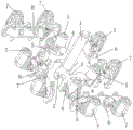
FIG. 1 is a schematic structural view of an embodiment of the casting method of the heat-resistant cast steel thin-walled exhaust manifold of the present invention;
FIG. 2 is a top view of FIG. 1;
FIG. 3 is a sectional view taken along line A-A of FIG. 2;
4a, 4b and 4c are schematic diagrams of ProCAST pouring and filling simulation analysis of the casting method of the heat-resistant cast steel thin-wall exhaust manifold;
FIG. 5 is a diagram showing the effect of the casting produced by the casting method of the heat-resistant cast steel thin-walled exhaust manifold according to the present invention;
FIG. 6 is a sectional view taken along line B-B of FIG. 2;
FIG. 7 is a schematic view of the gating system of the casting method of the heat resistant cast steel thin wall exhaust manifold of the present invention;
FIG. 8 is a schematic view of another perspective of the gating system of the method of casting the heat resistant cast steel thin wall exhaust manifold of the present invention;
FIG. 9 is a schematic structural view of a sand mold of the casting method of the heat-resistant cast steel thin-walled exhaust manifold of the present invention;
reference numerals:
1: a sprue; 2: a cross gate; 3: an inner pouring channel; 4: a slag-avoiding net; 5: feeding a fire riser; 6: a casting cavity; 7: an overflow riser; 8: the junction between the fire inlet riser and the casting cavity; 9 a buffer tank; 10: putting a sand mold; 11: a sand mold is put; 12: an upper shell core; 13: a lower shell core; 14: an air cavity core.
Detailed Description
In order to make the aforementioned objects, features and advantages of the present invention comprehensible, embodiments accompanied with figures are described in detail below. In the following description, numerous specific details are set forth in order to provide a thorough understanding of the present invention. The present invention can be embodied in many different forms than those herein described and it will be apparent to those skilled in the art that similar modifications can be made without departing from the spirit and scope of the invention and, therefore, the invention is not to be limited to the embodiments set forth herein.
It will be understood that when an element is referred to as being "secured to" another element, it can be directly on the other element or intervening elements may also be present. When an element is referred to as being "connected" to another element, it can be directly connected to the other element or intervening elements may also be present. The terms "vertical," "horizontal," "left," "right," and similar expressions are used herein for illustrative purposes only and do not represent the only embodiments.
Unless defined otherwise, all technical and scientific terms used herein have the same meaning as commonly understood by one of ordinary skill in the art to which this invention belongs. The terminology used in the description of the invention herein is for the purpose of describing particular embodiments only and is not intended to be limiting of the invention. As used herein, the term "and/or" includes any and all combinations of one or more of the associated listed items.
An embodiment of a method for casting a heat-resistant cast steel thin-walled exhaust manifold according to the present invention, as shown in fig. 1 to 3, 4a, 4b, 4c, 5, and 9, includes a sand mold making step, a molten steel melting step, and a pouring step, in which: including making sand mould 10, lower sand mould 11, still including the preparation setting go up the sand core that sets up between sand mould 10, the lower sand mould 11, the sand core includes epitheca core 12, inferior valve core 13, is provided with the air cavity core 14 that is used for forming foundry goods die cavity 6 between epitheca core 12, inferior valve core 13, in the sand mould preparation step:
the pouring system comprises a sprue 1 and a cross gate 2, wherein one end of the cross gate 2 is vertically communicated with the sprue 1, the other end of the cross gate is communicated with an ingate 3, a slag avoiding net 4 is arranged on the ingate 3, the ingate 3 is communicated with a cavity, a fire inlet riser 5 is arranged at a position between the ingate 3 and the cavity, and the pouring system also comprises an overflow riser 7 positioned at the tail end of the cavity; in order to ensure that molten steel stably and quickly enters a casting cavity 6, the horizontal pouring channel 2, the slag avoiding net 4 and the inner pouring channel 3 are all arranged at the position of a lower cavity of the sand mold, and particularly, the height of the horizontal pouring channel 2, the slag avoiding net 4 and the inner pouring channel 3 in the vertical direction is not more than the height of a parting line in the horizontal direction of the casting cavity 6; the ingate 3 is communicated with the middle part of the horizontal runner 2, so that the flow speed of molten steel is stable when the molten steel enters the ingate 3, the slag avoiding net 4 is specifically a ceramic slag avoiding net, specifically, the hole density is 6-10PPI, the area of the hole density is 2.5-4.5 times of the cross section area of the ingate, the hole density in the embodiment is 7PPI, and the area of the hole density is 3 times of the cross section area of the ingate.
The casting method provided by the invention also comprises a molten steel smelting step, wherein the temperature of the molten steel smelting furnace is controlled at 1700 ℃ and 1710 ℃, and specifically can be 1710 ℃; the first box pouring temperature is 1645 ℃; the pouring speed is 6.5-7.5kg/s, and the concrete speed can be 7.5 kg/s; the cooling time is more than or equal to 50min, and the cooling time in the embodiment is 60 min.
In order to avoid that the gas exhaust speed is slow in the pouring process and the quality of the castings is influenced, the number of the overflow risers 7 is larger than the number of the castings prepared by the sand mold; in order to meet production requirements, in the pouring step, the sand mold is one-type one-piece or the sand mold is a plurality of one-type sand molds, and batch production can be carried out.
According to the casting method of the heat-resistant cast steel thin-wall exhaust manifold, the cross runner 2, the slag avoiding net 4 and the inner runner 3 are arranged in the lower cavity of the sand mold in the sand mold manufacturing step, so that molten steel can be stably and quickly filled into the cavity in the pouring process, the slag avoiding net 4 is arranged to effectively filter the steel slag or impurities in the molten steel, and the quality stability of a cast piece during molding is further ensured; in addition, the pouring system is provided with the fire inlet risers 5 and the plurality of overflow risers 7, so that gas in the cavity can be discharged smoothly, the intersection of molten steel flow heads is avoided, the cold shut problem and the choking and skinning problem of castings are effectively solved, and the whole pouring body system has the characteristics of reasonable design, stable molten steel flow rate and high casting yield and is particularly suitable for the exhaust manifold castings with complex thin walls.
In the sand mold manufacturing step in this embodiment, one mold with four parts is adopted, and 4 air cavity cores 14 are respectively arranged in the sand mold, and the corresponding cavities for forming four castings are distributed at the circumferential position of the sprue 1. Specifically, the casting cavities 6 are distributed in a centrosymmetric manner by taking the position of the sprue 1 as the center, and have better structural rationality compared with the traditional bilateral symmetric distribution.
In this embodiment, two runners 2 are respectively distributed on two sides of the sprue 1, specifically, the two runners are distributed in a central symmetry manner at the position of the sprue 1; in order to meet the production requirements of one mould with four parts, when the ingate 3 is arranged, the shape of the ingate 3 is a herringbone shape used for dividing the molten steel in the corresponding cross gate 2 into two parts.
In this embodiment, the number of the feeder heads 5 is the same as the number of castings manufactured by a sand mold, in this embodiment, the diameter of the feeder heads 5 is 48mm, the height of the feeder heads is 97mm, and the number of the relief heads 7 is twice as large as the number of castings manufactured by a sand mold, specifically, in this embodiment, taking four molds as an example, the number of the feeder heads 5 is 4, and the number of the relief heads 7 is 8, wherein the relief heads 7 are arranged at branch pipe positions of an exhaust manifold, two adjacent branch pipe cavities converge to one relief head 7, and converge from adjacent pipe walls of two adjacent branch pipes for later-stage cutting.
In order to further stabilize the flow velocity of the molten steel, the cross sections of the runner 2 and the ingate 3 in this embodiment are formed into flared structures which facilitate smooth flow of the molten steel.
In the embodiment, in order to meet the casting requirement and reduce the cost, the upper shell, the lower shell and the air cavity core 14 all adopt precoated sand, the sand mold adopts green sand, and a green sand shell mold process is adopted, wherein the precoated sand adopts special sand (FMS-XII 40/70), and the specific performance is that SiO2 is more than or equal to 90%; melting point 97-106 ℃; the gas forming amount is less than or equal to 15 ml/g; the ignition decrement is less than or equal to 3.5 percent; the tensile strength at normal temperature is more than or equal to 4.5 MPa; the bending strength is more than or equal to 8.5 MPa; the thermal tensile strength is more than or equal to 1.6 MPa; the thermal-state bending strength is more than or equal to 3.6 MPa; the mesh number is 40-70 meshes which is more than or equal to 75 percent.
The green sand has the specific properties of 01-0.18MPa of wet compression strength, 32-36 percent of compaction rate, 2.5-3.0 percent of water, 100 percent of air permeability, 170 percent of mud content, 7-10 percent of effective bentonite content and more than or equal to 90HBW of sand mold hardness.
As shown in fig. 4a, 4b and 4c, through the simulation analysis of casting and mold filling, the mold filling is smooth and basically has no confluent point of molten steel, and the molten steel overflows to the overflow head 7 in sequence. And the gas in the cavity is sequentially discharged to the corresponding risers, and no isolated gas pocket is formed at the position of the pipe wall.
The casting method provided by the invention can meet the requirements of exhaust manifolds with various wall thicknesses, particularly the exhaust manifolds with thin walls and uneven wall thicknesses, and the pouring system provided by the invention can ensure that molten steel flows stably and quickly, the exhaust is smooth, and the casting quality is stable. The wall thickness of the exhaust manifold in the embodiment is 4 +/-0.5 mm, and the local wall thickness is 4-35 mm.
As shown in fig. 6 to 8, when the sprue, the runner 2, and the ingate 3 are provided, the ratio of the cross-sectional areas of the three is 1: (1.1-1.3): (0.6-0.9), in the present embodiment, the ratio of the cross-sectional areas of the three is 1:1.2:0.7, the specific size being the cross-sectional area of the straight pouring cup being 1590 mm; the cross-sectional area of the runner 2 is: 1860 mm; the cross-sectional area of the ingate 3 is 1150 mm. In addition, in order to avoid the fire feeder 5 from forming choked flow, a large-caliber riser neck is adopted in the present embodiment, specifically, the riser neck sectional area 3725mm in the present embodiment is larger than the straight pouring cup sectional area 1590 mm; in order to make the molten steel rapidly flow into the casting cavity 6, the connection 8 between the feeder head 4 and the casting cavity 6 is in a C shape, and the sectional area of the C shape is 3725.80 mm.
In order to stably divide molten steel at the connection between the sprue 1, the runner 2 and the ingate 3, the diameter D of the sprue 1, the width W1 of the runner 2 and the width W2 of the ingate 3 are gradually reduced, specifically, the diameter D of the sprue 1 in the embodiment: 45mm, width W1 of the runner 2: 30mm and a width W2:25.64mm of the ingate 3 (width of a joint with the runner 2), and on the other hand, the upper ends of the runner 2 and the ingate 3 are flush with each other in the vertical direction, the height H2 of the runner 2 is 35mm, the height H3 of the ingate 3 is 25mm, and the height H1 of the sprue 1 is: 200 mm; a buffer groove 9 which is concave downwards is arranged below the sprue 1 on the cross gate 2, and the buffer groove 9 is a curved groove.
In other embodiments of the present invention, in the sand mold making step, a mold with two or 6 pieces can be made; the number of the overflow risers corresponding to each casting can be two, 3 or 4; the slag avoiding net can be arranged at the position of the cross gate; the ingate can divide the molten steel in the cross gate into two parts by respectively arranging the ingate at two sides of the cross gate.
An embodiment of the sand mold for casting a heat-resistant cast steel thin-walled exhaust manifold of the present invention.
A sand mould for casting a heat-resistant cast steel thin-wall exhaust manifold comprises an upper sand mould and a lower sand mould, and further comprises a sand core arranged between the upper sand mould and the lower sand mould, wherein the sand core comprises an upper shell core and a lower shell core, and further comprises an air cavity core arranged between the upper shell core and the lower shell core and used for forming a casting cavity, a pouring system is arranged on the sand mould, and the pouring system is the same as that in the embodiment of the casting method of the heat-resistant cast steel thin-wall exhaust manifold, and is not described again.
The above-mentioned embodiments only express several embodiments of the present invention, and the description thereof is more specific and detailed, but not construed as limiting the scope of the present invention. It should be noted that, for a person skilled in the art, several variations and modifications can be made without departing from the inventive concept, which falls within the scope of the present invention. Therefore, the protection scope of the present patent shall be subject to the appended claims.
Claims (9)
1. A casting method of a heat-resistant cast steel thin-wall exhaust manifold comprises the steps of sand mold manufacturing, molten steel smelting and pouring, wherein in the sand mold manufacturing step: including making sand mould, lower sand mould, still set up including the preparation go up the psammitolite that sets up between sand mould, the lower sand mould, the psammitolite includes epitheca core, lower shell core, be provided with the air cavity core that is used for forming the foundry goods die cavity between epitheca core, the lower shell core, be provided with the gating system on the sand mould, its characterized in that:
in the sand mold manufacturing step:
the gating system comprises a sprue and a cross gate, one end of the cross gate is vertically communicated with the sprue, the other end of the cross gate is communicated with an ingate, a slag avoiding net is arranged on the ingate, the ingate is communicated with a cavity, the ingate is provided with a fire inlet riser at a position between the cavity and the cavity, the gating system further comprises an overflow riser positioned at the tail end of the cavity, the diameter of the sprue, the width of the cross gate and the width of the ingate are gradually reduced, and the cross-sectional area proportion of the sprue, the cross gate and the ingate is sequentially 1: (1.1-1.3): (0.6-0.9), a buffer groove which is concave downwards is arranged below the sprue on the cross runner;
the horizontal pouring gate, the slag avoiding net and the inner pouring gate are all arranged on the lower sand mold, the horizontal pouring gate and the inner pouring gate are positioned on the lower cavity and close to the upper cavity, namely, the horizontal pouring gate and the inner pouring gate are positioned on the middle line of the whole shell core, and the inner pouring gate is communicated with the middle part of the horizontal pouring gate;
the connection part between the fire feeding riser and the cavity is C-shaped, and the C-shaped part extends to one side of the section from the bottom of the section on the section of the cavity;
the upper shell core, the lower shell core and the air cavity core all adopt precoated sand, and the upper sand mold and the lower sand mold adopt green sand;
the number of the overflow risers is larger than the number of castings prepared by the sand mold;
in the pouring step, the first sand mould is one piece; or the sand mold is a plurality of pieces.
2. The casting method of a heat-resistant cast steel thin-walled exhaust manifold as claimed in claim 1, characterized in that: in the sand mold manufacturing step, one mold with four parts is adopted, and corresponding cavities for forming four castings are distributed at the circumferential position of the sprue.
3. The casting method of the heat-resistant cast steel thin-walled exhaust manifold as claimed in claim 2, characterized in that: the number of the transverse pouring channels is two, the transverse pouring channels are respectively distributed on two sides of the straight pouring channel, and the inner pouring channel is of a herringbone shape and is used for dividing molten steel in the corresponding transverse pouring channel into two parts.
4. The casting method of the heat-resistant cast steel thin-walled exhaust manifold as claimed in claim 3, characterized in that: the number of the fire feeding risers is the same as the number of castings manufactured by the sand mold.
5. The casting method of the heat-resistant cast steel thin-walled exhaust manifold as claimed in claim 4, characterized in that: the number of the overflow risers is twice of the number of castings manufactured by the sand mold.
6. The casting method of a heat-resistant cast steel thin-walled exhaust manifold according to any one of claims 1 to 5, characterized in that: the cross section of the horizontal pouring channel is of a flaring structure which is convenient for enabling molten steel to flow stably.
7. The casting method of a heat-resistant cast steel thin-walled exhaust manifold according to any one of claims 1 to 5, characterized in that: the cross section of the ingate is of a flaring structure which is convenient for the molten steel to flow stably.
8. The casting method of a heat-resistant cast steel thin-walled exhaust manifold according to any one of claims 1 to 5, characterized in that: the slag avoiding net is a ceramic slag avoiding net.
9. The utility model provides a sand mould is used in casting of heat-resisting cast steel thin wall exhaust manifold, includes sand mould, lower sand mould, still including setting up the psammitolite between last sand mould, the lower sand mould, the psammitolite includes epitheca core, lower shell core, still including setting up the air cavity core that is used for forming the foundry goods die cavity between epitheca core, the lower shell core, be provided with the gating system on the sand mould, its characterized in that: the gating system according to any one of the preceding claims 1 to 8.
Priority Applications (1)
| Application Number | Priority Date | Filing Date | Title |
|---|---|---|---|
| CN201911326581.7A CN111421115B (en) | 2019-12-20 | 2019-12-20 | Casting method of heat-resistant cast steel thin-wall exhaust manifold and sand mould for casting |
Applications Claiming Priority (1)
| Application Number | Priority Date | Filing Date | Title |
|---|---|---|---|
| CN201911326581.7A CN111421115B (en) | 2019-12-20 | 2019-12-20 | Casting method of heat-resistant cast steel thin-wall exhaust manifold and sand mould for casting |
Publications (2)
| Publication Number | Publication Date |
|---|---|
| CN111421115A CN111421115A (en) | 2020-07-17 |
| CN111421115B true CN111421115B (en) | 2021-12-14 |
Family
ID=71545832
Family Applications (1)
| Application Number | Title | Priority Date | Filing Date |
|---|---|---|---|
| CN201911326581.7A Active CN111421115B (en) | 2019-12-20 | 2019-12-20 | Casting method of heat-resistant cast steel thin-wall exhaust manifold and sand mould for casting |
Country Status (1)
| Country | Link |
|---|---|
| CN (1) | CN111421115B (en) |
Families Citing this family (2)
| Publication number | Priority date | Publication date | Assignee | Title |
|---|---|---|---|---|
| CN111804876B (en) * | 2020-07-20 | 2021-08-24 | 东风汽车股份有限公司 | Eight formula watering foundry goods moulds in a mould |
| CN113618019B (en) * | 2021-08-26 | 2023-04-07 | 共享智能铸造产业创新中心(潍坊)有限公司 | Casting method of double-layer exhaust pipe casting |
Citations (10)
| Publication number | Priority date | Publication date | Assignee | Title |
|---|---|---|---|---|
| CN201324826Y (en) * | 2009-01-23 | 2009-10-14 | 宁波埃利特模具制造有限公司 | Aluminum alloy die-cast pouring and arranging structure of engine suspension support |
| CN201841251U (en) * | 2010-08-04 | 2011-05-25 | 徐州徐航压铸有限公司 | Four cylinder engine die-casting gate, gate runner structure |
| CN203817295U (en) * | 2014-04-14 | 2014-09-10 | 西峡县内燃机进排气管有限责任公司 | Casting model of water-jacket type exhaust manifold applicable to marine engine |
| CN203875291U (en) * | 2014-04-19 | 2014-10-15 | 西峡县内燃机进排气管有限责任公司 | Exhaust manifold casting mold |
| CN204018646U (en) * | 2014-07-11 | 2014-12-17 | 合肥江淮铸造有限责任公司 | A kind of vermicular cast iron brake drum running gate system |
| CN105478667A (en) * | 2014-02-28 | 2016-04-13 | 郑州思辩科技有限公司 | Manufacturing method of water jacket type exhaust manifold casting sand mold |
| CN205904387U (en) * | 2016-08-15 | 2017-01-25 | 西峡县内燃机进排气管有限责任公司 | Nickelic magnesium iron blast pipe the gating system |
| CN108655348A (en) * | 2018-06-08 | 2018-10-16 | 南阳飞龙汽车零部件有限公司 | A kind of heavy wall cast steel exhaust manifold casting technique |
| CN109128032A (en) * | 2018-11-06 | 2019-01-04 | 西峡县内燃机进排气管有限责任公司 | A kind of high-nickel austenite nodular cast iron exhaust pipe of engine back is into fire process |
| CN209077721U (en) * | 2018-05-15 | 2019-07-09 | 驻马店中集华骏铸造有限公司 | A kind of improvement property brake drum running gate system |
Family Cites Families (1)
| Publication number | Priority date | Publication date | Assignee | Title |
|---|---|---|---|---|
| CN109570440A (en) * | 2019-01-30 | 2019-04-05 | 西峡县西泵特种铸造有限公司 | A kind of casting mould increasing mold thickness |
-
2019
- 2019-12-20 CN CN201911326581.7A patent/CN111421115B/en active Active
Patent Citations (10)
| Publication number | Priority date | Publication date | Assignee | Title |
|---|---|---|---|---|
| CN201324826Y (en) * | 2009-01-23 | 2009-10-14 | 宁波埃利特模具制造有限公司 | Aluminum alloy die-cast pouring and arranging structure of engine suspension support |
| CN201841251U (en) * | 2010-08-04 | 2011-05-25 | 徐州徐航压铸有限公司 | Four cylinder engine die-casting gate, gate runner structure |
| CN105478667A (en) * | 2014-02-28 | 2016-04-13 | 郑州思辩科技有限公司 | Manufacturing method of water jacket type exhaust manifold casting sand mold |
| CN203817295U (en) * | 2014-04-14 | 2014-09-10 | 西峡县内燃机进排气管有限责任公司 | Casting model of water-jacket type exhaust manifold applicable to marine engine |
| CN203875291U (en) * | 2014-04-19 | 2014-10-15 | 西峡县内燃机进排气管有限责任公司 | Exhaust manifold casting mold |
| CN204018646U (en) * | 2014-07-11 | 2014-12-17 | 合肥江淮铸造有限责任公司 | A kind of vermicular cast iron brake drum running gate system |
| CN205904387U (en) * | 2016-08-15 | 2017-01-25 | 西峡县内燃机进排气管有限责任公司 | Nickelic magnesium iron blast pipe the gating system |
| CN209077721U (en) * | 2018-05-15 | 2019-07-09 | 驻马店中集华骏铸造有限公司 | A kind of improvement property brake drum running gate system |
| CN108655348A (en) * | 2018-06-08 | 2018-10-16 | 南阳飞龙汽车零部件有限公司 | A kind of heavy wall cast steel exhaust manifold casting technique |
| CN109128032A (en) * | 2018-11-06 | 2019-01-04 | 西峡县内燃机进排气管有限责任公司 | A kind of high-nickel austenite nodular cast iron exhaust pipe of engine back is into fire process |
Also Published As
| Publication number | Publication date |
|---|---|
| CN111421115A (en) | 2020-07-17 |
Similar Documents
| Publication | Publication Date | Title |
|---|---|---|
| CN102554130B (en) | Casting method for high-nickel austenite nodular cast iron exhaust manifold | |
| CN111421115B (en) | Casting method of heat-resistant cast steel thin-wall exhaust manifold and sand mould for casting | |
| CN107931543B (en) | Tubular thin-wall steel piece casting mold and design method thereof | |
| CN103736928A (en) | Evanescent mode pouring system of speed changing box body | |
| CN111112558A (en) | Baffle sand core casting system for high-precision clutch flange plate | |
| CN109500375B (en) | Faucet casting process | |
| CN109128032B (en) | High-nickel austenitic ductile iron engine exhaust pipe back fire feeding process | |
| CN214640101U (en) | Lock connecting sheet investment casting tree assembling structure | |
| CN107891124B (en) | Loader cylinder head lost foam provided with multiple arch bridge cross runners and casting process | |
| CN110238347B (en) | Casting system for lost foam casting cam shaft | |
| CN209110156U (en) | Shell moulded casting device of the vacuum in conjunction with pressure | |
| CN218425441U (en) | Pouring system of crankcase | |
| CN113828735B (en) | Pouring system and investment casting process of high-temperature alloy elbow | |
| CN210547852U (en) | Pouring system for lost foam casting camshaft | |
| CN209830192U (en) | Investment mold of coupler lock for locomotive coupler | |
| CN208483212U (en) | A kind of shell structure that suction pouring ingate quickly solidifies | |
| CN111687376A (en) | Bottom pouring cap structure | |
| CN212945277U (en) | Annular casting pouring system | |
| CN214640082U (en) | Umbrella-shaped insert investment casting structure | |
| CN218080350U (en) | Hollow sand core with inner runner for gold sand type low-pressure casting aluminum shell | |
| CN219598016U (en) | Novel spiral tooth casting | |
| CN216680104U (en) | Gating system of thin-wall casting | |
| CN216938286U (en) | Sand mould system of large plane casting | |
| RU109030U1 (en) | CASTING FORM FOR CASTING OF LONG CASTINGS FROM ALUMINUM ALLOYS WITH A WIDE CRYSTALIZATION INTERVAL | |
| CN110586872B (en) | Casting system of hollow slab steel casting for valve and design method thereof |
Legal Events
| Date | Code | Title | Description |
|---|---|---|---|
| PB01 | Publication | ||
| PB01 | Publication | ||
| SE01 | Entry into force of request for substantive examination | ||
| SE01 | Entry into force of request for substantive examination | ||
| GR01 | Patent grant | ||
| GR01 | Patent grant |