CN111417552B - Service and emergency braking control systems for at least one railway vehicle - Google Patents
Service and emergency braking control systems for at least one railway vehicle Download PDFInfo
- Publication number
- CN111417552B CN111417552B CN201880059281.4A CN201880059281A CN111417552B CN 111417552 B CN111417552 B CN 111417552B CN 201880059281 A CN201880059281 A CN 201880059281A CN 111417552 B CN111417552 B CN 111417552B
- Authority
- CN
- China
- Prior art keywords
- braking
- value
- control module
- railway vehicle
- brake
- Prior art date
- Legal status (The legal status is an assumption and is not a legal conclusion. Google has not performed a legal analysis and makes no representation as to the accuracy of the status listed.)
- Active
Links
Images


Classifications
-
- B—PERFORMING OPERATIONS; TRANSPORTING
- B60—VEHICLES IN GENERAL
- B60T—VEHICLE BRAKE CONTROL SYSTEMS OR PARTS THEREOF; BRAKE CONTROL SYSTEMS OR PARTS THEREOF, IN GENERAL; ARRANGEMENT OF BRAKING ELEMENTS ON VEHICLES IN GENERAL; PORTABLE DEVICES FOR PREVENTING UNWANTED MOVEMENT OF VEHICLES; VEHICLE MODIFICATIONS TO FACILITATE COOLING OF BRAKES
- B60T7/00—Brake-action initiating means
- B60T7/12—Brake-action initiating means for automatic initiation; for initiation not subject to will of driver or passenger
- B60T7/126—Brakes for railway vehicles coming into operation in case of exceeding a predetermined speed
-
- B—PERFORMING OPERATIONS; TRANSPORTING
- B60—VEHICLES IN GENERAL
- B60T—VEHICLE BRAKE CONTROL SYSTEMS OR PARTS THEREOF; BRAKE CONTROL SYSTEMS OR PARTS THEREOF, IN GENERAL; ARRANGEMENT OF BRAKING ELEMENTS ON VEHICLES IN GENERAL; PORTABLE DEVICES FOR PREVENTING UNWANTED MOVEMENT OF VEHICLES; VEHICLE MODIFICATIONS TO FACILITATE COOLING OF BRAKES
- B60T13/00—Transmitting braking action from initiating means to ultimate brake actuator with power assistance or drive; Brake systems incorporating such transmitting means, e.g. air-pressure brake systems
- B60T13/10—Transmitting braking action from initiating means to ultimate brake actuator with power assistance or drive; Brake systems incorporating such transmitting means, e.g. air-pressure brake systems with fluid assistance, drive, or release
- B60T13/58—Combined or convertible systems
- B60T13/585—Combined or convertible systems comprising friction brakes and retarders
- B60T13/586—Combined or convertible systems comprising friction brakes and retarders the retarders being of the electric type
-
- B—PERFORMING OPERATIONS; TRANSPORTING
- B60—VEHICLES IN GENERAL
- B60T—VEHICLE BRAKE CONTROL SYSTEMS OR PARTS THEREOF; BRAKE CONTROL SYSTEMS OR PARTS THEREOF, IN GENERAL; ARRANGEMENT OF BRAKING ELEMENTS ON VEHICLES IN GENERAL; PORTABLE DEVICES FOR PREVENTING UNWANTED MOVEMENT OF VEHICLES; VEHICLE MODIFICATIONS TO FACILITATE COOLING OF BRAKES
- B60T13/00—Transmitting braking action from initiating means to ultimate brake actuator with power assistance or drive; Brake systems incorporating such transmitting means, e.g. air-pressure brake systems
- B60T13/10—Transmitting braking action from initiating means to ultimate brake actuator with power assistance or drive; Brake systems incorporating such transmitting means, e.g. air-pressure brake systems with fluid assistance, drive, or release
- B60T13/66—Electrical control in fluid-pressure brake systems
- B60T13/662—Electrical control in fluid-pressure brake systems characterised by specified functions of the control system components
-
- B—PERFORMING OPERATIONS; TRANSPORTING
- B60—VEHICLES IN GENERAL
- B60T—VEHICLE BRAKE CONTROL SYSTEMS OR PARTS THEREOF; BRAKE CONTROL SYSTEMS OR PARTS THEREOF, IN GENERAL; ARRANGEMENT OF BRAKING ELEMENTS ON VEHICLES IN GENERAL; PORTABLE DEVICES FOR PREVENTING UNWANTED MOVEMENT OF VEHICLES; VEHICLE MODIFICATIONS TO FACILITATE COOLING OF BRAKES
- B60T13/00—Transmitting braking action from initiating means to ultimate brake actuator with power assistance or drive; Brake systems incorporating such transmitting means, e.g. air-pressure brake systems
- B60T13/10—Transmitting braking action from initiating means to ultimate brake actuator with power assistance or drive; Brake systems incorporating such transmitting means, e.g. air-pressure brake systems with fluid assistance, drive, or release
- B60T13/66—Electrical control in fluid-pressure brake systems
- B60T13/665—Electrical control in fluid-pressure brake systems the systems being specially adapted for transferring two or more command signals, e.g. railway systems
- B60T13/667—Electrical control in fluid-pressure brake systems the systems being specially adapted for transferring two or more command signals, e.g. railway systems and combined with electro-magnetic brakes
-
- B—PERFORMING OPERATIONS; TRANSPORTING
- B60—VEHICLES IN GENERAL
- B60T—VEHICLE BRAKE CONTROL SYSTEMS OR PARTS THEREOF; BRAKE CONTROL SYSTEMS OR PARTS THEREOF, IN GENERAL; ARRANGEMENT OF BRAKING ELEMENTS ON VEHICLES IN GENERAL; PORTABLE DEVICES FOR PREVENTING UNWANTED MOVEMENT OF VEHICLES; VEHICLE MODIFICATIONS TO FACILITATE COOLING OF BRAKES
- B60T7/00—Brake-action initiating means
- B60T7/12—Brake-action initiating means for automatic initiation; for initiation not subject to will of driver or passenger
-
- B—PERFORMING OPERATIONS; TRANSPORTING
- B60—VEHICLES IN GENERAL
- B60T—VEHICLE BRAKE CONTROL SYSTEMS OR PARTS THEREOF; BRAKE CONTROL SYSTEMS OR PARTS THEREOF, IN GENERAL; ARRANGEMENT OF BRAKING ELEMENTS ON VEHICLES IN GENERAL; PORTABLE DEVICES FOR PREVENTING UNWANTED MOVEMENT OF VEHICLES; VEHICLE MODIFICATIONS TO FACILITATE COOLING OF BRAKES
- B60T8/00—Arrangements for adjusting wheel-braking force to meet varying vehicular or ground-surface conditions, e.g. limiting or varying distribution of braking force
- B60T8/17—Using electrical or electronic regulation means to control braking
- B60T8/1701—Braking or traction control means specially adapted for particular types of vehicles
- B60T8/1705—Braking or traction control means specially adapted for particular types of vehicles for rail vehicles
-
- B—PERFORMING OPERATIONS; TRANSPORTING
- B60—VEHICLES IN GENERAL
- B60T—VEHICLE BRAKE CONTROL SYSTEMS OR PARTS THEREOF; BRAKE CONTROL SYSTEMS OR PARTS THEREOF, IN GENERAL; ARRANGEMENT OF BRAKING ELEMENTS ON VEHICLES IN GENERAL; PORTABLE DEVICES FOR PREVENTING UNWANTED MOVEMENT OF VEHICLES; VEHICLE MODIFICATIONS TO FACILITATE COOLING OF BRAKES
- B60T8/00—Arrangements for adjusting wheel-braking force to meet varying vehicular or ground-surface conditions, e.g. limiting or varying distribution of braking force
- B60T8/17—Using electrical or electronic regulation means to control braking
- B60T8/171—Detecting parameters used in the regulation; Measuring values used in the regulation
-
- B—PERFORMING OPERATIONS; TRANSPORTING
- B60—VEHICLES IN GENERAL
- B60T—VEHICLE BRAKE CONTROL SYSTEMS OR PARTS THEREOF; BRAKE CONTROL SYSTEMS OR PARTS THEREOF, IN GENERAL; ARRANGEMENT OF BRAKING ELEMENTS ON VEHICLES IN GENERAL; PORTABLE DEVICES FOR PREVENTING UNWANTED MOVEMENT OF VEHICLES; VEHICLE MODIFICATIONS TO FACILITATE COOLING OF BRAKES
- B60T8/00—Arrangements for adjusting wheel-braking force to meet varying vehicular or ground-surface conditions, e.g. limiting or varying distribution of braking force
- B60T8/17—Using electrical or electronic regulation means to control braking
- B60T8/172—Determining control parameters used in the regulation, e.g. by calculations involving measured or detected parameters
-
- B—PERFORMING OPERATIONS; TRANSPORTING
- B60—VEHICLES IN GENERAL
- B60T—VEHICLE BRAKE CONTROL SYSTEMS OR PARTS THEREOF; BRAKE CONTROL SYSTEMS OR PARTS THEREOF, IN GENERAL; ARRANGEMENT OF BRAKING ELEMENTS ON VEHICLES IN GENERAL; PORTABLE DEVICES FOR PREVENTING UNWANTED MOVEMENT OF VEHICLES; VEHICLE MODIFICATIONS TO FACILITATE COOLING OF BRAKES
- B60T8/00—Arrangements for adjusting wheel-braking force to meet varying vehicular or ground-surface conditions, e.g. limiting or varying distribution of braking force
- B60T8/17—Using electrical or electronic regulation means to control braking
- B60T8/176—Brake regulation specially adapted to prevent excessive wheel slip during vehicle deceleration, e.g. ABS
- B60T8/1763—Brake regulation specially adapted to prevent excessive wheel slip during vehicle deceleration, e.g. ABS responsive to the coefficient of friction between the wheels and the ground surface
- B60T8/17636—Microprocessor-based systems
-
- B—PERFORMING OPERATIONS; TRANSPORTING
- B60—VEHICLES IN GENERAL
- B60T—VEHICLE BRAKE CONTROL SYSTEMS OR PARTS THEREOF; BRAKE CONTROL SYSTEMS OR PARTS THEREOF, IN GENERAL; ARRANGEMENT OF BRAKING ELEMENTS ON VEHICLES IN GENERAL; PORTABLE DEVICES FOR PREVENTING UNWANTED MOVEMENT OF VEHICLES; VEHICLE MODIFICATIONS TO FACILITATE COOLING OF BRAKES
- B60T8/00—Arrangements for adjusting wheel-braking force to meet varying vehicular or ground-surface conditions, e.g. limiting or varying distribution of braking force
- B60T8/18—Arrangements for adjusting wheel-braking force to meet varying vehicular or ground-surface conditions, e.g. limiting or varying distribution of braking force responsive to vehicle weight or load, e.g. load distribution
- B60T8/1893—Arrangements for adjusting wheel-braking force to meet varying vehicular or ground-surface conditions, e.g. limiting or varying distribution of braking force responsive to vehicle weight or load, e.g. load distribution especially adapted for railway vehicles
-
- B—PERFORMING OPERATIONS; TRANSPORTING
- B60—VEHICLES IN GENERAL
- B60T—VEHICLE BRAKE CONTROL SYSTEMS OR PARTS THEREOF; BRAKE CONTROL SYSTEMS OR PARTS THEREOF, IN GENERAL; ARRANGEMENT OF BRAKING ELEMENTS ON VEHICLES IN GENERAL; PORTABLE DEVICES FOR PREVENTING UNWANTED MOVEMENT OF VEHICLES; VEHICLE MODIFICATIONS TO FACILITATE COOLING OF BRAKES
- B60T8/00—Arrangements for adjusting wheel-braking force to meet varying vehicular or ground-surface conditions, e.g. limiting or varying distribution of braking force
- B60T8/32—Arrangements for adjusting wheel-braking force to meet varying vehicular or ground-surface conditions, e.g. limiting or varying distribution of braking force responsive to a speed condition, e.g. acceleration or deceleration
- B60T8/321—Arrangements for adjusting wheel-braking force to meet varying vehicular or ground-surface conditions, e.g. limiting or varying distribution of braking force responsive to a speed condition, e.g. acceleration or deceleration deceleration
- B60T8/3235—Systems specially adapted for rail vehicles
- B60T8/3245—Systems specially adapted for rail vehicles responsive to the speed difference between wheels and rail, or between two wheels or two axles
-
- B—PERFORMING OPERATIONS; TRANSPORTING
- B60—VEHICLES IN GENERAL
- B60T—VEHICLE BRAKE CONTROL SYSTEMS OR PARTS THEREOF; BRAKE CONTROL SYSTEMS OR PARTS THEREOF, IN GENERAL; ARRANGEMENT OF BRAKING ELEMENTS ON VEHICLES IN GENERAL; PORTABLE DEVICES FOR PREVENTING UNWANTED MOVEMENT OF VEHICLES; VEHICLE MODIFICATIONS TO FACILITATE COOLING OF BRAKES
- B60T8/00—Arrangements for adjusting wheel-braking force to meet varying vehicular or ground-surface conditions, e.g. limiting or varying distribution of braking force
- B60T8/32—Arrangements for adjusting wheel-braking force to meet varying vehicular or ground-surface conditions, e.g. limiting or varying distribution of braking force responsive to a speed condition, e.g. acceleration or deceleration
- B60T8/72—Arrangements for adjusting wheel-braking force to meet varying vehicular or ground-surface conditions, e.g. limiting or varying distribution of braking force responsive to a speed condition, e.g. acceleration or deceleration responsive to a difference between a speed condition, e.g. deceleration, and a fixed reference
- B60T8/74—Arrangements for adjusting wheel-braking force to meet varying vehicular or ground-surface conditions, e.g. limiting or varying distribution of braking force responsive to a speed condition, e.g. acceleration or deceleration responsive to a difference between a speed condition, e.g. deceleration, and a fixed reference sensing a rate of change of velocity
-
- B—PERFORMING OPERATIONS; TRANSPORTING
- B60—VEHICLES IN GENERAL
- B60T—VEHICLE BRAKE CONTROL SYSTEMS OR PARTS THEREOF; BRAKE CONTROL SYSTEMS OR PARTS THEREOF, IN GENERAL; ARRANGEMENT OF BRAKING ELEMENTS ON VEHICLES IN GENERAL; PORTABLE DEVICES FOR PREVENTING UNWANTED MOVEMENT OF VEHICLES; VEHICLE MODIFICATIONS TO FACILITATE COOLING OF BRAKES
- B60T2250/00—Monitoring, detecting, estimating vehicle conditions
- B60T2250/02—Vehicle mass
-
- B—PERFORMING OPERATIONS; TRANSPORTING
- B60—VEHICLES IN GENERAL
- B60T—VEHICLE BRAKE CONTROL SYSTEMS OR PARTS THEREOF; BRAKE CONTROL SYSTEMS OR PARTS THEREOF, IN GENERAL; ARRANGEMENT OF BRAKING ELEMENTS ON VEHICLES IN GENERAL; PORTABLE DEVICES FOR PREVENTING UNWANTED MOVEMENT OF VEHICLES; VEHICLE MODIFICATIONS TO FACILITATE COOLING OF BRAKES
- B60T2270/00—Further aspects of brake control systems not otherwise provided for
- B60T2270/10—ABS control systems
-
- B—PERFORMING OPERATIONS; TRANSPORTING
- B60—VEHICLES IN GENERAL
- B60T—VEHICLE BRAKE CONTROL SYSTEMS OR PARTS THEREOF; BRAKE CONTROL SYSTEMS OR PARTS THEREOF, IN GENERAL; ARRANGEMENT OF BRAKING ELEMENTS ON VEHICLES IN GENERAL; PORTABLE DEVICES FOR PREVENTING UNWANTED MOVEMENT OF VEHICLES; VEHICLE MODIFICATIONS TO FACILITATE COOLING OF BRAKES
- B60T2270/00—Further aspects of brake control systems not otherwise provided for
- B60T2270/60—Regenerative braking
- B60T2270/604—Merging friction therewith; Adjusting their repartition
Landscapes
- Engineering & Computer Science (AREA)
- Transportation (AREA)
- Mechanical Engineering (AREA)
- Microelectronics & Electronic Packaging (AREA)
- Regulating Braking Force (AREA)
- Electric Propulsion And Braking For Vehicles (AREA)
- Valves And Accessory Devices For Braking Systems (AREA)
Abstract
描述了一种用于至少一个铁路车辆的行车和紧急制动控制系统,包括制动控制模块(201),每个制动控制模块被配备用于:‑控制至少一个相应的车轴;‑接收所有模块共有的减速请求信号(202)、瞬时减速信号(209)和所实现的最大可用附着力的信号(204);‑独立于其他模块(201),根据减速请求信号(202)和重量信号(203)生成制动扭矩请求信号(205),并将该信号提供给与由制动控制模块(201)控制的车轴相关联的制动装置(207),该制动装置(207)将制动扭矩请求信号(205)的值转换为根据第一扭矩梯度施加的制动扭矩;‑如果当从所施加的制动扭矩中实现所确定的制动扭矩值时,瞬时减速值小于目标减速值,则增加所施加的制动扭矩,直到瞬时减速值达到目标减速值为止,或者直到指示来自由所述制动控制模块(201)控制的车轴的最大可用附着力为止;所施加的制动扭矩根据第二扭矩梯度增加。

A service and emergency braking control system for at least one railway vehicle is described, comprising a brake control module (201), each brake control module being equipped to: - control at least one corresponding axle; - receive all The deceleration request signal (202), the instantaneous deceleration signal (209) and the signal of the maximum available adhesion achieved (204) common to the modules; ‑ independent of other modules (201), according to the deceleration request signal (202) and the weight signal ( 203) Generate a brake torque request signal (205) and provide the signal to a brake device (207) associated with the axle controlled by the brake control module (201), which brake device (207) will brake The value of the torque request signal (205) is converted into a braking torque applied according to the first torque gradient; if the instantaneous deceleration value is less than the target deceleration value when the determined braking torque value is achieved from the applied braking torque, The applied braking torque is then increased until the instantaneous deceleration value reaches the target deceleration value, or until the maximum available adhesion from the axle controlled by the brake control module (201) is indicated; the applied braking torque is based on The second torque gradient increases.
Description
技术领域technical field
本发明涉及一种用于优化铁路车辆的制动的系统,特别是在附着状态劣化的情况下或者在制动系统的操作劣化的情况下。The present invention relates to a system for optimizing the braking of a railway vehicle, in particular in the event of a deterioration of the adhesion state or in the event of a deterioration of the operation of the braking system.
背景技术Background technique
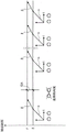
图1示出了一种现有的铁路制动系统的可能但并非唯一的体系结构。轨道制动系统产生施加到与两个车轮102结合的车轴101的制动扭矩CF100。该制动扭矩CF 100由施加到一个或多个制动缸103上的气动压力105生成,该气动压力105经由摩擦装置133直接作用在车轮102或机械地连接到车轴101的一个或多个盘(图中未示出)上。Figure 1 shows a possible, but not the only, architecture of an existing railway braking system. The rail braking system produces a braking torque CF100 that is applied to the
此外,所述制动扭矩CF 100可以由再生制动系统(也称为电动制动系统)通过使用直接或通过齿轮减速系统连接到所述车轴101的电机104生成。制动压力105由通过电子单元BCU 107控制的电动气动模块EP-模块106生成。根据电动气动图,所述电动气动模块106由电磁阀、气动阀和压力传感器组成,它们是本领域技术人员已知的现有技术的一部分。Furthermore, the
所述电子单元BCU 107控制电动气动模块106以获得对应于从减速请求110和重量值111得出的力的制动压力。重量值在每个转向架的控制中对应于转向架上的重量,或者在每个车辆的控制中对应于车辆的重量。电机104由牵引力控制108控制,从而产生从减速请求110和重量值111得出的制动扭矩。Said
根据铁路领域中被称为“混合”制动的已知方法,可以根据两个力随时间的可变百分比组成来施加摩擦和电动制动作用(electrodynamic braking contributions)。可以根据诸如电机再生效率、车辆速度、转向架重量或车辆重量的外部变量,将“混合”的百分比比例先验地映射在电子单元BCU 107和牵引力控制108的存储器中。本领域技术人员意识到存在其他可能的、非排他性的“混合”体系结构,从而通过电子单元BCU 107实时计算两个摩擦和电动制动作用的百分比比例,该电子单元BCU 107将使用图中未示出的信号直接从牵引力控制模块108请求电动制动扭矩值。According to a method known in the railway field known as "hybrid" braking, friction and electrodynamic braking contributions can be applied according to a variable percentage composition of the two forces over time. The percentage ratio of "mixed" may be mapped a priori in the memory of
如果在制动期间相对于制动扭矩CF的制动力超过了可用附着力值,例如由于雨水或树叶或轨道上的铁锈而产生劣化,则车轮102将进入打滑和潜在的锁定状态。在这种情况下,WSP(车轮防滑保护)系统109将介入。这种WSP系统109可以借助于与每个车轴(图中未示出)相关的速度传感器来检测车轮102的速度相对于车辆的速度的任何降低。在变化高于预定阈值的情况下,WSP 109可以根据本领域技术人员已知的现有技术的一部分的控制算法,通过对电磁阀113通电/断电来调制对制动缸103的压力105,以避免车轮的锁定,并将车轮维持在可控制的滑动状态,从而使抓地力的损失最小化。If the braking force relative to the braking torque CF exceeds the available adhesion value during braking, for example due to deterioration due to rain or leaves or rust on the track, the
类似地,集成到牵引力控制108中的WSP软件模块提供用于调制由电机104产生的制动扭矩,以防止车轮锁定并将车轮维持在可控制的滑动状态,从而使附着力的损失最小化。通过两个WSP之间的信号(所述信号未在图中示出)交换,根据本领域技术人员已知的策略,WSP 109和集成在牵引力控制模块108中的WSP软件模块的滑动控制动作彼此同步。Similarly, the WSP software module integrated into the
已知的物理事实是,在滑动期间,车轮102将机械能和热能以与滑动量直接而非线性地相关的量注入接触点112中。这种能量部分地清洁接触点112,提高了在车轮102的通道处留给后续车轮的附着力值。It is a known physical fact that during slip, the
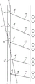
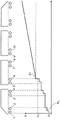
图10示出了由多个车辆组成的在劣化的附着状态下制动的铁路列车。根据给定的减速请求使列车减速所需的附着力为μn。车辆遇到的初始降低的附着力为μi<μn。为了简单起见,例如,假设所有车轮上的重量是均匀的,因此,由于共同的减速请求,所有车轮都受到相同的制动扭矩。Figure 10 shows a railway train consisting of multiple vehicles braking in a degraded adhesion state. The adhesion force required to decelerate the train according to a given deceleration request is μ n . The initial reduced adhesion encountered by the vehicle is μ i < μ n . For the sake of simplicity, for example, assume that the weight on all wheels is uniform, so all wheels experience the same braking torque due to a common deceleration request.
车轮1开始滑动阶段,该滑动阶段由WSP系统通过局部减小制动扭矩来控制。所述可控制的滑动执行部分清洁,以将附着力增加到水平μ2。针对遇到值μ<μn的所有后续车轮,滑动现象和产生的清洁以类似的方式发生,并且因此,针对车轮2,…,6,这将“释放”的附着力提高到最终值μf>μn。此时,施加到车轮7和后续车轮上的制动扭矩不会引发进一步的滑动现象。Wheel 1 begins a slip phase, which is controlled by the WSP system by locally reducing the braking torque. The controllable slide performs partial cleaning to increase adhesion to the level μ2 . The slip phenomenon and the resulting cleaning occur in a similar manner for all subsequent wheels encountering a value μ< μn , and thus, for
在现有技术中,除了所描述的动作之外,制动系统不采取进一步的动作,即通过WSP子系统的协调动作通过局部限制制动扭矩来保护车轮。明显的是,由于由WSP子系统实施的制动扭矩的局部限制,停止距离根据初始附着力μi的降低而增加。如本领域技术人员所公知的,在制动期间,即使在有足够的附着力可用于避免滑动的情况下,在车轮与轨道之间的接触点上也总是发生微滑动现象,这种现象在一定限制内继续提高可用附着力值,如仅图10中的示例所示。因此,通过将制动扭矩增加到超过列车末端处的车轮上初始计算出的值,可以部分或完全补偿前轮上已经发生的附着力损失,部分或完全恢复初始请求的减速,并且因此恢复相对制动距离。In the prior art, the braking system takes no further action than the described actions, namely to protect the wheels by locally limiting the braking torque through the coordinated action of the WSP subsystem. It is evident that the stopping distance increases according to the decrease of the initial adhesion μi due to the local limitation of the braking torque implemented by the WSP subsystem. As known to those skilled in the art, during braking, even when there is sufficient adhesion available to avoid slippage, the phenomenon of micro-slip always occurs at the point of contact between the wheel and the track, a phenomenon known as Continue to increase the available adhesion value within certain limits, as shown in the example in Figure 10 only. Thus, by increasing the braking torque beyond the initially calculated value on the wheels at the end of the train, it is possible to partially or fully compensate for the loss of adhesion that has occurred on the front wheels, partially or fully restore the initially requested deceleration, and thus restore the relative Braking distance.
例如,专利EP2648949要求保护一种在附着力下降的情况下和在紧急制动期间的附着力恢复方法,该方法将车辆后部的压力升高到所要求的值以上。这种方法由集中式系统实施,该集中式系统需要一种通信装置来协调沿车辆列车的各种制动模块。然而,EP2648949中所要求保护的解决方案具有以下缺点:For example, patent EP2648949 claims a method of recovery of adhesion in the event of a drop in adhesion and during emergency braking, which raises the pressure at the rear of the vehicle above the required value. This approach is implemented by a centralized system that requires a communication device to coordinate the various braking modules along the vehicle train. However, the solution claimed in EP2648949 has the following disadvantages:
-必须有一个在模块之间传送信息的通信系统,这使制动系统的体系结构和连接到该体系结构的软件相当复杂;- There must be a communication system for transferring information between modules, which complicates the architecture of the braking system and the software connected to it;
-需要一个协调各种模块的操作的主设备;- the need for a master device that coordinates the operation of the various modules;
-这种方法由信息交换和/或主设备支持,该信息交换和/或主设备建立如何激活以及激活哪些模块来恢复减速;因此,如果单个故障影响通信网络或主设备,则有可能出现同一系统的完全损失;- This approach is supported by an information exchange and/or master that establishes how and which modules are activated to restore the slowdown; therefore, if a single failure affects the communication network or the master, there is a possibility that the same complete loss of the system;
-由于必须根据SIL≥3级的标准EN50126/EN50128/EN50129开发用于该系统的软件,因此由于通过所述标准施加的实施限制,系统和通信网络的总体复杂性和成本增加;- Since the software for this system has to be developed according to the standards EN50126/EN50128/EN50129 with SIL ≥ 3, the overall complexity and cost of the system and communication network increases due to the implementation constraints imposed by said standards;
-由于在许多列车体系结构中,用于制动系统的全局通信系统在列车级别上不可用,而仅在车辆级别上可用,因此基于模块之间的信息交换的系统可能无法在列车级别上实施所要求保护的方法。- Since, in many train architectures, the global communication system for the braking system is not available at the train level, but only at the vehicle level, systems based on information exchange between modules may not be implemented at the train level the claimed method.
发明内容SUMMARY OF THE INVENTION
因此,本发明的目的是提供一种用于至少一个铁路车辆的行车和紧急制动控制系统,该控制系统允许在附着状态劣化的情况下恢复最初损失的减速,并且还允许在制动系统由于可能的故障而以劣化的方式操作的情况下最初损失的减速。本发明要求使用多个功能模块用于完全彼此独立地控制制动系统,每个功能模块用于控制单独的制动扭矩;使用基于系统观察的算法,以正确操作而无需从属于同一系统的其他模块接收信息,无需集中控制。It is therefore an object of the present invention to provide a service and emergency braking control system for at least one railway vehicle, which control system allows recovery of initially lost deceleration in the event of a deterioration of the adhesion state, and which also allows the braking system to recover due to possible failure while operating in a degraded manner in the event of an initial loss of deceleration. The present invention requires the use of multiple functional modules for controlling the braking system completely independently of each other, each functional module for controlling an individual braking torque; the use of an algorithm based on system observations to operate correctly without the need for other systems subordinate to the same system Modules receive information without centralized control.
根据本发明的一个方面,通过用于具有权利要求1中所限定的特征的至少一个铁路车辆的行车和紧急制动控制系统来实现前述和其他目的和优点。在从属权利要求中限定了本发明的优选实施方式。According to one aspect of the present invention, the foregoing and other objects and advantages are achieved by a service and emergency braking control system for at least one railway vehicle having the features defined in claim 1 . Preferred embodiments of the invention are defined in the dependent claims.
附图说明Description of drawings
现在将描述根据本发明的用于至少一个铁路车辆的行车和紧急制动控制系统的一些优选实施方式的功能和结构特征。参考附图,其中:The functional and structural features of some preferred embodiments of a service and emergency braking control system for at least one railway vehicle according to the present invention will now be described. Referring to the attached drawings, in which:
-图1示出了可能的现有制动系统的基本功能图;- Figure 1 shows a basic functional diagram of a possible existing braking system;
-图2示出了根据本发明的用于控制车轴的制动的系统的功能图;- Figure 2 shows a functional diagram of the system for controlling the braking of an axle according to the invention;
-图3示出了根据本发明的单个制动控制模块的功能标准;- Figure 3 shows the functional criteria of a single brake control module according to the invention;
-图4示出了根据铁路车辆的速度的制动扭矩极限的行为曲线(behavior curve);- Figure 4 shows the behavior curve of the braking torque limit according to the speed of the railway vehicle;
-图5以示例的方式示出了在包括在所述行车和紧急制动控制系统中的任何制动控制模块发生故障的情况下用于根据本发明制造的至少一个铁路车辆的制动控制系统的行为;- Figure 5 shows by way of example a brake control system for at least one railway vehicle manufactured according to the invention in the event of failure of any brake control module included in said service and emergency braking control system the behavior of;
-图6以示例的方式示出了在附着力降低的情况下用于根据本发明制造的至少一个铁路车辆的制动控制系统的行为;- Figure 6 shows by way of example the behavior of a brake control system for at least one railway vehicle manufactured according to the invention in the case of reduced adhesion;
-图7示出了行车和紧急制动控制系统的第一实施方式;- Figure 7 shows a first embodiment of the service and emergency braking control system;
-图8示出了行车和紧急制动控制系统的第二实施方式;- Figure 8 shows a second embodiment of the service and emergency braking control system;
-图9示出了行车和紧急制动控制系统的第三实施方式;- Figure 9 shows a third embodiment of the service and emergency braking control system;
-图10示出了根据现有技术的在附着力降低的情况下铁路列车的行为;以及- Figure 10 shows the behaviour of a railway train with reduced adhesion according to the prior art; and
-图11示出了根据本发明的用于双车轴转向架的制动控制的系统的功能图。- Figure 11 shows a functional diagram of the system for brake control of a two-axle bogie according to the invention.
具体实施方式Detailed ways
在详细说明本发明的多个实施方式之前,应当阐明,本发明不限于将其应用于以下描述中所呈现的或在附图中示出的组件的构造细节和配置。本发明可以假设其他实施方式并且可以以基本上不同的方式实施或实现。还应当理解,用语和术语具有描述性目的,并且不应被解释为限制性的。“包括(include)”和“包括(comprise)”及其变型的使用应理解为含有在下文中陈述的元件及其等同物,以及附加元件及其等同物。Before describing in detail various embodiments of the present invention, it should be clarified that the present invention is not limited to its application to the details of construction and arrangements of components presented in the following description or illustrated in the accompanying drawings. The invention is capable of other embodiments and of being practiced or carried out in substantially different ways. It is also to be understood that the phraseology and terminology are for the purpose of description and should not be regarded as limiting. The use of "include" and "comprise" and variations thereof should be understood to encompass the elements recited below and their equivalents, as well as additional elements and their equivalents.
另外,在本说明书中,应当理解,多个连接的铁路车辆组成了铁路列车。In addition, in this specification, it should be understood that a plurality of connected railway vehicles constitute a railway train.
除非另有说明,否则在下文中将参考制动扭矩,该制动扭矩用该定义指示仅由摩擦制动力或仅由通过牵引电机生成的电动扭矩或由两个扭矩的随时间变化的百分比组成产生的扭矩。Unless otherwise stated, in the following reference will be made to the braking torque, which by this definition is indicated by the friction braking force only or by the electric torque generated only by the traction motor or by the time-varying percentage of the two torques of torque.
首先参考图2,示出了根据本发明的用于车轴的制动控制模块的功能图。Referring first to FIG. 2, a functional diagram of a brake control module for an axle in accordance with the present invention is shown.
用于至少一个铁路车辆的制动控制系统包括多个制动控制模块201。A brake control system for at least one railway vehicle includes a plurality of
每个制动控制模块201被布置为控制铁路车辆的至少一个相应的车轴并接收减速请求信号202。Each
这种减速请求信号202是所有制动控制模块201所共有的,并且被布置为指示要实现的至少一个铁路车辆的减速目标值。Such a
此外,每个制动控制模块201被布置为接收瞬时减速信号209和实现最大可用附着力的信号204,该瞬时减速信号209指示至少一个铁路车辆的瞬时减速值,该实现最大可用附着力的信号204被设置为指示实现由所述制动控制模块201控制的车轴的最大可用附着力。Furthermore, each
为了方便起见,“所实现的最大可用附着力”的定义现在被缩写为MAAA(MaximumAvailable Adhesion Achieved)。在该实施方式中,作为示例,MAAA=0应意味着当制动控制模块201没有充分使用可用于由此控制的车轴的车轮的附着力时,而MAAA=1应意味着当由模块201控制的车轴的车轮已经超过最大可用附着力时。显然,这些值仅作为示例给出,并且仍然可以使用不同的值。当WSP模块检测到相对于由制动控制模块201控制的车轴的车轮与轨道之间的滑动高于预定值时,MAAA信号204可以例如但非排他地由WSP模块生成。此外,MAAA信号204可以例如但非排他地通过基于“附着力观察器”的算法来生成,如FAIVELEYTRANSPORT ITALIA S.p.A.的意大利专利申请第102016000034535号“Procedure for thecontrol and possible recovery of the adhesion of the wheels of controlledaxles of a railway vehicle”所述。For convenience, the definition of "Maximum Available Adhesion Achieved" is now abbreviated as MAAA (Maximum Available Adhesion Achieved). In this embodiment, by way of example, MAAA=0 would mean when the
制动控制模块201还被布置为独立于任何其他制动控制模块201生成制动扭矩请求信号205。The
这种制动扭矩请求信号205应根据减速请求信号202和重量信号203来生成,该重量信号203指示作用在包括由这种制动控制模块201控制的车轴的铁路车辆的车轴或转向架或车厢上的重量。Such a brake
制动控制模块201还被布置为将所述制动扭矩请求信号205提供给与由所述制动控制模块201控制的铁路车辆的车轴相关联的制动装置207。The
制动装置207被布置为将制动扭矩请求信号205的值转换为具有确定的制动扭矩值的制动扭矩。例如,制动扭矩请求信号205的值越高,则所确定的制动扭矩值将越高,或者反之亦然。这种制动扭矩被施加到由制动控制模块201控制的车轴上,以使至少一个铁路车辆减速。通过根据第一预定扭矩梯度实现前述确定的制动扭矩值来施加制动扭矩。The
换句话说,根据预先设置在所述制动控制模块201中的预定第一减速梯度由制动装置207施加制动扭矩。In other words, the braking torque is applied by the
在本发明的当前优选实施方式中,第一减速梯度对于包括在制动系统中的所有制动控制模块201是相同的。每个制动控制模块201可以提供用于根据其自身的重量信号203将其局部转换为其自身的第一制动扭矩梯度,从而使得包括在制动系统中的所有制动控制模块201局部均匀地促进同时实现减速请求。In the presently preferred embodiment of the present invention, the first deceleration gradient is the same for all
所生成的制动扭矩值可以根据减速请求信号202和重量信号203根据已知公式F=m·a和适当的力→扭矩转换来计算。The generated braking torque value may be calculated from the
所述制动装置207可以是被布置为提供摩擦式或电动式制动力的制动装置,或者是被布置为提供摩擦式制动力的制动装置和提供电动式制动力的制动装置的组合,所述制动装置根据混合策略来管理。
如果车轮208开始滑动,则WSP模块206具有调制用于制动装置207的制动扭矩请求信号205的功能。所述WSP模块206可以是包括用于根据所确定的算法执行摩擦式制动力的调制的至少一个装置的系统,或者是用于调制电动式制动力的软件模块。在进一步可能性中,WSP模块206可以包括用于摩擦式制动力的调制系统和用于调制电动式制动力的软件模块两者。以上对应于制动装置207的组成。在本说明书中,术语“软件模块”是指包括在计算机程序中的一个或多个软件指令,该一个或多个软件指令适于例如由微处理器执行以实现预定功能或算法。If the
减速请求信号202的值也可以直接指示制动扭矩请求值。在这种情况下,制动控制模块201可以使用公式a=F/m来确定目标减速值。另外,如果制动装置207是提供摩擦式制动力的装置,则减速请求信号202的值可以直接指示气动制动压力请求值。The value of the
在存在减速请求时,制动控制模块201生成具有对应于所述减速请求信号202的值的值的制动扭矩请求信号205。When there is a deceleration request, the
现在参考图3,假设所述减速请求需要可用附着力μ=A。如果可用附着力较低,例如由曲线μ1表示,则一旦超过峰值P1,由制动控制模块201控制的车轴就开始滑动,输入MAAA204立即假设值MAAA=1,然而制动控制模块201继续增加所请求的制动扭矩直到对应于线A的值,即直到先前计算出的对应于减速请求信号202的值及其自身重量信号203的制动扭矩被完全施加为止。WSP模块206的任务是限制由制动扭矩请求信号205请求的制动扭矩,以将车轮208的滑动维持在可控制的速度值,最终在必要时部分或全部清洁轨道并增加用于后续车轮的附着力。Referring now to FIG. 3 , assume that the deceleration request requires available adhesion μ=A. If the available adhesion is low, eg represented by curve μ 1 , once the peak value P 1 is exceeded, the axle controlled by the
该策略的原因是强制由WSP模块执行的轨道清洁动作。另一个原因是不限制可能对应于紧急制动请求的制动扭矩请求。如果可用附着力大于线A,例如由曲线μ2表示,则输入MAAA 204维持值MAAA=0,因此指示尚未实现最大可用附着力,或者仍有增加制动扭矩的空间。所述裕度对应于从线μ=A到点P2的距离。然后,制动控制模块201观察到由瞬时减速信号209指示的减速值,或者从a=F/m得出减速值,不管减速请求202是否通过在输入端处的制动扭矩或制动压力的请求而发生。The reason for this strategy is to force the orbital cleaning action performed by the WSP module. Another reason is to not limit braking torque requests that may correspond to emergency braking requests. If the available adhesion is greater than line A , eg represented by curve μ2, the
如果当从所施加的制动扭矩中获得所确定的扭矩值时,当前瞬时减速值小于目标减速值,则制动控制模块201改变制动扭矩请求信号205的值,以增加由制动装置207转换的制动扭矩。制动控制模块201改变制动扭矩请求信号205的这样的值,直到由从制动控制模块201接收到的瞬时减速信号209指示的瞬时减速值实现由减速请求信号202指示的至少一个铁路车辆的减速目标值为止,或者直到实现最大附着力可用的信号204已经指示由所述制动控制模块201控制(直接成比例转换)的车轴已经实现了最大可用附着力为止。所施加的制动扭矩依据第二预定扭矩梯度增加。If the current instantaneous deceleration value is less than the target deceleration value when the determined torque value is obtained from the applied braking torque, the
第二梯度不必与第一梯度相同。类似于第一减速梯度,在当前优选实施方式中,第二减速梯度对于包括在制动系统中的所有制动控制模块201是相同的。每个制动控制模块201根据重量信号203将其局部转换为其自身的第二制动扭矩梯度。当实现所要求的或内部计算的减速值时,附加增加结束。The second gradient need not be the same as the first gradient. Similar to the first deceleration gradient, in the presently preferred embodiment, the second deceleration gradient is the same for all
可以将对应于附着力值μ=B的制动扭矩极限值存储在制动控制模块201内。所述制动扭矩极限值是必要的,以避免由可能的可用附着力μ3使制动扭矩过度增加。制动扭矩的过度增加可能导致制动构件中的机械损坏或高温。本领域技术人员知道,随着车辆的速度增加,车轮与轨道之间的接触点处的附着力降低。为了避免由于制动扭矩的过度增加超过标称极限而触发滑动,所述制动扭矩极限值可以是速度以及重量的函数,如图4定性所示。所述函数可以具有连续的特性(实线)或具有一个或多个步骤(虚线)。The braking torque limit value corresponding to the adhesion value μ=B may be stored in the
如果可用附着力例如对应于曲线μ2,则在制动扭矩的附加增加期间,如果超过了所述附着力曲线μ2,则受控的车轴208处的滑动现象开始,输入端204假设值MAAA=1,并且制动控制模块201将制动扭矩值减小预定存储值。所述预设值可以是零等以连续地减小制动扭矩值,直到实现条件MAAA=0。预定值在任何情况下诸如都不允许所施加的制动扭矩值低于借助于减速请求信号202初始请求的制动扭矩值,该制动扭矩值对应于直线μ=A。到目前为止已经描述的是指“每个车轴”扭矩控制。图11示出了“每个转向架”的控制配置:制动控制模块1101生成制动扭矩请求1105,该制动扭矩请求1105被并行发送到与由车轮表示的两个车轴1110和1111相关联的制动扭矩生成模块1108和1109。WSP模块1106和1107与每个车轴相关联,每个WSP功能用于控制相应车轴1110和1111的滑动。If the available adhesion corresponds for example to the curve μ 2 , then if said adhesion curve μ 2 is exceeded during an additional increase in the braking torque, the slip phenomenon at the controlled
同样在这种情况下,如前所述,WSP模块1106和1107可以是系统或软件模块,或者它可以是系统和软件模块两者。Also in this case,
在图11中描述的配置中,制动控制模块1101接收与从先前描述的制动控制模块201接收的信号相同的信号。In the configuration depicted in FIG. 11 , the
此外,制动控制模块1101继续遵循先前描述的并由图2中的制动控制模块201实施的过程。在图11中描述的配置中,例如,当对应于车轮的两个车轴1110和1111都不处于滑动阶段时,MAAA信号假设值MAAA=0,并且当对应于车轮的车轴1110和1111中的至少一个处于滑动阶段时,MAAA信号假设值MAAA=1。Additionally, the
如上所述,制动控制模块201或1101完全自主地决定采取哪种动作,而无需与包括在制动系统中的一个或多个其他模块通信。As mentioned above, the
图5示出了铁路制动控制系统的行为,该铁路制动控制系统由接收减速请求的“n”个功能模块组成,并且每个功能模块具有如图11所示的每个转向架(即每对车轴)的制动扭矩控制。Figure 5 shows the behavior of a railway brake control system consisting of "n" functional modules that receive deceleration requests, and each functional module has each bogie as shown in Figure 11 (i.e. braking torque control for each pair of axles).
为了简单起见,假设在所有转向架上使用相同的重量值。因此,针对给定的减速请求,所有制动模块的制动扭矩将相同,例如,对应于线E。For simplicity, it is assumed that the same weight value is used on all bogies. Therefore, for a given deceleration request, the braking torque of all braking modules will be the same, eg, corresponding to line E.
以相同的方式,所有模块的制动扭矩增加梯度也将相同。作为示例,第二转向架被认为是有缺陷的并且不能施加所计算的制动扭矩E。有源制动控制模块1101将根据共有的梯度α将制动扭矩施加到其转向架,同时实现制动扭矩值E。此时,所述有源制动控制模块1101将观察到,由于缺乏故障转向架的制动作用,所达到的减速值低于期望的减速值。在这种情况下,所述制动控制模块1101将以彼此相等并且不必等于第一梯度的第二梯度开始增加制动扭矩,该第二梯度由角度β表示。当由每个有源模块产生的制动扭矩已经增加了值E/(n-1),即增加了等于分配给功能模块的非功能模块未提供的值时,将获得期望的减速。对应于线E的制动扭矩值以及后续对应于线F=E*n/(n-1)的值通过所有有源制动控制模块1101借助于相同的梯度α和β同时获得。在由于温度或下雨的原因,制动盘与制动垫之间的摩擦系数小于标称设计值的情况下,容易应用相同的示例。在这种情况下,所有制动控制模块1101将增加制动扭矩以补偿由盘-垫摩擦不足导致的减速的缺乏。图6示出了在附着力降低的情况下上述系统的操作情况。线G表示实现所要求的标称减速所需的制动扭矩;线H定性地表示对应于最大可用附着力的制动扭矩。线H的倾斜度表示轨道的清洁现象,以示例的方式,近似于图10中所示的μ的增加的步骤。对于铁路领域的技术人员已知的是,实际上由线H表示的事物可以以曲线的形式自然地出现,其中,线H是很好的近似,并且在任何情况下针对本演示都是足够的。在减速请求时,所有制动控制模块1101将根据第一共有梯度α施加制动扭矩G。当施加到第一转向架和第二转向架的制动扭矩值分别到达线H上的点H1和H2时,对应于第一转向架和第二转向架的车轴将开始滑动。由于发生滑动,到与第一转向架和第二转向架相关的模块的MAAA输入信号将假设MAAA=1状态。相对于第一转向架和第二转向架的制动控制模块1101将在任何情况下提供增加达到线G的制动扭矩值,与之相对应的WSP模块206将制动扭矩限制到转向架,从而将车轴保持在受控的滑动条件。如上所述,当实现制动扭矩值G时,已经接收到MAAA=1信号的与第一转向架和第二转向架相关的制动控制模块1101将永久地维持制动扭矩值G。当达到压力值“G”时,其余的制动控制模块1101观察到,由于第一转向架和第二转向架的滑动阻止了它们实现制动扭矩G,因此所实现的减速值低于期望的减速值。同时,它们将被赋予MAAA=0信号。在这种情况下,它们将以彼此相等的第二梯度β开始增加制动扭矩,第二梯度β例如但非排他地比第一梯度慢。在该示例中,在增加制动扭矩期间,第三转向架处的制动扭矩与线H相交,从而在所述第三转向架的至少一个车轴上开始滑动。此时,相应的制动控制模块1101接收到MAAA=1,并且因此,如前所述,以固定步长γ或连续降低制动扭矩,直到其接收到MAAA=0信号为止,从而中断在相应的第三转向架的车轴上的滑动,并且仍然局部获得最高可能的制动扭矩。可以决定将零值分配给参数γ。在这种情况下,制动扭矩不会降低,并且由相关的WSP模块控制,将施加永久的最小滑动,这将加速对于后续车轮的轨道清洁。In the same way, the braking torque increase gradient will also be the same for all modules. As an example, the second bogie is considered defective and cannot apply the calculated braking torque E. The active
在图6的示例中,仅第四转向架和第五转向架可以实现由线L表示的制动扭矩值,以实现所请求的减速。另一方面,如果已经编程了具有对应于图3的线B的G<J<L的制动扭矩极限值J,则相对于所述第四转向架和第五转向架的制动控制模块1101暂停制动扭矩的增加,并且没有实现期望的减速。然而,即使在劣化状态下,车辆或车辆的列车的减速总是最佳地最大化。In the example of Figure 6, only the fourth and fifth bogies can achieve the braking torque value represented by line L to achieve the requested deceleration. On the other hand, if a braking torque limit value J with G<J<L corresponding to line B of FIG. 3 has been programmed, the
容易理解所提出的系统如何涵盖复杂的情况,诸如制动系统的同时故障和低附着力状态。It is easy to understand how the proposed system covers complex situations such as simultaneous failures and low adhesion states of the braking system.
图6中所描述的例如但非排他地涉及制动控制模块201、1101的改进的变型由以下事实表示:所述制动控制模块201、1101在存在MAAA=1信号的情况下,可以借助于相应的控制信号210激活连接到其上的可能的附着力恢复装置211。附着力恢复装置211可以例如但非排他地包括电连接到该制动控制模块的一个或多个沙箱。或者,所述附着力恢复装置211可以例如但非排他地包括用于注入材料的一个或多个设备,该材料适于增加车轮与轨道之间的摩擦系数。The variant described in FIG. 6 involving, for example, but not exclusively, the improvement of the
例如,所述控制信号210可以是二进制信号,以在开/关模式下控制沙子的流动或其他附着力恢复装置211。For example, the
此外,再次以示例的方式,控制信号210可以是连续的控制信号,其被布置为根据与车辆214的速度成比例的连续定律,或者根据与和所述制动控制模块201相关联的点H与图6的线G之间的距离成比例的连续定律,或者根据与车辆214的速度以及与和所述制动控制模块201相关联的点H与图6的线G之间的距离成比例的连续定律来控制沙子的流动或其他装置用于提高附着力:。Furthermore, again by way of example, the
每个制动控制模块201还可以在达到可以存储在存储装置中的预定滑动值或可以存储在这种存储装置中的预定最小瞬时附着力值时停用所述附着力恢复装置211。Each
同样,所述制动控制模块201、1101在存在MAAA=1信号的情况下可以借助于激活和停用信号212来激活连接到其上的一个或多个磁制动蹄213,以执行轨道的清洁动作,以便增加可用附着力。另一方面,如果存在MAAA=0信号,则制动控制模块201、1101可以中断所述磁制动垫213的激活。Likewise, the
磁制动蹄的所述激活和停用信号212可以以时间波滞后发送,以避免相同控制信号的可能的连续振荡,这可能会损坏磁制动蹄213。Said activation and
上述附着力恢复装置211或磁制动蹄213的激活旨在使图6的线“H”向左移动。在这种情况下,更多的转向架可能会通过每个使用较少量的制动扭矩促进恢复所请求的减速,从而可能避免与图3的曲线μ=B相交。Activation of the
在实现可以存储在存储装置中的预定最小滑动值时或在实现可以存储在存储装置中的预定最小瞬时附着力值时,磁制动蹄213可以由制动控制模块201停用。
当实现预定制动扭矩或气动压力值时,由至少一个制动装置207生成的制动扭矩或气动压力可以被制动控制模块201中断,该预定制动扭矩或气动压力值可以存储在存储装置中。The braking torque or pneumatic pressure generated by the at least one
以下是用于控制行车和紧急制动的系统的一些示例实施方式的图示。The following are illustrations of some example implementations of systems for controlling driving and emergency braking.
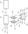
在图7所示的第一实施方式中,制动控制系统是电动气动系统。In the first embodiment shown in Figure 7, the brake control system is an electro-pneumatic system.
这种系统包括气动继动阀701,其可以由两个先导室702和703控制。在所述继动阀701的输入端705上,可以提供来自储存器(图7中未示出)的气动供应。可以在比连接到输出端704的用户所请求的压力更高的压力下提供供应。This system includes a
所述设备可以是与车轴或转向架或车辆相关的一个或多个制动缸(所述缸未在图7中示出)。The device may be one or more brake cylinders (not shown in Figure 7) associated with the axle or bogie or the vehicle.
由WSP模块104控制的阀112可以插入在继动阀701的输出端704与制动缸之间。阀701可以将对应于在控制输入端702A和703B处存在的压力值中的最高值的压力值返回到其输出端704。A
输入端702A可以由来自紧急请求(图7中未示出)的压力激励。
校准孔口711可以限制来自紧急制动请求信号202的值的压力梯度。输入端703B可以用压力707激励,所述行车制动来自通过由制动控制模块201控制的一对电磁阀708和709执行的调制作用,该制动控制模块201在该实施方式中是微处理器系统712。该调制作用是本领域技术人员已知的。在行车制动的情况下,微处理器系统712可以通过作用在阀708和709上来生成制动扭矩,从而使压力707增加,并且因此使用于气动用户的压力704增加。
以相同的方式,微处理器系统712可以通过将合适的制动扭矩请求713发送到牵引力控制系统717来生成制动扭矩,该牵引力控制系统717将控制相关的电机(未示出)。此外,微处理器系统可以生成制动扭矩,作为先前描述的气动和电动扭矩随时间变化的百分比的总和。In the same manner, the
在行车制动期间,微处理器系统712可以实施图5和图6所示的策略,首先生成制动扭矩直到图5中的水平E,即图6中具有梯度α的水平G。随后,如果条件需要,则可以生成直到图5的水平F的制动扭矩,即图6的具有梯度β的水平H。During service braking, the
在紧急制动的情况下,微处理器系统712可以在输入端703B处复制输入端702A处的瞬时压力。In the event of emergency braking, the
输入端702A处的所述压力可以具有由孔口711确定的梯度α,直到同时达到图5的水平E,即图6的水平G。Said pressure at
随后,仅微处理器系统712可以提供具有梯度β的制动扭矩的进一步增长,直到到达图5的线F,即图6的线H。Subsequently, only the
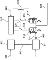
图8示出了第二实施方式,其中,行车和紧急制动控制系统是电动气动系统。Figure 8 shows a second embodiment in which the service and emergency braking control system is an electro-pneumatic system.
所述电动气动系统包括电子称重压力控制模块810,其接收重量信息813,根据该重量信息813,所述称重压力控制模块810借助于控制信号812控制电动气动模块811,使得所述电动气动模块811生成等于对应于所述重量813的紧急制动压力的气动压力814。The electro-pneumatic system comprises an electronic weighing
在该实施方式中,制动控制模块201是电子模块815,其可以经由控制信号818和819分别控制填充电磁阀816和排空电磁阀817。In this embodiment,
所述信号818和819可以被由紧急回路821激励的继电器的触点820中断。可以在没有来自紧急回路821的信号的情况下,即在没有断言的紧急制动请求的情况下示出所述触点820。当紧急请求没有被断言时,即存在来自紧急回路821的电信号时,触点820闭合,并且电子模块815可以主动控制填充816和排空817、816阀,从而产生与用于继动阀801的输入端803的制动请求823成比例的先导压力822。Said signals 818 and 819 can be interrupted by the
所述先导压力822可以将等价于紧急制动压力的压力值814假设为最大值。继动阀801可以在其输入端803处接收供应压力804,并且可以在其输出端802处为制动缸(图8中未示出)生成制动压力805。The
所述制动压力805可以具有等于先导压力822的值的值,但是具有适合于制动缸的容积的流速。在断言的紧急制动请求的情况下,假设图8所示的条件,来自紧急回路821的信号可以断电,触点820可以打开,并且电磁阀816和817可以断电。由此,紧急制动压力814可以通过由校准孔口806建立的梯度被带回到继动阀801的输入端822。继动阀801可以在其输出端802处提供等于紧急制动压力814的压力805,以激励制动缸(未示出)。Said
电子模块815可以执行图5和图6所示的策略,生成直到图5的水平E,即图6的具有梯度α的水平G的制动扭矩。The
随后,如果请求进一步增加直到图5的线F,即直到图6的线H,则电子模块815可以配置电磁阀816和817,如图8所示,即以这种方式使得将紧急制动压力814永久地带回到继动阀801的输入端822。Then, if the request increases further up to line F of FIG. 5 , ie up to line H of FIG. 6 , the
称重压力控制模块810可以根据梯度β控制模块811以提供压力的增加。所述压力是达到图5的线F,即图6的线H所必需的。The weighing
在紧急制动期间,假设图8中所示的条件,来自紧急回路821的信号可以断电,触点820打开,电磁阀816和817断电,由此紧急制动压力814可以通过由校准孔口806建立的梯度被带回到继动阀801的输入端822。孔口根据梯度α来校准。During emergency braking, assuming the conditions shown in FIG. 8, the signal from the
随后,电子称重压力控制模块810可以根据梯度β控制模块811增加压力,所述压力是达到图5的线F,即图6的线H所必需的。Subsequently, the electronic weighing
图9示出了第三实施方式,其中,行车和紧急制动控制系统是电动气动系统。Figure 9 shows a third embodiment in which the service and emergency braking control system is an electro-pneumatic system.
这种电动气动系统包括电子称重压力控制模块910,其接收重量信息913,根据该重量信息913,所述称重压力控制模块910可以借助于控制信号912控制电动气动模块911。所述电动气动模块911可以以这种方式被控制,使得所述电动气动模块911生成等于对应于所述重量913的紧急制动压力的气动压力914。This electro-pneumatic system comprises an electronic weighing
在该实施方式中,制动控制模块201是电子模块915,其可以经由控制信号918和919分别控制填充电磁阀916和排空电磁阀917,所述控制信号918和919被由紧急回路921激励的继电器的触点920中断。In this embodiment,
在没有来自紧急回路921的信号,即断言的紧急制动请求的情况下示出了所述触点920。当紧急请求没有被断言时,即存在来自紧急回路921的电信号时,触点920闭合,并且电子模块915可以主动控制阀916和917,从而产生与制动请求923成比例的制动压力922,所述制动压力922被发送到制动缸(未在图9中示出)。在断言的紧急制动请求的情况下,假设图9所示的条件,线921断电,触点920打开,电磁阀916和917断电,由此紧急制动压力914通过由校准孔口906建立的梯度返回到制动缸。The
在行车制动期间,电子模块915可以执行图5和图6所示的策略,生成直到图5的水平E,即图6的具有梯度α的水平G的制动扭矩。During service braking, the
随后,如果请求进一步增加直到图5的线F,即直到图6的线H,则电子模块915将配置电磁阀916和917,如图9所示,即以这种方式使得将压力914永久地返回到制动缸。Then, if the request increases further up to line F of FIG. 5, ie up to line H of FIG. 6, the
称重压力控制模块910可以根据梯度β控制模块911提供压力的增加。所述压力是达到图5的线F,即图6的线H所必需的。在紧急制动请求期间,假设图9中所示的条件,线921断电,触点920打开,电磁阀916和917断电,由此紧急制动压力914通过由校准孔口906建立的梯度返回到制动缸。所述孔口可以根据梯度α来校准。随后,称重压力控制模块910可以根据梯度β控制电动气动模块911以提供压力的增加。所述压力是达到图5的线F,即图6的线H所必需的。The weighing
已经描述了根据本发明的行车和紧急制动控制系统的各个方面和实施方式。应当理解,每个实施方式可以与任何其他实施方式结合。此外,本发明不限于所描述的实施方式,而是可以在由所附权利要求书限定的范围内变化。Various aspects and embodiments of the service and emergency braking control system according to the present invention have been described. It should be understood that each embodiment may be combined with any other embodiment. Furthermore, the invention is not limited to the described embodiments, but may vary within the scope defined by the appended claims.
Claims (13)
Applications Claiming Priority (3)
| Application Number | Priority Date | Filing Date | Title |
|---|---|---|---|
| IT102017000102369 | 2017-09-13 | ||
| IT102017000102369A IT201700102369A1 (en) | 2017-09-13 | 2017-09-13 | Service and emergency braking control system for at least one railway vehicle. |
| PCT/IB2018/056951 WO2019053599A1 (en) | 2017-09-13 | 2018-09-12 | Service and emergency braking control system for at least one railway vehicle |
Publications (2)
| Publication Number | Publication Date |
|---|---|
| CN111417552A CN111417552A (en) | 2020-07-14 |
| CN111417552B true CN111417552B (en) | 2022-06-28 |
Family
ID=61006125
Family Applications (1)
| Application Number | Title | Priority Date | Filing Date |
|---|---|---|---|
| CN201880059281.4A Active CN111417552B (en) | 2017-09-13 | 2018-09-12 | Service and emergency braking control systems for at least one railway vehicle |
Country Status (9)
| Country | Link |
|---|---|
| US (1) | US11654876B2 (en) |
| EP (1) | EP3681772B1 (en) |
| JP (1) | JP7387586B2 (en) |
| CN (1) | CN111417552B (en) |
| ES (1) | ES2904982T3 (en) |
| HU (1) | HUE057775T2 (en) |
| IT (1) | IT201700102369A1 (en) |
| RU (1) | RU2766466C2 (en) |
| WO (1) | WO2019053599A1 (en) |
Families Citing this family (10)
| Publication number | Priority date | Publication date | Assignee | Title |
|---|---|---|---|---|
| IT201700102369A1 (en) | 2017-09-13 | 2019-03-13 | Faiveley Transport Italia Spa | Service and emergency braking control system for at least one railway vehicle. |
| EA202192562A1 (en) * | 2019-04-30 | 2022-03-01 | Файвеле Транспорт Италиа С.П.А. | ROTATION CONTROL SYSTEM ON AT LEAST ONE AXLE FOR A RAILWAY VEHICLE OR TRAIN |
| US12162520B2 (en) * | 2020-05-29 | 2024-12-10 | Mitsubishi Electric Corporation | Electric vehicle control device, train control system, and ground device |
| CN112519736B (en) * | 2020-11-25 | 2021-12-14 | 湖北三环智能科技有限公司 | Intelligent braking method and system for heavy-load intelligent transport vehicle |
| JP7606356B2 (en) * | 2021-02-02 | 2024-12-25 | ナブテスコ株式会社 | Brake control device for railroad vehicles, Brake device for railroad vehicles |
| CN115214592B (en) * | 2022-07-13 | 2024-05-10 | 北京主导时代科技有限公司 | Rail vehicle brake detection device |
| DE102022119956A1 (en) | 2022-08-09 | 2024-02-15 | Knorr-Bremse Systeme für Schienenfahrzeuge GmbH | Control of rail vehicle parameters with local controllers |
| WO2024049838A1 (en) * | 2022-08-31 | 2024-03-07 | Tesla, Inc. | Brake temperature based speed-controlling |
| CN116080613B (en) * | 2023-04-13 | 2023-06-16 | 成都壹为新能源汽车有限公司 | Locomotive standby emergency braking system |
| WO2025012846A1 (en) * | 2023-07-11 | 2025-01-16 | Faiveley Transport Italia S.P.A. | Calibration method of a braking system of at least one vehicle, calibration system, braking system and vehicle |
Citations (7)
| Publication number | Priority date | Publication date | Assignee | Title |
|---|---|---|---|---|
| US4936610A (en) * | 1989-03-15 | 1990-06-26 | Tranergy Corporation | Differential creepage control system for optimizing adhesion of locomotives |
| US5775228A (en) * | 1997-04-14 | 1998-07-07 | General Motors Corporation | Locomotive adhesion enhancing slipping discs |
| EP1473485A2 (en) * | 2003-04-04 | 2004-11-03 | Bombardier Transportation GmbH | Reducing counter-phase vibrations |
| CN101213104A (en) * | 2005-06-30 | 2008-07-02 | 通用电气公司 | Systems and methods for locomotive attachment control |
| CN103140395A (en) * | 2010-10-01 | 2013-06-05 | 大陆-特韦斯贸易合伙股份公司及两合公司 | Method for controlling a motor vehicle brake system |
| CN103249615A (en) * | 2010-12-08 | 2013-08-14 | 克诺尔-布里姆斯轨道车辆系统有限公司 | Method for controlling an antiskid-regulated friction brake system of a rail vehicle |
| WO2017109690A1 (en) * | 2015-12-22 | 2017-06-29 | Faiveley Transport Italia S.P.A. | Method for controlling and recovering the adhesion of the wheels of a controlled axle of a railway vehicle |
Family Cites Families (19)
| Publication number | Priority date | Publication date | Assignee | Title |
|---|---|---|---|---|
| JPS506928B1 (en) | 1970-04-17 | 1975-03-19 | ||
| JPH0565065A (en) | 1991-09-09 | 1993-03-19 | Railway Technical Res Inst | Adhesiveness increasing device for rolling stock |
| US5551765A (en) | 1995-06-22 | 1996-09-03 | Westinghouse Air Brake Company | Electric brake control system and method for railroad car |
| US5820226A (en) * | 1996-02-06 | 1998-10-13 | Westinghouse Air Brake Company | Freight brake control for uniform car deceleration |
| JPH1044964A (en) | 1996-08-06 | 1998-02-17 | Nabco Ltd | Brake device for rolling stock |
| ATE374138T1 (en) | 1998-10-23 | 2007-10-15 | Knorr Bremse Systeme | BRAKE SYSTEM FOR A RAIL VEHICLE |
| DK1181179T3 (en) | 1999-05-19 | 2006-04-10 | Aea Technology Plc | Increase of wheel / rail adhesion |
| DE10128897C1 (en) | 2001-06-15 | 2003-01-02 | Knorr Bremse Systeme | Braking system for rail vehicles |
| JP2003160043A (en) | 2001-11-22 | 2003-06-03 | Nabco Ltd | Brake device for rolling stock |
| US6893058B2 (en) * | 2002-10-18 | 2005-05-17 | General Electric Company | Railway train friction management and control system and method |
| GB2402983B (en) | 2003-06-18 | 2006-07-19 | Westinghouse Brakes | Digital databus |
| WO2006000560A1 (en) * | 2004-06-24 | 2006-01-05 | Continental Teves Ag & Co. Ohg | Method for controlling the braking system of a four-wheel drive motor vehicle |
| US20080000381A1 (en) * | 2006-05-24 | 2008-01-03 | Bartley Thomas L | Rail car braking regeneration and propulsion system and method |
| DE102009042965A1 (en) | 2009-09-23 | 2011-03-24 | Siemens Aktiengesellschaft | Braking system with intelligent actuator for braking a rail-mounted vehicle |
| JP5484215B2 (en) | 2010-06-25 | 2014-05-07 | 国立大学法人長岡技術科学大学 | Train control device having train monitor / data transmission system |
| DE102011052545B4 (en) | 2011-08-10 | 2013-04-11 | Bombardier Transportation Gmbh | Brake control for a vehicle |
| US20150291138A1 (en) | 2014-04-14 | 2015-10-15 | Ford Global Technologies, Llc | Increased vehicle braking gradient |
| JP6539455B2 (en) | 2015-02-10 | 2019-07-03 | ナブテスコ株式会社 | Brake control device and brake control method |
| IT201700102369A1 (en) | 2017-09-13 | 2019-03-13 | Faiveley Transport Italia Spa | Service and emergency braking control system for at least one railway vehicle. |
-
2017
- 2017-09-13 IT IT102017000102369A patent/IT201700102369A1/en unknown
-
2018
- 2018-09-12 EP EP18783575.6A patent/EP3681772B1/en active Active
- 2018-09-12 ES ES18783575T patent/ES2904982T3/en active Active
- 2018-09-12 HU HUE18783575A patent/HUE057775T2/en unknown
- 2018-09-12 US US16/646,413 patent/US11654876B2/en active Active
- 2018-09-12 RU RU2020111085A patent/RU2766466C2/en active
- 2018-09-12 WO PCT/IB2018/056951 patent/WO2019053599A1/en not_active Ceased
- 2018-09-12 CN CN201880059281.4A patent/CN111417552B/en active Active
- 2018-09-12 JP JP2020514272A patent/JP7387586B2/en active Active
Patent Citations (7)
| Publication number | Priority date | Publication date | Assignee | Title |
|---|---|---|---|---|
| US4936610A (en) * | 1989-03-15 | 1990-06-26 | Tranergy Corporation | Differential creepage control system for optimizing adhesion of locomotives |
| US5775228A (en) * | 1997-04-14 | 1998-07-07 | General Motors Corporation | Locomotive adhesion enhancing slipping discs |
| EP1473485A2 (en) * | 2003-04-04 | 2004-11-03 | Bombardier Transportation GmbH | Reducing counter-phase vibrations |
| CN101213104A (en) * | 2005-06-30 | 2008-07-02 | 通用电气公司 | Systems and methods for locomotive attachment control |
| CN103140395A (en) * | 2010-10-01 | 2013-06-05 | 大陆-特韦斯贸易合伙股份公司及两合公司 | Method for controlling a motor vehicle brake system |
| CN103249615A (en) * | 2010-12-08 | 2013-08-14 | 克诺尔-布里姆斯轨道车辆系统有限公司 | Method for controlling an antiskid-regulated friction brake system of a rail vehicle |
| WO2017109690A1 (en) * | 2015-12-22 | 2017-06-29 | Faiveley Transport Italia S.P.A. | Method for controlling and recovering the adhesion of the wheels of a controlled axle of a railway vehicle |
Also Published As
| Publication number | Publication date |
|---|---|
| IT201700102369A1 (en) | 2019-03-13 |
| JP7387586B2 (en) | 2023-11-28 |
| WO2019053599A1 (en) | 2019-03-21 |
| RU2020111085A3 (en) | 2021-11-25 |
| CN111417552A (en) | 2020-07-14 |
| HUE057775T2 (en) | 2022-06-28 |
| RU2766466C2 (en) | 2022-03-15 |
| US20200269823A1 (en) | 2020-08-27 |
| EP3681772A1 (en) | 2020-07-22 |
| JP2020533228A (en) | 2020-11-19 |
| RU2020111085A (en) | 2021-10-13 |
| US11654876B2 (en) | 2023-05-23 |
| EP3681772B1 (en) | 2021-11-10 |
| ES2904982T3 (en) | 2022-04-06 |
Similar Documents
| Publication | Publication Date | Title |
|---|---|---|
| CN111417552B (en) | Service and emergency braking control systems for at least one railway vehicle | |
| JP7164610B2 (en) | Service and emergency brake control system for at least one rail vehicle | |
| AU2014268660B2 (en) | Thermally optimized railway vehicle brake system | |
| JP7728280B2 (en) | Electromechanical service and emergency brake actuators for rail vehicles and electromechanical braking systems | |
| WO2010056844A1 (en) | Service brake control system for optimized regenerative braking of medium or heavy trucks | |
| CN103732461A (en) | Brake system having an electromagnetic track brake device | |
| EP1569815A1 (en) | Braking system and braking control method | |
| CN107580573A (en) | For running the method and equipment of commercial car parking braking system | |
| CN115515830A (en) | Electromechanical brake system | |
| CN114981136A (en) | Method for controlling a vehicle braking system | |
| JP2016119738A (en) | Vehicular braking force control device | |
| JP2022531586A (en) | Rotation monitoring system for at least one axle for rail vehicles or trains | |
| KR20090132135A (en) | Balance Unit Braking System for Railway Vehicles | |
| CN117177888A (en) | Anti-skid system for electromechanical braking system | |
| KR20220108103A (en) | Braking system to perform additional safe braking functions |
Legal Events
| Date | Code | Title | Description |
|---|---|---|---|
| PB01 | Publication | ||
| PB01 | Publication | ||
| SE01 | Entry into force of request for substantive examination | ||
| SE01 | Entry into force of request for substantive examination | ||
| GR01 | Patent grant | ||
| GR01 | Patent grant |