CN111405722A - Light modulator - Google Patents
Light modulator Download PDFInfo
- Publication number
- CN111405722A CN111405722A CN201911301150.5A CN201911301150A CN111405722A CN 111405722 A CN111405722 A CN 111405722A CN 201911301150 A CN201911301150 A CN 201911301150A CN 111405722 A CN111405722 A CN 111405722A
- Authority
- CN
- China
- Prior art keywords
- dimmer
- channel
- control device
- channels
- dkn
- Prior art date
- Legal status (The legal status is an assumption and is not a legal conclusion. Google has not performed a legal analysis and makes no representation as to the accuracy of the status listed.)
- Pending
Links
Images


Classifications
-
- H—ELECTRICITY
- H05—ELECTRIC TECHNIQUES NOT OTHERWISE PROVIDED FOR
- H05B—ELECTRIC HEATING; ELECTRIC LIGHT SOURCES NOT OTHERWISE PROVIDED FOR; CIRCUIT ARRANGEMENTS FOR ELECTRIC LIGHT SOURCES, IN GENERAL
- H05B45/00—Circuit arrangements for operating light-emitting diodes [LED]
- H05B45/30—Driver circuits
- H05B45/31—Phase-control circuits
-
- H—ELECTRICITY
- H05—ELECTRIC TECHNIQUES NOT OTHERWISE PROVIDED FOR
- H05B—ELECTRIC HEATING; ELECTRIC LIGHT SOURCES NOT OTHERWISE PROVIDED FOR; CIRCUIT ARRANGEMENTS FOR ELECTRIC LIGHT SOURCES, IN GENERAL
- H05B45/00—Circuit arrangements for operating light-emitting diodes [LED]
- H05B45/10—Controlling the intensity of the light
- H05B45/14—Controlling the intensity of the light using electrical feedback from LEDs or from LED modules
Abstract
The invention relates to a method for identifying the correct wiring of at least two parallel electrically isolated dimmer channels of a dimmer (in particular a universal dimmer) and a correspondingly arranged dimmer, wherein for each dimmer channel information about the zero-crossing time point of the sinusoidal alternating voltage of the conductor connected thereto and information about the zero-crossings of the parallel adjacent channels is provided; and wherein the presence or absence of a significant phase shift is determined by measuring the phase shift of the two voltages, wherein the identified phase shift is indicative of a faulty wiring.
Description
Technical Field
The present invention relates to a dimmer, i.e. a device for controlling the electrical power consumption of an electrical load, in particular an integrated or connectable lighting device. Dimmers are generally known and used to vary the electrical power. The invention also relates to a method for identifying the correct wiring of at least two parallel electrically isolated dimmer channels of a dimmer.
Background
The power variation using the dimmer may preferably be achieved by leading edge phase control or by trailing edge phase control. In leading edge phase control, the current is turned on with a delay after the ac voltage zero crossing and flows to the next current zero crossing. Leading edge phase control is preferred in the case of inductive load response. Whereas in trailing edge phase control the current is switched on immediately after the zero crossing and switched off again before the next zero crossing. Trailing edge phase control is preferred in the case of capacitive load response. To generate the control commands required for its switching components, the dimmer has a main control device.
More particularly, the present invention relates to so-called multi-channel dimmers. The multi-channel dimmer has a plurality of individual dimmers, each of which individually controls a portion of the electrical load. To increase the power, these so-called dimmer channels can be connected in parallel, in series or in a hybrid manner on the output side. A plurality of physical channels are interconnected and an efficient logical channel is obtained. The dimmer channel can be located in one device or also in a plurality of devices.
However, it is important that the output of the dimmer channels is largely synchronous, precisely because of this interconnection. For example, if two channels are connected in parallel and the second channel is switched on either late (leading edge phase) or early (trailing edge phase), the first channel appears to be more overloaded than if the two channels were switched erroneously in synchronization. This may cause the first dimmer channel to overheat or fail, or even cause the dimmer to disconnect.
In the known multi-channel dimmer, each dimmer channel has its own channel control device (advantageously a simple processor) and a measuring device for measuring the electricity in the channel, which measuring device may also be formed in part by the processor. By means of the measuring device, the channel control device obtains the information required for identifying the leading edge phase or the trailing edge phase with respect to the electrical periodic behavior in the channel. The control commands generated by the main control device are each transmitted via a communication connection to the channel control device of the dimmer channel and are implemented in situ in accordance with information about the electrical periodic behavior in the channel.
The complexity of the measuring device leads in particular to high development and production costs. Zero-crossing identification inaccuracies may also result due to component tolerances or due to component aging. The resulting time difference then leads to asynchronous switching of the dimmer channel and to the problems described above. While it is possible to perform equipment replacement or recalibration of its components, this is not without cost and may result in collateral losses due to operational disturbances.
German patent document DE102017213888B3 discloses a dimmer for controlling the power consumption of a connectable load, which dimmer has at least two dimmer channels, wherein at least one dimmer channel is configured as a measuring dimmer channel for identifying the electrical behavior. To synchronize the dimmer channels, starting from the measuring dimmer channel, the channel communication connections each lead from one dimmer channel to the next dimmer channel.
German patent document DE102016209278B3 discloses a dimmer system for controlling the power consumption of a connectable load and a method for controlling the power consumption of a connectable load in a dimmer system having a master control device and at least two slave dimmers, wherein the master control device outputs synchronization signals for synchronizing respective outputs of the slave dimmers to the respective slave dimmers via a suitable communication connection, and wherein the slave dimmers are connected in parallel so as to provide a commonly controlled output for the connectable load.
While prior art dimmers and dimmer systems are suitable for phase-synchronized switching of multiple parallel physical channels or from a dimmer, they still always require manual checking whether the parallel connection of the dimmer channels has been properly wired.
Disclosure of Invention
It is therefore an object of the present invention to provide a dimmer, in particular a multichannel dimmer, and a method for easily detecting wiring errors when connecting the channels of the dimmer.
this object is achieved by a dimmer for controlling the power consumption of a connectable load, in particular an L ED lamp, having at least two parallel electrically isolated dimmer channels, each having a channel control device, at least one of the dimmer channels being configured to measure a dimmer channel, the measuring dimmer channel comprising at least a measuring device adapted to generate information about the behavior of electricity at a certain location in the measuring dimmer channel, a main control device adapted to generate at least a control command for the dimmer channel, and a communication connection adapted to transmit at least such a control command from the main control device to the channel control device of the dimmer channel, wherein the dimmer comprises at least one channel communication connection adapted to transmit at least information about the behavior of electricity at said location in the measuring dimmer channel from at least a first dimmer channel to a second dimmer channel, and wherein the channel communication connection is adapted to transmit at least information about the behavior of electricity at said location in the measuring dimmer channel, wherein from the measuring dimmer channel communication connection each is set from one sinusoidal dimmer channel to the next dimmer channel, and wherein the respective ac dimmer channel is set to identify the corresponding time at which the dimmer channel is synchronized.
In the case of a universal dimmer having a plurality of channels, each channel can only drive a certain load (e.g., 300W). If it is desired to drive a higher load (e.g., 1000W), it is not possible to use a single channel. For this reason, multiple channels are connected in parallel and therefore collectively control a larger load. These parallel channels must therefore be controlled in parallel by internal software on the one hand and wired in parallel on the other hand. If one of these two operations is not performed, damage to the universal dimmer and the load may result. The invention ensures that the parallel dimmer channels are controlled in parallel and, on the other hand, are also correctly wired in parallel. Furthermore, an error situation of a wrong wiring of the channel is immediately recognized, so that no indirection loss occurs.
Each channel of the dimmer has information about both the zero-crossing time points of the sinusoidal alternating voltage of the conductor connected thereto and the zero-crossings of the parallel-adjacent channels. By measuring the phase shift of the two voltages it can be determined whether there is a significant phase shift (error: different conductors are connected) or no significant phase shift (no error: same conductors are connected). The invention reduces the probability of incorrect wiring or incorrect parameterization in parallel operation. In the described error scenario, the dimmer automatically identifies and reports the error (e.g., by an optical or acoustic signal, or by a corresponding error message on the dimmer display, or by a corresponding message to a central station (e.g., dispatch center)). Thus, damage to the dimmer and load caused by mis-wiring/parametrization of the parallel operation is made more difficult.
Accordingly, the dimmer according to the invention comprises at least two dimmer channels, each having a channel control device. At least one of the dimmer channels is a measurement dimmer channel in that it comprises a measurement device for measuring the electricity in the channel. Its information about the behavior of the electricity in the measurement dimmer channel is transmitted to the channel control device of the measurement dimmer channel. The dimmer further comprises: a main control device that can generate at least control commands for the dimmer channels; and a main communication connection adapted to at least transmit such control commands from the main control device to the channel control device of the dimmer channel. The dimmer further comprises at least one channel communication connection from the first dimmer channel to the second dimmer channel, preferably with an element for electrically isolating the first dimmer channel from the second dimmer channel, preferably with an optical coupler or alternatively with a converter circuit. The channel communication connection can transmit information (more precisely at least information about the electrical behavior, preferably the periodic behavior, in the measuring dimmer channel) from the measuring device or from the channel control device of the first dimmer channel to the second dimmer channel, preferably to the channel control device of the second dimmer channel. The channel communication connection is preferably also adapted to transmit information in the opposite direction.
Since a communication connection (preferably comprising an electrical isolation) is inherently required between each channel control device of the dimmer channel and the main control device of the dimmer, the channel communication connections between the channel control devices to each other, which can even replace a part of the communication connection between the channel control devices and the main control device of the dimmer, can be accommodated with little additional expenditure.
The information about measuring the periodic behavior of the electricity in the dimmer channel is preferably an explanation about the time at which the channel control device of the first dimmer channel issues this information, or preferably an explanation about the time at which at least one zero crossing of the voltage in the dimmer channel is measured. Based on the stored data, the channel control device of the second dimmer channel can generate information about the periodic behavior of the field electricity from information about the periodic behavior of the electricity in the measuring dimmer channel, with which the channel control device of the second dimmer channel can switch the electricity in the channel accurately and in synchronization with the other dimmer channels. These stored data preferably include a time value equal to an estimate of the time for processing and transmitting information from the measuring dimmer channel to the control device of the second dimmer channel. The time value is constant for each dimmer channel and may contain a value related to the time at which the measuring device generates information, transmits information over the channel communication connection, or transmits information from the measuring dimmer channel to the second dimmer channel over the channel communication connection, and processes the information in the dimmer channel. The time value may be determined for each dimmer channel, i.e. from a calibration with measurements at the dimmer or at other dimmers from the same structural family, or in a simulation by means of a computer. The data are preferably stored fixedly in the channel control device.
Since no costly processing is required for transmitting the signal over a short distance, the information about measuring the electrical periodic behavior in the dimmer channel reaches the channel control device of the second dimmer channel with a small delay, but in particular in repeated cases and despite aging of the components reaches the channel control device of the second dimmer channel with almost the same delay. It is noted that this applies even to the total transmission delay if the signal is transmitted from the initial channel control device measuring the dimmer channel via some of the channel control devices and via the channel communication connection between them. Accordingly, the first dimmer channel associated with the channel communication connection may be a different dimmer channel than the measurement dimmer channel.
In an advantageous embodiment of the invention, the channel communication connection can also transmit at least a control command from the master control device from the channel control device of the first dimmer channel to the channel control device of the second dimmer channel. Thus, the instructions relating to the switching behavior are also distributed to the plurality of dimmer channels in the same way, which makes a direct communication connection to the dimmer master control device superfluous. Although two-way communication brings advantages, this can also be done in one direction for cost reasons.
In one variant of the invention, there is at least one channel communication connection between the channel control device of the measuring dimmer channel and each of the at least two dimmer channels. Thus, the measuring dimmer channel has direct channel communication connections with the plurality of control devices of the other dimmer channels. This can be implemented as a plurality of individual channel communication connections as well, or as a single channel communication connection for bus communication or the like, whereby the telegrams are received at the destination due to the individual address or the group address.
According to an advantageous embodiment of the invention even the main control device is a channel control device.
In order to identify whether the respective points in time of the respective zero crossings of the sinusoidal alternating voltage applied on the respective dimmer channels are substantially synchronized, the dimmer is equipped with a suitable analysis unit (e.g. a microcontroller with corresponding software or firmware) for analyzing information about the electrical behavior in the dimmer channels. Advantageously, the evaluation unit is arranged or integrated in the measurement dimmer channel and/or in the main control device.
A further advantageous embodiment of the invention provides that the measuring dimmer channels are designed to detect whether the respective points in time of the respective zero crossings of the sinusoidal alternating voltage present at the respective dimmer channels are substantially synchronous. If the sinusoidal alternating voltages are substantially synchronized, synchronous switching of the dimmer channels is ensured and the correct parallel wiring of the dimmer channels is identified. To recognize this, one of the dimmer channels can be designed as a measuring dimmer channel with corresponding measuring and evaluation devices. The measuring dimmer channel is in a channel communication connection with a further parallel dimmer channel.
A further advantageous embodiment of the invention provides that each dimmer channel is provided to detect whether the respective points in time of the respective zero crossings of the sinusoidal alternating voltage present at the respective dimmer channel are substantially synchronized. If the sinusoidal alternating voltages are substantially synchronized, synchronous switching of the dimmer channels is ensured and the correct parallel wiring of the dimmer channels is identified. To recognize this, each parallel dimmer channel can be designed as a measuring dimmer channel with corresponding measuring means and analyzing means.
Another advantageous embodiment of the invention provides that each dimmer channel is configured as a measuring dimmer channel having a respective measuring device and a respective communication connection to the main control device, wherein the main control device is arranged to recognize whether the respective points in time of the respective zero crossings of the sinusoidal alternating voltage applied to the respective dimmer channel are substantially synchronized. Based on the information provided by the dimmer channels about the respective periodic behavior of the electricity there, the main control device identifies whether there is a synchronous switching of the dimmer channels and a correct parallel wiring of the dimmer channels. For this purpose, the main control device is equipped with corresponding evaluation means (e.g. means for comparing the provided information), for example a microprocessor with corresponding software or firmware.
another advantageous embodiment of the invention consists in the presence of a corresponding indicator (red L ED, beeping, message output on a display, etc.) at the dimmer as to whether the respective points in time of the respective zero crossings of the sinusoidal alternating voltage applied on the respective dimmer channels are synchronized, whereby errors or disturbances in the connection of the dimmer are immediately communicated to the user (e.g. the installer).
the object is furthermore achieved by a dimmer for controlling the power consumption of a connectable load, in particular an L ED lamp, having at least two parallel, electrically isolated dimmer channels, each having a channel control device, wherein each dimmer channel is configured to measure a dimmer channel, each having a measuring device adapted at least for the identification of a zero crossing of a current and/or a voltage applied to the respective dimmer channel, a main control device which is arranged to obtain information from the respective channel control device via a suitable communication connection about a zero crossing of a sinusoidal alternating current and/or an alternating voltage applied to the respective dimmer channel and which is additionally arranged to compare the information about the zero crossing of the respective dimmer channel with one another and which is additionally arranged to generate a control command for the dimmer channels, wherein the control command can be transmitted from the main control device to the channel control devices of the dimmer channels via a suitable communication connection, wherein the main control device is arranged to identify whether zero crossings of the assigned dimmer channels for parallel operation are substantially synchronized or not.
A further advantageous embodiment of the invention provides that the main control device in the dimmer is configured as a separate component (for example as a microcontroller). In this embodiment, the channel control unit or the channel control device can be configured very inexpensively (lean), for example. This embodiment enables simple command communication and simple voltage supply of the main control unit and the channel control unit.
A further advantageous embodiment of the invention provides that the main control device is integrated into a correspondingly provided channel control device of the dimmer channel. In this embodiment, the microcontroller can be omitted. Furthermore, this design enables direct and therefore fast communication between the dimmer channels.
A further advantageous embodiment of the invention provides that the channel control device of the dimmer channel is configured as a master control device. In this embodiment, the channel control devices of the dimmer channels are substantially identical. A negotiation is made which channel control device is the master (e.g. depending on the production number or ID number). Advantageously, the determination of the master device is made automatically at start-up or at firmware loading.
A further advantageous embodiment of the invention provides that the identification of whether the respective zero crossings of the sinusoidal alternating current and/or the alternating voltage present on the respective dimmer channel are substantially synchronous is carried out by comparing the respective points in time of the zero crossings or by comparing the respective phase angles. Advantageously, this is done by measuring the time difference between zero crossings. For example, in a 50Hz system, there is a time difference of about 6.67ms between the two phases of a three-phase ac power system, which corresponds to a 120 degree phase angle. For example, in a 60Hz system, there is a time difference of about 5.55 ms.
a further advantageous embodiment of the invention provides that, upon detection of an asynchronous respective time point of the respective zero crossing of the sinusoidal ac current and/or the ac voltage applied to the respective dimmer channel, a corresponding indicator (red L ED, beeping, message output on the display, etc.) can be activated at the dimmer, for example, a safety message can be output if the measured time difference or the measured phase angle deviates from the above-mentioned value by +/-5%.
The object is also achieved by a method for identifying the correct wiring of at least two parallel electrically isolated dimmer channels of a dimmer (in particular a universal dimmer),
Wherein for each dimmer channel information about the zero-crossing time point of the sinusoidal alternating voltage of the conductor connected thereto and information about the zero-crossings of the parallel neighboring channels is provided;
Wherein it is established whether there is a significant phase shift by measuring the phase shift of the two voltages, wherein the identified phase shift represents a faulty wiring. The method may be performed, for example, at the start of a dimmer. The method is advantageously performed automatically (or forcibly) at dimmer start-up as a quality assurance measure.
Drawings
The invention and advantageous embodiments of the invention are explained by way of example with reference to the following figures.
Here:
Figure 1 shows a functional breakdown of a first example multi-channel dimmer,
Figure 2 shows a functional breakdown of a second example multi-channel dimmer,
Figure 3 shows a simplified circuit of two dimmer channels and the associated channel communication connections for the multi-channel dimmer of the second example in figure 2,
Figure 4 shows a third example multi-channel dimmer arrangement,
Figure 5 shows a fourth example multi-channel dimmer arrangement,
Figure 6 shows a fifth example multi-channel dimmer arrangement,
Figure 7 shows a sixth example multi-channel dimmer arrangement,
Figure 8 shows a seventh example multi-channel dimmer arrangement,
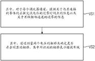
Fig. 9 illustrates an example flow chart of a method for identifying proper wiring of at least two parallel electrically isolated dimmer channels of a dimmer, particularly a universal dimmer.
Detailed Description
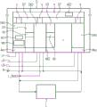
fig. 1 shows a functional breakdown of a first exemplary multichannel dimmer D on a supply network N, L1, the multichannel dimmer D having a plurality of dimmer channels K1, K2, Kx which are electrically isolated from one another and which have a channel control device S1, S2, Sx., respectively, the dimmer channels K1, K2, Kx being connected in parallel on the output side via connection terminals a1, a2, Ax to a load L, so that each can feed a portion of the current to the load L.
Dimmer D is activated by an external command B. The main control device H generates control commands which arrive via the communication connection V to the channel control device S1 of the dimmer channel K1.
The dimmer channel K1 contains a measuring device M1 which is adapted to generate information about the electrical behavior of a location in the channel, more precisely in particular about the zero crossings of the voltage. The dimmer channel K1 is therefore also referred to as a measurement dimmer channel. In operation, the communication connection transmits such information from the measurement device M1 to the channel control device S1.
Starting from the measurement dimmer channel K1, channel communication connections V12, V23, V (x-1) x each lead from one dimmer channel to the next dimmer channel. Preferably, these channel communication connections V12, V23, V (x-1) x are adapted to transmit information about the behavior of the electricity in the measured dimmer channel K1 to the channel control devices S2, Sx of the next dimmer channel K2, Kx, more precisely here from the channel control devices S1, S2 of one dimmer channel K1, K2 to the channel control devices S2, Sx of the other dimmer channel K2, Kx. These channel communication connections V12, V23, V (x-1) x can also continue to transmit control commands for the master control device H.
The communication connections V, V12, V23, V (x-1) x between the electrically isolated master control device H and the dimmer channels K1, K2, Kx contain optocouplers on both sides, respectively.
Fig. 2 shows a second example multi-channel dimmer. In the variant in fig. 2, the channel communication connections V12, V23, V (x-1) x between the dimmer channels K1, K2, Kx link the measuring device M with the respective channel control devices S1, S2, Sx for very rapid transmission. The channel communication connections V12, V23, V (x-1) x are implemented unidirectionally, so that a single communication connection V provides the control commands of the main control device H to each dimmer channel K1, K2, Kx and returns possible feedback.
Fig. 3 shows a measurement dimmer channel K1, a dimmer channel K2 and their channel communication connection V12 of a multi-channel dimmer according to the second example of fig. 2, wherein the circuits of the measurement device M1, the channel communication connection V12 and the dimmer channel K2 are shown in simplified form. The operational amplifier N11 of the measuring device M1 transforms the 230 volt network voltage into a better processed signal. The comparator N12 of the measuring device M1 performs a zero-crossing analysis on this signal. The zero crossing is passed directly to the channel control device S1, but also to the optocoupler in the channel communication connection V12. For the purpose of electrical isolation, the optocoupler contains a light emitting diode and a light sensitive resistor that switch the current through resistor R in dimmer channel K2. The optocoupler thus transmits the information about the zero crossing with little delay to the channel control device S2 and the next channel communication connection.
The measuring device M1 itself may also serve as an evaluation unit, i.e. undertake or provide evaluation functions, such as phase angle comparison and/or zero-crossing time point comparison. That is, the functions of the measuring device M1 and the analysis unit AE1 may be integrated in one component or assembly. However, the analysis function can also be implemented in a separate analysis unit AE 1.
In a further (not shown) variant of the invention, the control commands of the master control device H arrive via the unique communication connection V to the channel control device S1 of the dimmer channel K1, similar to in the variant of fig. 1. However, the channel control device S1 forwards the control command to the next dimmer channel K2 via the channel communication connection V12, as in the variant of fig. 2. To this end, however, such channel communication connections V12, V23, V (x-1) x depicted in fig. 3 are supplemented, for example, upstream of the light emitting diodes with a switch and a resistor in series with respect to ground. The switches, e.g. transistors, are switched on and off by the output of the respective channel control device Sx. When the light emitting diode is energized by the corresponding comparator Nx2, the switch may therefore apply a small voltage step on the signal, which results in a small intensity step in the light of the light emitting diode. A simple voltmeter can sense the corresponding resistance step in the photoresistor on the receiver side. However, the corresponding resistance step does not trigger zero-crossing detection there. These steps are therefore encoded by the control commands of the main control device H and forwarded to the respective channel control device Sx + 1 via the voltmeter.
In order to identify whether the respective points in time of the respective zero crossings of the sinusoidal alternating voltage applied to the respective dimmer channels K1, K2, Kx are substantially synchronized, the exemplary dimmer D according to fig. 1 or according to fig. 2 is equipped with a suitable evaluation unit AE1, AE2 (for example a microcontroller with corresponding software or firmware) for evaluating information about the electrical behavior in the dimmer channels K1, K2, Kx. The evaluation is carried out, for example, by comparing the respective points in time of the respective zero crossings of the sinusoidal ac voltage applied to the respective dimmer channel K1, K2, Kx or by evaluating the respective phase shift angle or phase difference.
Advantageously, the evaluation units AE1, AE2 are arranged or integrated in the measurement dimmer channel M1 and/or in the main control device H.
One advantageous embodiment of the invention is that each dimmer channel K1, K2, Kx is configured as a measuring dimmer channel M1, which has a respective measuring device M1 and a respective communication connection V to a main control device H, wherein the main control device H is set up to recognize whether the respective points in time of the respective zero crossings of the sinusoidal alternating voltage applied to the respective dimmer channel K1, K2, Kx are substantially synchronized. Based on the information provided by the parallel dimmer channels K1, K2, Kx about the respective periodic behavior of the electricity there, the main control device H identifies whether there is a synchronous switching of the dimmer channels K1, K2, Kx and a correct parallel wiring of the dimmer channels K1, K2, Kx. For this purpose, the main control device H is equipped with corresponding evaluation means AE2 (e.g. means for comparing the information provided), for example a microprocessor with corresponding software or firmware. In principle, each dimmer channel K1, K2, Kx can therefore have an evaluation unit AE 1.
a further advantageous embodiment of the invention consists in that corresponding indicators I (red L ED, beeping, message output on the display, etc.) are present at the dimmer D with regard to the recognition of whether the respective points in time of the respective zero crossings of the sinusoidal alternating voltage applied to the respective dimmer channels K1, K2, Kx are synchronized, whereby errors or disturbances in the connection of the dimmer D are immediately communicated to the user (e.g. the installer).
in the case of a universal dimmer having a plurality of channels DK1-DKn, each channel can only drive a certain load L A1-L An (e.g. 300W.) if it is desired to drive a higher load (e.g. 1000W.) it is not possible with a single channel for this reason that a plurality of channels DK1-DKn are connected in parallel and thus jointly control a larger load. therefore, these parallel channels 1-DKn must on the one hand be controlled in parallel by internal software and on the other hand must be wired in parallel, if one of these two operations is not performed, it may lead to damage the universal dimmer and the load. the universal dimmer D comprises a main control device H (advantageously, a suitably arranged microcontroller) which is at least adapted to generate control commands for the dimmer channel DKn-DKn H which can transmit control commands from the main control device H to the respective dimmer channel DK DKn via a communication connection V to the respective channel DK DKn-DKn via which the corresponding main control channel DK DKn-DKn H may also be set to identify whether the respective ac dimming channel 72 ac dimming voltage is supplied via the respective ac channel 72-DKn ac voltage measurement channel DKn H or via a corresponding ac voltage measurement channel DKn-DKn ac voltage measurement between the respective ac channel DKn ac communication connection terminals (e.g.g. DKn-DKn) to identify whether the respective ac dimming channel DKn ac voltage can be set via a corresponding ac voltage measurement signal.
although the dimmer D is a complete device, it has separate electrically isolated (GT) channels DK1-DKn (= load output) — it is of course possible to connect different phases L1, L2, L3 to these channels (e.g. L1 to channel DK1, L2 to channel DK2, etc.) so that driving the separate loads L A1, L A2, L An., respectively, each channel DK1-DKn can drive a certain maximum load (e.g. 300W).
However, from a software point of view, it is also possible to bundle two or more channels in order to jointly drive a load (for example 1000W) which is greater than the maximum load of the individual channels DK 1-DKn. If this is the case, all channels DK1-DKn must of course be connected to the same phase (see the dimmer arrangement according to fig. 5).
fig. 5 shows an arrangement of a multi-channel dimmer D of a fourth example, in which all channels DK1-DKn are connected to the same phase L1, it is thus possible to bundle two or more channels DK1-DKn from a software point of view (by way of corresponding phase or zero-crossing synchronization, for example by way of corresponding synchronization signals of the control unit H to the channels DK 1-DKn) in order to jointly drive a load L which is larger than the maximum load of the individual channels DK 1-DKn.
Whereas if a different phase is connected to a bundled channel (see the dimmer arrangement according to fig. 6), both the dimmer and the load may be damaged.
fig. 6 shows an arrangement of a multichannel dimmer D of a fifth example, where different phases L1, L2, L3 are connected to bundled channels DK1-dkn in case of the connection arrangement according to fig. 6, both the dimmer D and the load L (e.g. a lamp) may be damaged.
therefore, erroneous wiring (= different phases L1, L2, L3 are connected to the bundled channels DK 1-DKn) needs to be identified and reported.
The present invention identifies and reports such faulty wiring.
In addition to the load connections (wiring), fig. 4-6 also show the same exemplary multi-channel dimmer D, which can also be used as a universal dimmer.
in the case of a universal dimmer having multiple channels DKA-DKx, each channel can only drive a certain load (e.g., 300W.) if it is desired to drive a higher load (e.g., 1000W), it is not possible to use a single channel.
an exemplary dimmer D according to fig. 7 for controlling the power consumption of a connectable load L, in particular an L ED lamp, comprises:
At least two parallel dimmer channels DKa-DKx of an electrically isolated GT, the dimmer channels having channel control devices SE1-SEx, respectively, wherein each dimmer channel DKa-DKx is configured as a measuring dimmer channel having a measuring device M1, respectively, the measuring device M1 being adapted at least for identifying NDE for zero-crossings of the current and/or the respective applied voltage applied on the respective dimmer channel DKa-DKx;
A main control device H which is arranged to obtain information from the respective channel control devices SE1-SEx via a suitable communication connection V about the zero crossings ND of the sinusoidal alternating current and/or alternating voltage applied on the respective dimmer channels DKa-DKx, and which is further arranged to compare the information about the zero crossings (ND) of the respective dimmer channels DKa-DKx with each other, and which is further arranged to generate control commands for the dimmer channels DKa-DKx, wherein the control commands can be transmitted from the main control device H to the channel control devices SE1-SEx of the dimmer channels DKa-DKx via a suitable communication connection V; wherein the main control device H is arranged to identify whether the zero crossings of the assigned dimmer channels DKa-DKx are substantially synchronized for parallel operation.
In the case of the exemplary dimmer D according to fig. 7, the main control device H in the dimmer D is configured as a separate device (e.g., a microcontroller). In this embodiment, the channel control unit SE 1-SEx or the channel control device can be configured very inexpensively (lean), for example. This embodiment enables simple command communication and simple voltage supply of the main control device H and the channel control devices SE 1-SEx.
in the exemplary dimmer D according to fig. 7, the identification as to whether the respective zero crossings ND of the sinusoidal alternating current and/or the alternating voltage applied on the respective dimmer channels DKa-DKx are substantially synchronous is performed by comparing the respective points in time of the zero crossings ND or by comparing the respective phase angles in the main control device H, this is advantageously performed by measuring the time difference of the zero crossings, for example in a 50Hz system there is a time difference of about 6.67ms between the two phases of a three-phase alternating current system, which corresponds to a phase angle of 120 degrees, for example in a 60Hz system there is a time difference of about 5.55 ms.
in the case of a universal dimmer having multiple channels DKA-DKx, each channel can only drive a certain load (e.g., 300W.) if a higher load (e.g., 1000W) is desired, it is not possible to use a single channel.
an exemplary dimmer D according to fig. 8 for controlling the power consumption of a connectable load L, in particular an L ED lamp, comprises:
At least two parallel dimmer channels DKa-DKx of an electrically isolated GT, the dimmer channels having channel control devices SE1-SEx, respectively, wherein each dimmer channel DKa-DKx is configured as a measuring dimmer channel having a measuring device M1, respectively, the measuring device M1 being adapted at least for identifying NDE for zero-crossings of the current and/or the respective applied voltage applied on the respective dimmer channel DKa-DKx;
A main control device H which is arranged to obtain information from the respective channel control devices SE1-SEx via a suitable communication connection KV about the zero crossings ND of the sinusoidal alternating current and/or alternating voltage impressed on the respective dimmer channels DKa-Dkx, and which is further arranged to compare the information about the zero crossings (ND) of the respective dimmer channels DKa-DKx with each other, and which is further arranged to generate control commands for the dimmer channels DKa-DKx, wherein the control commands can be transmitted from the main control device H to the channel control devices SE1-SEx of the dimmer channels DKa-DKx via a suitable communication connection KV; wherein the main control device H is arranged to identify whether the zero crossings of the assigned dimmer channels DKa-DKx are substantially synchronized for parallel operation.
In the exemplary dimmer D according to fig. 8, the functionality of the main control device can be integrated into the correspondingly set channel control device SE1-SEx of the dimmer channel DKa-DKx. In this embodiment, the microcontroller can be omitted. Furthermore, this embodiment enables direct and therefore fast communication between the channel control devices SE1-SEx of the dimmer channels DKa-DKx.
In the exemplary dimmer D according to fig. 8, the channel control device SE 1-SEx of one of the dimmer channels DKa-DKx may be configured as a master control device, i.e. as a master. In this embodiment, the channel control devices SE 1-SEx of the dimmer channels DKa-DKx are substantially identical. A negotiation is made which channel control device SE 1-SEx is the master (main dimmer channel) (e.g. depending on the production number or ID number). Advantageously, the determination of the master device is made automatically at start-up or at firmware loading.
In the exemplary dimmer D according to fig. 8, the identification as to whether the respective zero crossings ND of the sinusoidal alternating current and/or the alternating voltage applied to the respective dimmer channels DKa-DKx are substantially synchronized is performed in the main dimmer channel by comparing the respective points in time of the zero crossings ND or by comparing the respective phase angles. In case the respective points in time of the respective zero crossings ND of the sinusoidal alternating current and/or the alternating voltage applied to the respective dimmer channels DKa-DKx are identified as not being synchronized, the respective indicator I may be activated at the dimmer D. In principle, the corresponding message can also be output to a central station within the building automation system.
Figure 9 illustrates an exemplary flow chart of a method for identifying proper wiring of at least two parallel electrically isolated dimmer channels of a dimmer (particularly a universal dimmer),
(VS 1) wherein, for each dimmer channel, information is provided about the zero-crossing time point of the sinusoidal alternating voltage of the conductor to which it is connected and about the zero-crossings of the parallel neighboring channels; and is
(VS 2) wherein it is established whether there is a significant phase shift by measuring the phase shift of the two voltages, wherein the identified phase shift is indicative of a faulty wiring.
Advantageously, the identified faulty wiring is displayed or reported by the dimmer optically (flashing lights and/or message text output on a display on the dimmer housing) and/or acoustically (e.g., a warning sound).
Damage to the dimmer D and the load (e.g. lamp) due to incorrect wiring can be avoided by the method according to fig. 9.
Each channel of the dimmer has information about both the zero-crossing time points of the sinusoidal alternating voltage of the conductor connected thereto and the zero-crossings of the parallel-adjacent channels. By measuring the phase shift of the two voltages it can be determined whether there is a significant phase shift (error: different conductors are connected) or no significant phase shift (no error: same conductors are connected).
The invention reduces the probability of incorrect wiring or incorrect parameterization in the parallel operation of the dimmers. In the described error scenario, the error is automatically identified and reported by the dimmer. Thereby, damage to the dimmer and load caused by incorrect wiring/parameterisation operating in parallel is made more difficult or even prevented.
Method and correspondingly provided dimmer for identifying the correct wiring of at least two parallel electrically isolated dimmer channels of a dimmer, in particular a universal dimmer, wherein for each dimmer channel information about the zero-crossing time point of a sinusoidal alternating voltage of a conductor connected thereto and information about the zero-crossings of parallel neighboring channels is provided; and
Wherein it is determined whether there is a significant phase shift by measuring the phase shift of the two voltages, wherein the identified phase shift is indicative of a faulty wiring.
Reference numerals
D light modulator
B command
H main control equipment
V communication connection
K1-Kx, DK 1-DKn, DKA-Dkx dimmer channels
S1-Sx, SE 1-SEx channel control equipment
M1 measuring equipment
N11 operational amplifier
N12 comparator
AE1 and AE2 analysis unit
R resistor
V12, V23, V (x-1) x, KV channel communication connection
A1-Ax, AK 1-Akn, ASK 1-ASKx connection terminal
L, L A1-Lan load
N neutral conductor
L1, L2, L3, L T outer conductor (phase)
L _ Dimm dimming load
GT electrical isolation
NDE zero crossing identification
ND zero crossing
I indicator
VS1-VS2 method steps.
Claims (22)
1. dimmer (D) for controlling the power consumption of a connectable load, in particular an L ED lamp, having:
At least two parallel electrically isolated dimmer channels (K1, K2, Kx, DK 1-DKn) each having a channel control device (S1, S2, Sx),
At least one (K1) of the dimmer channels (K1, K2, Kx, DK 1-DKn) is configured to measure a dimmer channel (K1) comprising at least a measuring device (M1) adapted to generate information about behavior of electricity at a certain location in the measuring dimmer channel;
A main control device (H) adapted to generate at least control commands for the dimmer channels (K1, 2, Kx, DK 1-DKn); and
A communication connection (V) adapted to at least transmit such control commands from the main control device (H) to the channel control device (S1) of the dimmer channel (K1),
The method is characterized in that:
The dimmer (D) comprises at least one channel communication connection (V12, V23, V (x-1) x) adapted at least to transfer information from a first dimmer channel (K1, K2) to a second dimmer channel (K2, Kx), and
The channel communication connection (V12, V23, V (x-1) x) being adapted to at least transmit information about the behavior of electricity at the location in the measurement dimmer channel (K1),
Wherein starting from the measuring dimmer channel (K1), channel communication connections (V12, V23, V (x-1) x) each lead from one dimmer channel to the next dimmer channel,
Wherein the dimmer (D) is arranged to identify whether respective points in time of respective zero-crossings of the sinusoidal alternating voltage applied on respective dimmer channels (K1, K2, Kx, DK 1-DKn) are substantially synchronized.
2. The dimmer as set forth in claim 1,
Wherein the channel communication connection (V12, V23, V (x-1) x) is adapted to at least transmit the information to a channel control device (S2, Sx) of a second dimmer channel (K2, Kx, DK 1-DKn).
3. Dimmer according to one of the preceding claims,
Wherein the information includes an explanation about a time to measure at least one zero crossing of the voltage at the location in the dimmer channel (K1).
4. Dimmer according to one of the preceding claims,
Wherein the channel control device (S2, Sx) of the second dimmer channel (K2, Kx) is adapted to generate information about the behavior of electricity at a certain location in the second dimmer channel (K2, Kx) from the information based on the stored data.
5. The dimmer as set forth in claim 4,
Wherein the data comprises a time value equal to an estimate of time for processing and transmitting the information from the measurement dimmer channel (K1) to a control device of a second dimmer channel (K2, Kx).
6. Dimmer according to one of claims 4 and 5,
Wherein the information about the electrical behavior at the location in the second dimmer channel (K2, Kx) comprises an explanation about the time of at least one zero crossing of the voltage.
7. Dimmer according to one of the preceding claims,
Wherein the channel communication connection (V12, V23, V (x-1) x) is at least also adapted to transmit control commands from the master control device (H) from the channel control device (S1, S2) of the first dimmer channel (K1, K2) to the channel control device (S2, Sx) of the second dimmer channel (K2, Kx).
8. Dimmer according to one of the preceding claims,
Wherein the channel communication connection (V1, V2, V (x-1) x) comprises an element for electrically isolating the first dimmer channel (K1, K2) from the second dimmer channel (K2, Kx).
9. Dimmer according to one of the preceding claims,
Wherein the main control device (H) is a channel control device.
10. Dimmer according to one of the preceding claims, wherein the first dimmer channel is a different dimmer channel than the measuring dimmer channel (K1).
11. Dimmer according to one of the preceding claims,
Wherein the at least two channel communication connections are adapted to transmit information about the behavior of electricity in the measurement dimmer channel (K1) from the measurement dimmer channel (K1) to at least two other dimmer channels, respectively.
12. Dimmer according to one of the preceding claims,
Wherein the measurement dimmer channel (K1) is arranged to identify whether respective points in time of respective zero-crossings of the sinusoidal alternating voltage applied on the respective dimmer channel (K1, K2, Kx, DK 1-DKn) are substantially synchronized.
13. Dimmer according to one of the preceding claims,
Wherein each dimmer channel (K1, K2, Kx, DK 1-DKn) is arranged to identify whether respective points in time of respective zero crossings of the sinusoidal alternating voltage applied on the respective dimmer channel (K1, K2, Kx, DK 1-DKn) are substantially synchronized.
14. Dimmer according to one of the preceding claims,
Wherein each dimmer channel (K1, K2, Kx, DK 1-DKn) is configured to measure a dimmer channel (K1) having a respective measuring device (M1) and a respective communication connection (V) to a main control device (H), wherein the main control device (H) is arranged to identify whether respective points in time of respective zero-crossings of the sinusoidal alternating voltage applied on the respective dimmer channel (K1, K2, Kx, DK 1-DKn) are substantially synchronized.
15. Dimmer according to one of the preceding claims, wherein the corresponding indicator (I) is activatable at the dimmer upon recognizing that the respective points in time of the respective zero crossings of the sinusoidal alternating voltage applied on the respective dimmer channel (K1, K2, Kx, DK 1-DKn) are out of sync.
16. dimmer (D) for controlling the power consumption of a connectable load (L), in particular an L ED lamp, having:
At least two parallel electrically isolated dimmer channels (DKA-DKx) each having a channel control device (SE 1-SEx), wherein each dimmer channel (DKA-DKx) is configured as a measuring dimmer channel each having a measuring device (M1) which is at least suitable for identifying a zero crossing (NDE) of a current and/or a voltage applied to the respective dimmer channel (DKA-DKx);
A main control device (H) which is arranged to obtain information about zero crossings (ND) of the sinusoidal alternating current and/or alternating voltage applied on the respective dimmer channels (DKA-DKx) from the respective channel control devices (SE 1-SEx) via a suitable communication connection (V, KV), and which is further arranged to compare the information about the zero crossings (ND) of the respective dimmer channels (DKA-DKx) with each other, and which is further arranged to generate control commands for the dimmer channels (DKA-DKx), wherein the control commands can be transmitted from the main control device (H) to the channel control devices (SE 1-SEx) of the dimmer channels (DKA-DKx) via a suitable communication connection (V, KV),
The method is characterized in that:
The main control device (H) is arranged to identify whether zero crossings of the assigned dimmer channels (DKA-DKx) are substantially synchronized for parallel operation.
17. Dimmer (D) according to claim 16,
Wherein the main control device (H) in the dimmer (D) is configured as a separate device (e.g. a microcontroller).
18. Dimmer (D) according to claim 16,
Wherein the main control device (H) is integrated into a correspondingly set channel control device (SE 1-SEx) of the dimmer channel (DKa-DKx).
19. Dimmer (D) according to claim 16,
Wherein the channel control device (SE 1-SEx) of the dimmer channel (DKA-DKx) is configured as a master control device (H).
20. Dimmer (D) according to one of claims 16 to 19,
Wherein the identification as to whether the respective zero crossings (ND) of the sinusoidal alternating current and/or the alternating voltage applied to the respective dimmer channels (DKA-DKx) are substantially synchronized is carried out by comparing the respective points in time of the zero crossings (ND) or by comparing the respective phase angles.
21. Dimmer (D) according to one of claims 16 to 20,
Wherein a corresponding indicator (I) is activatable at the dimmer (D) upon recognition of an out of synchronization of the respective points in time of the respective zero crossings (ND) of the sinusoidal alternating current and/or the alternating voltage applied on the respective dimmer channel (DKa-DKx).
22. A method for detecting the correct wiring of at least two parallel, electrically isolated dimmer channels (K1, K2, Kx, DK 1-DKn) of a dimmer, in particular a universal dimmer,
Wherein for each dimmer channel (K1, K2, Kx, DK 1-DKn) information is provided about the zero-crossing time point of the sinusoidal alternating voltage of the conductor connected thereto and about the zero-crossings of the parallel adjacent channels;
Wherein the presence or absence of a significant phase shift is determined by measuring the phase shift of the two voltages, wherein the identified phase shift is indicative of a faulty wiring.
Applications Claiming Priority (2)
| Application Number | Priority Date | Filing Date | Title |
|---|---|---|---|
| DE102018009924.6 | 2018-12-17 | ||
| DE102018009924.6A DE102018009924B4 (en) | 2018-12-17 | 2018-12-17 | Dimmer and procedure for recognizing the correct wiring of dimming channels |
Publications (1)
| Publication Number | Publication Date |
|---|---|
| CN111405722A true CN111405722A (en) | 2020-07-10 |
Family
ID=68732637
Family Applications (1)
| Application Number | Title | Priority Date | Filing Date |
|---|---|---|---|
| CN201911301150.5A Pending CN111405722A (en) | 2018-12-17 | 2019-12-17 | Light modulator |
Country Status (4)
| Country | Link |
|---|---|
| US (1) | US10743381B2 (en) |
| EP (1) | EP3672375A1 (en) |
| CN (1) | CN111405722A (en) |
| DE (1) | DE102018009924B4 (en) |
Families Citing this family (1)
| Publication number | Priority date | Publication date | Assignee | Title |
|---|---|---|---|---|
| DE102020108475A1 (en) | 2020-03-27 | 2021-09-30 | Schneider Electric Industries Sas | POWER CONTROL CIRCUIT, POWER CONTROL PROCEDURES |
Citations (5)
| Publication number | Priority date | Publication date | Assignee | Title |
|---|---|---|---|---|
| US6046550A (en) * | 1998-06-22 | 2000-04-04 | Lutron Electronics Co., Inc. | Multi-zone lighting control system |
| CN2802896Y (en) * | 2005-04-19 | 2006-08-02 | 广州大学 | Distribution type energy-saving controller for street lamp |
| CN102668703A (en) * | 2009-12-15 | 2012-09-12 | 3M创新有限公司 | Dimmer and illumination apparatus with amplitude ordered illumination of multiple strings of multiple color light emitting devices |
| EP3253182A1 (en) * | 2016-05-30 | 2017-12-06 | Siemens Schweiz AG | Dimmer system |
| DE102017213888B3 (en) * | 2017-08-09 | 2018-10-31 | Siemens Schweiz Ag | dimmer |
Family Cites Families (10)
| Publication number | Priority date | Publication date | Assignee | Title |
|---|---|---|---|---|
| US3284667A (en) * | 1963-09-09 | 1966-11-08 | Thomas Industries Inc | Dimmer control for system having master and slave dimming devices using pulse signalling therebetween |
| US7007305B2 (en) * | 2001-09-06 | 2006-02-28 | Genlyte Thomas Group Llc | Repeater amplifier with signal firewall protection for power line carrier communication networks |
| DE102006013518B3 (en) * | 2006-03-23 | 2007-09-27 | Siemens Ag | Multi-channel dimmer has multiple dimmer unit, which has control unit and power stage accessed by control unit, control unit of selected dimmer unit take check mode, in which selected dimmer unit functions as master dimmer |
| US7723925B2 (en) * | 2006-06-22 | 2010-05-25 | Lutron Electronics Co., Inc. | Multiple location dimming system |
| CA2781392C (en) * | 2009-11-20 | 2015-03-17 | Lutron Electronics Co., Inc. | Controllable-load circuit for use with a load control device |
| CN105122942B (en) * | 2013-04-03 | 2017-05-03 | 飞利浦照明控股有限公司 | Dimmer and led driver with dimming modes |
| EP2925095B1 (en) * | 2014-03-28 | 2020-09-23 | Helvar Oy Ab | A lighting controller |
| US9484814B2 (en) * | 2014-11-07 | 2016-11-01 | Power Integrations, Inc. | Power converter controller with analog controlled variable current circuit |
| WO2017185084A1 (en) * | 2016-04-22 | 2017-10-26 | Hubbell Incorporated | Devices, systems, and methods for controlling electrical fixtures |
| DE102017215643B3 (en) * | 2017-09-06 | 2018-07-26 | Siemens Schweiz Ag | Dimmer system and method for controlling the power consumption of a load connectable to a dimmer system |
-
2018
- 2018-12-17 DE DE102018009924.6A patent/DE102018009924B4/en active Active
-
2019
- 2019-11-19 EP EP19209893.7A patent/EP3672375A1/en active Pending
- 2019-12-03 US US16/701,699 patent/US10743381B2/en active Active
- 2019-12-17 CN CN201911301150.5A patent/CN111405722A/en active Pending
Patent Citations (5)
| Publication number | Priority date | Publication date | Assignee | Title |
|---|---|---|---|---|
| US6046550A (en) * | 1998-06-22 | 2000-04-04 | Lutron Electronics Co., Inc. | Multi-zone lighting control system |
| CN2802896Y (en) * | 2005-04-19 | 2006-08-02 | 广州大学 | Distribution type energy-saving controller for street lamp |
| CN102668703A (en) * | 2009-12-15 | 2012-09-12 | 3M创新有限公司 | Dimmer and illumination apparatus with amplitude ordered illumination of multiple strings of multiple color light emitting devices |
| EP3253182A1 (en) * | 2016-05-30 | 2017-12-06 | Siemens Schweiz AG | Dimmer system |
| DE102017213888B3 (en) * | 2017-08-09 | 2018-10-31 | Siemens Schweiz Ag | dimmer |
Also Published As
| Publication number | Publication date |
|---|---|
| EP3672375A1 (en) | 2020-06-24 |
| DE102018009924A1 (en) | 2020-06-18 |
| DE102018009924B4 (en) | 2020-10-01 |
| US10743381B2 (en) | 2020-08-11 |
| US20200196408A1 (en) | 2020-06-18 |
Similar Documents
| Publication | Publication Date | Title |
|---|---|---|
| JP5383924B2 (en) | Method for controlling operation of electronic converter, corresponding electronic converter, lighting system and software product | |
| EP3229561A1 (en) | Stepless dimming control method of lighting system | |
| CN110673054B (en) | DC/DC power supply test system and aging test method of DC/DC power supply | |
| CN111405722A (en) | Light modulator | |
| US5717335A (en) | Electric bulb short detection apparatus for traffic signal controller | |
| CN111279795B (en) | Multi-channel attenuator | |
| KR101362453B1 (en) | Lamp breakdown checking monitoring for lighting fixture | |
| KR101580260B1 (en) | Dimming Control System of A Couple of LED Lights | |
| US6922087B2 (en) | Control arrangement for power electronic system | |
| US10581622B2 (en) | Communication device and communication system | |
| JP3584522B2 (en) | Lighting equipment | |
| US11408921B2 (en) | Circuit and method for realizing a combined connection of neutral wires or live wires using phase information of the neutral wires and the live wires | |
| CN104808079A (en) | Method for diagnosing a frequency converter | |
| US4233598A (en) | Emergency stop circuit monitoring system | |
| EP3874693B1 (en) | System for providing a sequence of nodes in a network | |
| CN113655752B (en) | Two-bus equipment, self-checking method thereof and building automatic control system | |
| JP6221639B2 (en) | Load control device and parent device | |
| CN110861986B (en) | Elevator shaft cable detection method and device | |
| US8736248B2 (en) | Detection circuit and a method for detecting a wrong supply voltage | |
| CN109581083B (en) | Open-phase detection device of three-phase alternating current power supply and power electronic system | |
| JP2676499B2 (en) | Aviation light core detection device | |
| RU2623108C1 (en) | Method of automatic diagnostics of loads in electrical power supply network | |
| CN105021892A (en) | Intelligent device for checking phases of cables | |
| KR200465829Y1 (en) | Lamp breakdown checking monitoring device for lighting fixture | |
| CN115053142A (en) | Connection detection system, device and method for connection structure |
Legal Events
| Date | Code | Title | Description |
|---|---|---|---|
| PB01 | Publication | ||
| PB01 | Publication | ||
| SE01 | Entry into force of request for substantive examination | ||
| SE01 | Entry into force of request for substantive examination |