CN1113373C - Pressure switch - Google Patents
Pressure switch Download PDFInfo
- Publication number
- CN1113373C CN1113373C CN96105592A CN96105592A CN1113373C CN 1113373 C CN1113373 C CN 1113373C CN 96105592 A CN96105592 A CN 96105592A CN 96105592 A CN96105592 A CN 96105592A CN 1113373 C CN1113373 C CN 1113373C
- Authority
- CN
- China
- Prior art keywords
- base
- pressure
- unloader
- switch
- contact
- Prior art date
- Legal status (The legal status is an assumption and is not a legal conclusion. Google has not performed a legal analysis and makes no representation as to the accuracy of the status listed.)
- Expired - Fee Related
Links
- 239000012530 fluid Substances 0.000 claims abstract description 39
- 230000004888 barrier function Effects 0.000 claims description 24
- 230000004044 response Effects 0.000 claims description 3
- 230000009471 action Effects 0.000 abstract description 3
- 239000012528 membrane Substances 0.000 abstract 2
- 230000007246 mechanism Effects 0.000 description 12
- XLYOFNOQVPJJNP-UHFFFAOYSA-N water Substances O XLYOFNOQVPJJNP-UHFFFAOYSA-N 0.000 description 12
- 238000009434 installation Methods 0.000 description 9
- 230000006872 improvement Effects 0.000 description 7
- 238000000034 method Methods 0.000 description 7
- 238000005452 bending Methods 0.000 description 6
- 230000006835 compression Effects 0.000 description 6
- 238000007906 compression Methods 0.000 description 6
- 238000004519 manufacturing process Methods 0.000 description 6
- 230000000694 effects Effects 0.000 description 5
- 230000008569 process Effects 0.000 description 5
- 238000004458 analytical method Methods 0.000 description 4
- 238000004080 punching Methods 0.000 description 4
- 230000008859 change Effects 0.000 description 3
- 238000005516 engineering process Methods 0.000 description 3
- 230000010355 oscillation Effects 0.000 description 3
- 238000007789 sealing Methods 0.000 description 3
- 230000001154 acute effect Effects 0.000 description 2
- 238000004891 communication Methods 0.000 description 2
- 238000010276 construction Methods 0.000 description 2
- 230000005611 electricity Effects 0.000 description 2
- 238000012544 monitoring process Methods 0.000 description 2
- NJPPVKZQTLUDBO-UHFFFAOYSA-N novaluron Chemical compound C1=C(Cl)C(OC(F)(F)C(OC(F)(F)F)F)=CC=C1NC(=O)NC(=O)C1=C(F)C=CC=C1F NJPPVKZQTLUDBO-UHFFFAOYSA-N 0.000 description 2
- 238000003825 pressing Methods 0.000 description 2
- 230000001105 regulatory effect Effects 0.000 description 2
- 206010044456 Transverse presentation Diseases 0.000 description 1
- 230000003042 antagnostic effect Effects 0.000 description 1
- 238000013459 approach Methods 0.000 description 1
- 230000008901 benefit Effects 0.000 description 1
- 239000012141 concentrate Substances 0.000 description 1
- 230000008602 contraction Effects 0.000 description 1
- 238000009826 distribution Methods 0.000 description 1
- 238000005265 energy consumption Methods 0.000 description 1
- 238000002637 fluid replacement therapy Methods 0.000 description 1
- 239000011810 insulating material Substances 0.000 description 1
- 238000009413 insulation Methods 0.000 description 1
- 239000007788 liquid Substances 0.000 description 1
- 239000002184 metal Substances 0.000 description 1
- 238000012545 processing Methods 0.000 description 1
- 238000003672 processing method Methods 0.000 description 1
- 235000020681 well water Nutrition 0.000 description 1
- 239000002349 well water Substances 0.000 description 1
Images


Landscapes
- Switches Operated By Changes In Physical Conditions (AREA)
Abstract
The present invention relates to a pressure switch which comprises a base, wherein a membrane which is suitable to bear the action of the mechanical fluid pressure source is fixed on the base, and an electrical contact arranged on the base relatively moves between an open and a close positions; a lever device is arranged between the membrane and the electrical contact so that the electrical contact can relatively moves between the open and the close positions; an unloading valve connected with the pressure fluid source is arranged on the base; when the electrical contact is in the open position, the unloading valve empties the pressure fluid of the fluid source; the pressure switch also comprises a two-arm crank which responds to the lever device and controls the unloading valve; the base is provided with at least two sets of installing holes which are installed on the unloading valve and separated, and the two-arm crank is selectively installed in a relevant position near any set of the installing holes.
Description
Technical field
The present invention relates to electric switch, more precisely, relate to and be suitable for the pressure switch that links to each other with pressure fluid source, the condition of the pressure determine switch of fluid.
Background technology
In the occasion of the pressure change circuit condition that utilizes fluid, pressure switch is used widely.Once be that well-known application is on air compressor.Under these circumstances, Stirling engine usually is by a motor driven.Stirling engine sucks air from atmosphere, it is compressed to elevated pressures, then compressed air is entered in the reservoir vessel, is later use.
As everyone knows, container generally has pressure limit.In other words, surpass a certain predetermined value if be stored in the interior pressure of the fluid in the container, container may break.
In order to prevent this from occurring, compressor assembly generally has a pressure switch.When the pressure in the container reached a certain predetermined value, pressure switch was just opened, thereby opened the circuit of the motor that drives Stirling engine.Then, this means the compression of wanting the end operation circulation, and because idle compressor is no longer carried compressed air at this moment, the pressure in the container can not raise again.
When the compressed air in the use container, the compression stress in the container will reduce.Under a certain predetermined pressure, generally be lower than the above-mentioned value that opens circuit slightly, pressure switch will be closed, gives the motor energising of Stirling engine again.Then, give container transport compressed air again, up to reaching initial predetermined pressure again, at this moment, pressure switch is opened, and motor shuts down.
In the fluid system of non-gaseous fluids, can adopt similar system, for example water pump system.For example, in the general service water system of supply well water, start container or tank that immersible pump rises to water sealing.Because tank seals, the pressure of the air on the top of the water in the tank of water filling raises.When opening tap or valve, this pressure head is delivered to water distribution system with water from tank.Utilize unidirectional valve to prevent that this pressure from making water get back to well.
Usually, when water filling is arrived to a certain degree, produce pressure in the container.Modal is that with the pressure in hydraulic pressure sensitive switch monitoring tank exit, the water surface in this place's container is low.When pressure was low, the hydraulic pressure sensitive switch made pump work; When pressure rose to indication and container injected the water level of water of q.s, the hydraulic pressure sensitive switch quit work pump.
Get back to the situation of air compression system now, those of ordinary skill in the art is easy to understand certainly, when pressure switch is turned off Stirling engine, exists higher residual pressure in pipeline between from the Stirling engine to the container and the Stirling engine itself.In order to restart compressor, need be enough to overcome the so much power of resistance that residual high pressure produces.This usually needs an excessive motor to be used for starting, and having started the back at it just can Driven Compressor with a much smaller motor.Because need an excessive motor, this just means more energy consumption and drops into higher first current cost.
For fear of this thing happens, common employing a kind of so-called " off-load " valve in air compressor industry.When Stirling engine quits work, the action of unloader, with machine but be not container emptying, the interior pressure in the machine is an atmospheric pressure, is not the high pressure in the container.Therefore, when machine restarts, only frictional resistance need be overcome, less motor can be used.In the ordinary course of things, pressure switch has such structure, opens or during electric open position, they also operate this unloader when it is transformed into from closed or electric on-position.
The difficulty that the producer faced of pressure switch is that the parts of the compressor assembly that not every user is used all have same structure.That is to say that the certain user may wish that the compressor connector of unloader upwards opens, the certain user wishes that it opens to the right, and the certain user wishes that it opens left, or the like.It obviously is undesirable all making a kind of diverse pressure switch for every kind of situation, because for example make three kinds of different switches rather than a kind of switch increase cost.
Pressure switch also comprises an override with hand controller traditionally, and it is subjected to operating personnel's control, with biography be stressed switch control motor operations or stop its work.Usually, these controllers are lever-type, stretch out from a side of switch.In addition, because the structure difference of the parts of system, the producer of a system wishes that hand controller stretches out from a side of switch, and the producer of another system wishes that then this controller stretches out from the opposite side of switch.This also needs the structure difference of switch, is very non-remunerative and poor efficiencys and make two kinds of different switches for this reason.
In this class control system, also have another problem to need usually to consider, promptly may vibrate in electricity connection or the relevant each other electric contact of make position.Vibration causes too early wearing and tearing, and can cause in severe case and burn even the arcing fault.Under normal conditions, vibration is that the shake of passing to pressure switch in having the Stirling engine course of work of piston usually causes.The closed plane of contact usually is or is parallel with the base of switch, or perpendicular.The vibration-direction of the piston in the base of the system at the place of switch own and the Stirling engine is parallel or vertical.Under these circumstances, the vibration of contact is the most serious.
Those of ordinary skill in the art knows that certainly pressure switch generally has a differential pressure mechanism, and its effect is a setting pressure, and the contact of switch will disconnect under the pressure that sets, and the contact that is lower than the pressure switch that sets wants closed.Usually, set the pressure that cuts off compressor and connect compressor with this mechanism to the differential pressure between second and the lower pressure of container fluid replacement.When with the maximum pressure in the operating process of being considered serving as basis during, regulate this mechanism and can cause the pressure change that opens circuit with this mechanism setting pressure.Further require to be, recover, should regulate according to so-called " cut-in pressure " in view of the work of Stirling engine should consume the segment fluid flow in the container.Adopt this method, under the situation of high pressure that changes system never in any form or opening pressure, obtain needed differential pressure.
In addition, well-known, many pressure switches have two levers at least, structurally they pressure sensor device as a barrier film and can be disconnected or closed electric contact between.Under normal conditions, these levers structurally are to link by a mechanism of crossing the center, the contact are disconnected and closed action so that produce, and can reduce the arcing of contact like this and therefore burn out.Self-evident, pressure switch should have the suitable mechanism that these levers are installed, and they combine reliably, and in other words they are worked reliably.Although accurate technique equipment does not occur as yet because of the cost problem, need them to realize the demand of reliability to a certain extent simultaneously.Obviously, under the prerequisite of not sacrificing reliability, spendable cheap manufacturing technology equipment needs most.
Summary of the invention
The present invention will solve above-mentioned one or more problems.
Main purpose of the present invention provides a kind of new improved pressure switch.Specifically, an object of the present invention is to provide a kind of new improved pressure switch, this pressure switch has the form of multiple installation unloader, thereby makes it be fit to the different producers' system; In this pressure switch, be easy to unloader is installed on the pressure switch by an angle position in a plurality of different angles position, to be fit to arbitrary producer's special requirement; In this pressure switch, manual actuator can be installed in each side of switch, to be fit to special producing person's needs; When this pressure switch is closed, the pedestal of its contact and switch or base angulation greater than 0 ° less than 90 °, therefore, these contacts not can with the principal oscillation plane parallel of the system of setting pressure switch with vertical; This pressure switch comprises a pressure switch carriage, through punching and crooked making, and low cost of manufacture, and have the required precision of installation lever etc.
A typical embodiment of the present invention has realized above-mentioned one or more purposes with a kind of pressure switch construction.This pressure switch comprises a base, one be fixed on the base and the barrier film of the fluid source effect that is under pressure and being installed between the open and close position, do on the base mutually near and the contact that relatively moves left.This switch comprises that mechanically being installed between barrier film and the contact response acts on the leverage that pressure on the barrier film is realized the relative motion between switch contact.One unloader is installed on base, and this valve is suitable for linking to each other with pressure fluid source, when the contact is shown in an open position, and this valve events, the pressure fluid of emptying pressure fluid source.The response leverage is handled the device of unloader.
One aspect of the present invention, the special improvement of paying attention to is that base has at least two unloader erecting devices that separate, operating device selectively is installed near arbitrary erecting device.
In a kind of form of the present invention, unloader comprises that one has the valve body that is suitable for the interface channel that links to each other with pressure fluid source and one and is suitable for the control valve that moved by operating device.This control valve is contained on the switch by a plane that is pressed against on the switch pedestal, the direction of access opening roughly with plane parallel.Each erecting device comprises that all the unloader that will have a plane is installed in device on the base by the unspecified angle position in a plurality of different angles position of the interface channel relevant with base.
In a preferred embodiment of the present invention, each erecting device all comprises a hole on the base, can see through this hole and handle unloader, and a plurality of installing holes are arranged on every side in this hole.
Preferablely be, operating device comprises a both arms crank throw, and its arm can contact with leverage, and another arm can contact with off-load, and a hinging pin shaft is arranged in the middle of two arms.Base comprises two hinging pin shaft installing holes, contiguous each erecting device in each hole.
According to another aspect of the present invention, in this pressure switch, unloader has a valve body and an interface channel, and valve body has an installed surface that is pressed against on the base, the interface channel is suitable for linking to each other with pressure fluid source, and the interface channel is parallel to installed surface substantially and gets through from valve body.This pressure switch has valve body is installed in device on the base by the unspecified angle position in a plurality of different angles position of the interface channel relevant with base.
According to this embodiment of the present invention, i.e. preferred embodiment, the contiguous installed surface of base has the hole that enters of a unloader, and operating device sees through this hole and handles unloader.Erecting device is included in a plurality of holes that separate by angle around the hole that enter on the base.
In a preferred embodiment, base has two opposite sides.Every side all has one to enter the hole, and two same erecting devices are arranged, and every side has one.
Equally, in a preferred embodiment, operating device comprises a both arms crank throw, also comprise will contiguous every side the both arms crank throw be installed near the corresponding inlet port device.
According to the another aspect of this pressure switch, unloader comprises a valve body, and this valve body has a face and the side adjacent with this face, valve body can be installed on the base by this face.One straight channel stretches into valve body and form a valve seat in the middle of two ends of valve body from this face.One interface channel is arranged on the valve body, and this passage extends between away from the straight channel of that end of this face and side, and is suitable for linking to each other with pressure fluid source.A valve is arranged in the straight channel between valve seat and far-end, and this valve has one and runs through the wherein through hole of the heart.One poppet valve is arranged in central through hole, and this poppet valve has one and stretches out from centre bore and to arrive and the operating device position contacting.
Preferable is that this passage is vertical with straight channel substantially and parallel with this face.
In a preferred embodiment, stretch out installation foot from contiguous this face of valve body, base comprises a plurality of holes that separate by angle.One threaded fastener passes installation foot and enters arbitrary hole, thereby valve body is installed on the base by a plurality of different angle positions.
In a highly preferred embodiment, a plurality of installation feet are arranged on the valve body, threaded fastener can pass arbitrary installation foot valve body is installed on the base.
In one embodiment of the invention, base U-shaped normally.
According to another aspect of the present invention, a kind of pressure switch has a base; The fluid source effect that is suitable for being under pressure of a barrier film that is fixed on the base, a side of barrier film, the opposite side of barrier film is a reverse side; Rightabout along pressure fluid acts on the spring on the reverse side of barrier film and is installed in fixed contact on the base.Also have movable contact, one first lever is hinged on the base, and movable contact is contained on first lever, so that move between electricity connection and the disconnected position of TURP the relative fixed contact.One second lever is hinged on the base and with barrier film and is connected, so that co-operating.Cross central authority for one and laterally connect first and second levers.Second lever has a manual actuator.
According to the present invention, the special improvement of paying attention to of this respect is that base has two opposite sides, and every side all comprises the device that manual actuator is installed, and can selectively manual actuator be installed in either side like this.
In a preferred embodiment, erecting device comprises a pair of actuator installing hole, and an installing hole is all arranged on each side of base.
According to one aspect of the present invention, actuator comprises a cam that meshes with second lever, each installing hole all has the circular arc portion greater than 180 ℃, and to hold the axle journal of actuator, each installing hole also comprises first enlarged identical shaped with the profile of cam.
In a preferred embodiment, each hole comprises second enlarged relative substantially with first enlarged.Two stop surfaces are determined in the both sides of second portion, by contacting with any one stop surface, make actuator stop.
Preferablely be the harmonious but axially-spaced of cam and stop surface.
In a preferred embodiment, base is flat, and contact and base acutangulate.
The present invention's improvement on the other hand is that base is determined a mounting plane to switch, has two fixed contacts that separate, movable contact be stretch out and can connect with fixed contact.When the contact is in electric on-position, the folded acute angle of the projection axis of movable contact and mounting plane greater than 0 ° less than 90 °.
Preferablely be that this acute angle is at least about 10 ° but be not more than about 80 °.
The improvement on the other hand of above-mentioned pressure switch is that this switch comprises a base-mounted adjustable retainer, so that limit movable contact moving to the disconnected position of TURP selectively.
Preferablely be, this switch comprises the base-mounted assembly that presses, and the retainer adjustable ground is installed in and presses on the assembly, so that carry out choice of location in a plurality of positions on the actuating length of first lever.
What the present invention more paid attention to is, retainer comprises the screw element with the stop surface that contacts with first lever, and this screw element is screwed in the screwed hole that presses assembly.
In a ten minutes preferred embodiment, this switch comprises the assembly that presses that is installed on the base, first and second levers are installed on the base, adjustable retainer is installed in and presses on the assembly, so that between a plurality of positions on the actuating length of first lever, move, limit first lever moving to the disconnected position of TURP.A pin is installed so that on the actuating length of second lever, move said press in the assembly, thereby when the contact is shifted to TURP and broken the position, is contacted with second lever.A spring is pressed to second lever with this pin, and has the device of the bias voltage that regulating spring applies.
What the present invention paid attention to is, presses assembly and comprises that one is substantially the carriage of U-shaped, and it has the allotment leg that a plano-concave plate and two its ends have the reverse leg that forms by a crooked metallic plate, and the arc seat of an insulation is fixed on the carriage.Two levers are hinged between two legs of carriage, and the arc seat is supporting fixed contact and is being installed on the notch board.Leg has projection, and these projections are to divide and contiguous notch board and leg at the straight plate part of leg.Distance between two projections of a leg equals the distance between two projections of another leg.The projection of contiguous notch board and arc seated connection touch to give arc seat location, and the projection of contiguous leg contacts with base, like this, although the bending of metallic plate is nonadjustable, also can make the more accurate alignment mutually of two supporting legs.
What the present invention paid attention to is on the other hand, a kind of pressure switch, and it has a base, and a barrier film is housed on the base, and a side of barrier film is suitable for bearing the effect of pressure fluid.One carriage is installed in the opposition side of barrier film and a spring relative with barrier film is installed in carriage.Have at least a contact shift lever and barrier film to link and a stationary electrical contacts is arranged.The improvements that the present invention pays attention to are that carriage is a U-shaped, have one with two crooked notch boards that link to each other of flat allotment leg, there is the leg that can install to after the bending on the base end of supporting leg.At the two ends of each supporting leg, making on the position of supporting leg and the notch board and the front of the sweep that links to each other with leg, two projections of going out are arranged, the distance between two projections on supporting leg equals the distance between two projections on another supporting leg.The position of fixing electric contact is by the projection decision of two supporting legs of contiguous notch board, and the axle journal of lever is contained in the journal hole of going out on two supporting legs, and its position is that the projection by two supporting legs of contiguous two legs that contact with base determines.
In a preferred embodiment, have first and second levers of crossing the horizontal connection of central authority by one.The axle journal of two levers is contained in the journal hole of going out on two supporting legs, and first lever links to each other with barrier film, and second lever supporting movable contact, so that shift to and leave fixed contact.
Preferablely be, base itself has the hole of symmetry, and supporting leg has straight extension at contiguous two leg places, and the projection that two legs are crossed contiguous two legs stretches in the hole of symmetry, so that normally two legs are separated.
Description of drawings
From the description of doing below in conjunction with accompanying drawing, other purpose of the present invention and advantage can become more obvious.
Fig. 1 is the broken section part end view of an embodiment of pressure switch made in accordance with the present invention;
Fig. 2 similarly schemes with Fig. 1, but what analyse and observe that part represents is different parts;
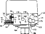
Fig. 3 is the end-view of pressure switch, for clarity sake has several places to do to analyse and observe;
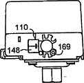
Fig. 4 is the front view of the used unloader of pressure switch, and expression is with the orientation of pressure fluid from Stirling engine emptying rear valve body;
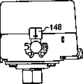
Fig. 5 similarly schemes with Fig. 4, but the orientation of the valve body of expression unloader when closing fully;
Fig. 6 similarly schemes with Figure 4 and 5, but the position of the valve member of expression unloader will open the time;
Fig. 7 is the front view of unloader outward appearance;
Fig. 8 is made up of to 8 (h) Fig. 8 (a), concentrates all places of each side in the both sides that on the arbitrary position that is illustrated in a plurality of positions of every side unloader are installed in pressure switch;
Fig. 9 is a front view, analyses and observe part and represents the cable fixture;
Figure 10 is roughly along the resulting partial sectional view of 10-10 line among Fig. 9;
Figure 11 is the phantom of an end of pressure switch;
Figure 12 is the end view of pressure switch, the manual parts of the contact of expression manual operation switch, and have several places to do to analyse and observe;
Figure 13 similarly schemes with Figure 12, but the position relation of the parts of expression switch when closed;
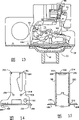
Figure 14 is the end view of the used carriage of processing switch;
Figure 15 is the view of the carriage seen from the right side of Figure 14.
Embodiment
Represented in these accompanying drawings is a typical embodiment of pressure switch.Should be appreciated that in the following description, although pressure switch usually relates to the situation under the air compressor environment, pressure switch of the present invention is applicable to fluid handling system, said here fluid can be liquid or gas.
Referring to Fig. 1, pressure switch comprises a base 20.Base 20 is generally U-shaped, has a notch board 22 (Fig. 3) and two upright side plates or support 24.As illustrated in fig. 1 and 2, each upright side plate 24 all comprises the hole 26 that is used to install a known conduit adapter sleeve.As a kind of selection, can use the cable fixture shown in Fig. 9 and 10.Cable fixed lever 30 comprises a centre bore 32 that is used to install a bolt 34, cable fixed lever 30 can be fixed on the upright end 36 of base 20 with bolt 34.Fixed lever 30 comprises the semicircle orifice of splitting to wall 36 38.As shown in figure 10, semicircle orifice 38 is zigzag, so that block cable and it is securely fixed on the base 20.
Referring to Fig. 1-3, this switch also comprises a lid 40 again, and it has formed and has not belonged to part of the present invention, and in other words it is known.40 relative with lid, a barrier film box 42 is installed on the notch board 22 of base 20, it has one or more holes 46 of linking to each other with monitored pressure source of being suitable for.With bolt 48 barrier film box 42 is fixed on the notch board 22 and with a barrier film 50 be clipped in notch board 22 below.A known hole (not shown) is arranged on notch board 22, and common bell top cover 52 is pressed on the opposite side facing to the barrier film 50 in hole 46, and can move in switch.
An inverted U-shaped carriage 53 that one compression helical spring 54 is housed is arranged in switch, and the back will be described in greater detail.One push pedal is installed on the end of thread 58 of bar 60, and bar 60 is upward through spring 54, and its end is the screw rod (not shown), just above carriage 53.The compression degree of rotating screw bolt adjustable springs.
The bell top cover 52 of bar 60 contacts.Therefore, 54 pairs of barrier films of spring 50 produce pressure, and its direction imposes on barrier film 50 from the fluid source that links to each other with hole 46 the direction of pressure is opposite.
It should be noted, in switch of the present invention, the bell top cover 52 of spring 54 direct bias voltages.This structure with prior art is different, and in prior art, spring is bias voltage one interlocking bar in fact, and hinge bar is pressed bell top cover 52 again.
Lid has in 40 one can be with the arc seat 62 of any insulating material making.As shown in Figure 1, on arc seat 62, fix a pair of electric contact that separates 64 and 66.Each electric contact 64 and 66 all stretches to a binding post bolt 60.Also have the movably contact 70 of an elongation in switch, it can shift to and remove contact 64,66.It can be connected two contacts thereby form the loop once moving.The mobile of contact 70 realizes that by first lever 72 first lever 72 is installed by hinging pin shaft 74, and bearing pin 54 hingedly is installed on the carriage 53, so as around trunnion axis around rotation.Under normal conditions, lever 72 is actually a part that has two arms as shown in the figure, is positioned at the both sides of carriage 53.Two movable contacts 70 are installed, and arc box installation two cover contacts 64 and 66, they are positioned at the two opposite sides of switch.
Contact with second thick stick 80 on hinging pin shaft 82 the right just as shown in Figure 1 at the pin 86 of the two opposite sides of bell top cover 52, should be applied to 46 places, hole pressure increase and make lever 80 make counter-clockwise swing.Suppose that lever 72 makes counter-clockwise swing from position shown in Figure 1 in advance, contact 70 and contact 64 and 66 are connected, second lever 80 continues to do counter-clockwise swing then made central authority 84 surmount the center, this can make first lever 72 sudden turn of events in the counterclockwise direction, opens or electric open position thereby movable contact 70 moved on to from closed or electric on-position.This open position as shown in Figure 1.
The same with first lever 72, second lever 80 is actually a part with identical arm as shown in Figure 1, in the two opposite sides of pressure switch one second lever 80 is arranged respectively.What should particularly point out is that the arm of each lever 72 all comprises an outwardly directed L shaped plate 88, and actuation surfaces 90 is arranged on it, and its purposes is obvious.
Referring now to Fig. 2,, pressure switch will have a differential pressure mechanism.Especially for example in the operation process of air compressor, be higher than when making closing of circuit begin the pressure of compressed-air actuated pressure reaching, must be that circuit disconnects.The front makes this point clear to the description of the air compressor course of work.Can utilize differential pressure mechanism to set differential pressure between two pressure, these two pressure are respectively corresponding to the cut-out pressure and the cut-in pressure of open and close circuit.
For this reason, arc box 62 comprises the cylindrical shell of an integral body, and a pin 90 that has major part 92 in cylindrical shell stretches out cross bar 94 (Fig. 1) contact that connects with 80 liang of relative parts transverselies of second lever.One compression helical spring 94 is arranged in the cylindrical shell, and it is pressing major part 92, will sell 90 and press to cross bar 94.Be threaded near the upper end of cylindrical shell, an expansion screw is screwed in wherein, thereby the bias voltage of spring is imposed on major part 92 and therefore imposes on pin 90, can regulate the bias voltage of spring.Because adjustment screw is carried out appropriate adjusting, the cut-out pressure of switch can be set.
According to the present invention, differential pressure mechanism can comprise second governor motion, and it is arranged on an arc seat 62 of the opposite side of cylindrical shell, and a screwed hole 100 is arranged in it.Screwed hole 100 is on cross bar 102, and cross bar 102 links to each other on lever 72 and with mistake central authority 84.One stop surface 104 100 stretches out from the hole.Stop surface 104 is in the end of the adjustment screw 104 that is screwed into hole 100.Stop surface 104 is on the stroke of cross bar 102 of first lever 72, and sets a stop, and restriction movable contact 70 leaves make position, promptly shifts to open position.Utilize the connection of this stop scalable switch.The working range and the monitoring range that never change switch set out with regard to the viewpoint of scalable differential pressure by regulating cut-in pressure, and this is needed.Therefore, be assumed to 689.5 thousand Newton/meter 2 (promptly 100 pounds/time 2) if preestablish cut-out pressure, as long as utilize adjustment screw 106 to regulate, even the scalable differential pressure, this pressure will remain unchanged.
Referring now to Fig. 3,, further feature of the present invention is described.As shown in the drawing, each sidewall 24 of base 20 is all installed a unloader 110.In fact under normal conditions, a unloader 110 only is installed.What Fig. 3 will represent is for the flexibility of production is provided, unloader 110 can be installed in each side of pressure switch.
To do concise and to the point the description to the details of each unloader, but for the purpose at hand, what should be specifically noted that is that each unloader all comprises an interface 112, it with system in to carry out pressure release the zone link to each other.Usually, this zone is the discharge chambe of Stirling engine such as compressor.
Unloader comprises a control valve rod 114, and it partly stretches in the switch by hole 116 (see figure 2)s on each sidewall 24.Suppose that unloader 110 is closed, bar 114 is pushed unloader unloader 110 is opened.
According to the present invention, utilize both arms crank throw 118 bar 114 can be pushed unloader 110.Both arms crank throw 118 comprises a center hinging pin shaft 120 and first and second lever arms 122 and 124 that stretch out from bearing pin 120.As shown in Figure 3, arm 122 be in can with valve rod 114 position contacting, this moment arm 114 on the actuation surfaces 90 of the L shaped plate 88 of first lever 72 (Fig. 1).
Referring to Fig. 1, will be understood that again when switch opens, first lever 72 is swung along clockwise direction, and actuation surfaces 90 is moved up.This makes the both arms crank throw 118 on the left side swing along clockwise direction around its hinging pin shaft 120, and valve rod 114 is pushed unloader 110, and valve 110 is opened.If unloader 110 is installed in the right of pressure switch as shown in Figure 3, actuation surfaces 90 moves up the both arms crank throw 118 on the right is swung in the counterclockwise direction, also valve rod 114 is pushed unloader 110, and valve 110 is opened.
In a preferred embodiment, the axle journal of hinging pin shaft 120 is (Figure 11) that the lip-deep recess of opening downwards 125 down by arc seat 62 forms.Shown in Fig. 3 and 11, the surface 126 of the contraction on hinging pin shaft 120 two opposite sides enters recessed 125 for hinging pin shaft 120 provides spigot surface, and the inlet of recess 125 is more slightly smaller than bearing pin 120, so that bearing pin 120 is maintained in the recess 125.
Fig. 4,5 and 6 illustrate in greater detail the structure of each unloader.Each unloader 110 all comprises a valve body that is made of an outer valve 130 and an inner valve body 132.Inner valve body 132 comprises that there is the passage 134 of an opening 136 its end, and valve rod 114 can stretch out from opening 136.Passage 134 comprises a shoulder 138.Shoulder 138 is valve seats of valve 140.Valve 140 comprises a central passage 142, and valve rod 114 stretches out from central passage 142, and shown in Figure 4 and 5, valve rod 114 has a lifting head 144, and it can close valve internal channel 142 and valve seat is pressed on the valve 140.
Just leave a bit of space between the end of the inner chamber 146 of the top of inner valve body 132 and outer valve 130, thereby the interface channel 148 that flows on the outer valve 130 to fluid provides passage, specifically, interface channel 148 is on a side of valve body 130.As can being clear that from Fig. 4-6, interface channel 148 is vertical with straight channel 134 usually, and be suitable for by any suitable device with to be linked to each other by the pressure source of emptying, for example link to each other with the discharge chambe of above-mentioned compressor.
Unloader also comprises a side outlet 150.Side outlet 150 is that the opening by the aligning on inner valve body 132 and the outer valve 130 limits, and with passage 134 fluid communication.
Last part of unloader is the spring 152 that is contained in the straight channel 134, and valve 140 leaves seat 138 under the bias voltage of spring 152, promptly shift to position shown in Figure 4.
Fig. 4 represents to be called the position of the parts under the entry condition.At this moment, do not provide pressure fluid to interface channel 148.Valve 140 can be opened, and lifting head 144 can be closed simultaneously.
When starting Stirling engine, its discharge chambe links to each other with interface channel 148, and pressure fluid enters unloader and flows to the left side of valve 140.The bias voltage of pressure fluid antagonistic spring 152 is pressed to position shown in Figure 5 with valve 140.In this position, valve 140 is pressed on the valve seat 138, and lifting head is pressed on the valve 140.Therefore, pressure fluid can not pass through unloader 110 emptying this moment.
When reaching cut-out pressure, the caused contact of clockwise swing of first lever 72 shown in Figure 1 is opened and can be made actuation surfaces 90 that both arms crank throw 118 is swung to position shown in Figure 6.This can make lifting head 144 leave valve 140, makes interface channel 148 and outlet 150 fluid communication.Owing to act on the fluid pressure difference of 140 liang of opposite ends of valve, valve 140 certainly will make the pressure at two ends equate.Therefore, spring 152 can make valve 140 get back to position shown in Figure 4.This has just realized the emptying that produced by valve 140, for example, so that reduce the startup load of Stirling engine, then reaches cut-in pressure.
As required, available plastic production inner valve body 132.Its outer wall can have round bar 154, and the sealing of the many places with excellent sealing effect is provided between outer valve 130 and inner valve body 132, and this structure of while is very economical again.
A key character of unloader 110 is that it comprises a plane 156.The guide end 158 of inner valve body 132 156 stretches out from the plane, normally leads and locate for unloader at the hole 116 of selected sidewall 24 (Fig. 2) interior.
As from Fig. 7 saw, a pair of leg 160 stretches out from outer valve 130 in the two relative orientation of demarcating.Each leg 160 all comprises a recess 162.Referring to Fig. 2, can see around opening 166, having three installing holes 164,166 and 168 at least again.A threaded fastener 169 enters any selected installing hole 164,166,168 by a selected recess 162, so that unloader 110 is fixed on the desired side of pressure switch as shown in Figure 3.Recess 162 that utilization separates by angle and the installing hole 164,166 that separates by angle and 168 and this erecting devices on two side 24 can be installed in unloader each side of pressure switch by the arbitrary position in a plurality of positions shown in Fig. 8 A to 8H.Note, can make progress on demand with the 156 parallel interface channels of opening 148, plane, downwards, towards the right side or towards a left side.Therefore, because interface channel 148 can be towards compressor, but i.e. position most convenient or link to each other with the discharge chambe of compressor most effectively all whatsoever, the structure of this pressure switch is desirable, is suitable for the different producer that the system zero parts have different relative positions and uses.
As noted earlier, another feature of the present invention is a manual actuator to be installed at the either side of switch.For this reason, as from Fig. 2 and 9 see that each sidewall 24 of switch all has an opening 170.Opening 170 comprises the central annulus part of being made up of two circular arcs 172 and 174, and circular arc 172 and 174 common length are slightly larger than 180 °.As meeting is seen, with they axle journals as manual actuator.
One first enlarged 176 enlarges along a direction from middle body, and as meeting was seen, first enlarged 176 had the profile of the cam face of manual actuator, but its contrast cam face is slightly larger.
One second enlarged 178 is arranged on the opposite of first enlarged 176.In a preferred embodiment, the arc length of enlarged 178 is 90 °, and its both sides 180 and 182 are stop surfaces.
Operable manual actuator such as Figure 11 are shown in 12 and 13.This manual actuator is included among Figure 11 the handle 184 of representing with solid line and dotting in Figure 12 and 13.One first axle journal 186 is bigger, stretches out from handle.First axle journal 186 comprises a radially-protruding ridge 188 and three or four radially-protruding teeth 190, and its amount of extending radially out is slightly larger than the diameter by the middle body of circular arc 172 and 174 openings that limited 170.
Again inwards, each manual actuator comprises one second axle journal 194, and it is located in the hole 196 of getting on the corresponding supporting leg 198 or 200 of carriage 53.
Can see with this,, just can install to manual actuator on the switch as long as cam 192 and enlarged 176 centerings are also pushed in the switch vertically.Cam 192 1 enters in the corresponding sidewall 24, just can the rotation manual actuator, make radially-protruding ridge 188 and enlarged 178 centerings.Manually retainer continues forward, and axle journal 194 is entered in the hole 196 on the carriage 53.Tooth 180 meeting strains are passed hole 170, are positioned at the lateral faces on handle 184 opposites.Herein, ridge 188 is positioned at a position of second enlarged 178, be pressed on any in stop surfaces 180 or 182, thereby can be with the limit rotation of each manual actuator to a certain degree.Certainly, first axle journal 186 can rotate in the circular arc 172 and 174 of opening 170.
At this moment, cam 192 is supporting second lever 80 from below.Therefore, if make handle 84 put position shown in Figure 2, cam 192 can make arm 80 along counter-clockwise swing, can make lever 72 along swing clockwise like this, opens the contact.On the other hand, when handle 84 was put position shown in Figure 13, second lever 80 was along putting position shown in Figure 13 clockwise.If being put usually, second lever 80 can not arrive, but apply the critical positions that bias voltage should arrive it for along clockwise direction second lever 80 if adopt biasing spring, second lever 80 relevant with first lever 72 can surmount the center, and make a lever 72 sudden turns of events to position shown in Figure 13, in this position, movable contact and fixing contacting.
Referring to Figure 11, it is worthy of note, with bolt 204 arc seat 62 is installed on the notch board 202 of carriage 53.It is worthy of note that equally the supporting leg 198 of carriage 53 and 200 end have outside leg 206 and 208 respectively, with threaded fastener leg 206 and 208 are fixed on the notch board 22 of base 20.For the sake of clarity threaded fastener does not illustrate.
It is worthy of note that equally each supporting leg 198 and 200 all has the location extension 208 in the hole 210 of the notch board 22 that stretches into base 20.Adopt this structure accurately supporting leg 198 and 200 to be spaced from each other.
Referring now to Figure 14 and 15,, carriage 53 is described in more detail.Can be clear that from Fig. 5 notch board 202 links to each other with 200 with supporting leg 198 by corresponding sweep 212,214.Similarly, two supporting legs 206 link to each other with corresponding supporting leg 198,200 by sweep 216.
Adopt general processing method crooked metal sheet just can realize this bending.On metallic plate, impact journal hole 196 before crooked and be used to install the hinging pin shaft 74 of first and second levers 72 and 80 and 82 hole 218 and 220.
Easy to understand, the hinging pin shaft installing hole 218 and 220 on the supporting leg 198,200 is centering more accurately, otherwise, can't assemble lever 72,80.Will be understood that equally, when bending operation, be difficult to realize accurate centering.Therefore, according to the present invention, in the punching technology process and before bending, at the final flat not sweep that forms supporting leg 198 and 200, the sweep 212 and 214 that is right after each supporting leg 198 and 200 forms a pair of protuberance 230.Similarly, at flat not sweep, be right after sweep 216 and form protuberance 232 in two opposite ends of each supporting leg 198 and 200.
Therefore, when installing to carriage 53 on the base 20, leg 206 is pressed on the base 20, but the final position of supporting leg 198 and 200 is depended on pressing with leg 208 of 232 pairs of notch boards 22 of protuberance and is entered in the location hole on the notch board 22.In this respect, as seeing from Figure 14 and 15, protuberance 232 is more lower slightly than the lower surface of leg 206.
Be stamped out journal hole 218 and 220 because protuberance 232 resembles, quite accurately determine their relative position,, can keep accurate relative position at any time owing to do not have bending operation in the middle of during punching press two protuberances 232.Therefore, press the protuberance 232 of the notch board of base 20 by setting,, make hinging journal hole 118 and 220 enough centering accurately mutually separately in the hole of notch board 22, be enough to finish assembly work by location leg 208 is set.
For other parts are accurately located, be to be noted that the structure of arc seat 62 should make its both sides at notch board 202 lean against on the protuberance 230.Arc seat 62 is fixed on the notch board 202 reliably but needn't be pressed on the notch board 202.Because protuberance 230 forms in the punching operation process, and be on unbending supporting leg 198 and 200, therefore can obtain same precision.In addition, equal protuberance 230 on the supporting leg 200 and 232 s' distance and, can improve the positional precision between parts by the distance that makes protuberance 230 on one of supporting leg 198 and 232 by making the journal hole on each supporting leg leave the same distance of corresponding protuberance.Therefore be contained in the fixed contact 64,66 on the arc seat 62 with first lever 72 that is contained on the carriage 53 on movable contact between more accurately locate and just can realize.
Referring to Figure 13, be to be noted that the notch board 22 of base 20 defines a more flat mounting plane again.Under normal conditions, in the system that pressure switch will be installed, require plano-concave plate 22 or parallel with the vibration-direction of for example compressor piston, or perpendicular.
According to the present invention, contact 64,66 and 70 is arranged to when make position at Figure 13, the folded angle of the mounting plane that they and notch board 22 are limited greater than 0 ° less than 90 °.Therefore, the contact can be in the principal oscillation plane of machine.So, the vibration of contact and too early wearing and tearing and/or burn with the possibility of arcing and reduce to minimum.
In a highly preferred embodiment, this angle greater than 100 ° less than 80 °, in illustrated embodiment, be 13 ° with angle perpendicular to the line on the plane of notch board 22.45 ° is best angle.The restriction in space usually requires to adopt less angle.In a preferred embodiment, consider to adopt 13 °.
Be appreciated that from the above mentioned pressure switch of the present invention done tangible improvement in many aspects.The device uniqueness of unloader is installed, therefore unloader can be installed in the either side of pressure switch, be easy to adapt to the different parts orientation of the different producers' fluid process system, or can unloader be installed on the pressure switch by a plurality of angle positions for identical purpose, or the two has it concurrently, just can satisfy all needs substantially with a kind of product in some sense, the manufacturing cost of pressure switch is reduced.
It is improvement to pressure switch that manual actuator is provided.This manual actuator can be installed on the arbitrary installation site in a plurality of installation sites on the pressure switch, also be easy to be fit to the different producers' special requirement.
The contact forms an angle during switch closure, makes the contact not in the principal oscillation plane, and this contact mounting structure has improved the life-span and the functional reliability of switch.Adopt crooked switch carriage to reduce manufacturing cost, simultaneously, adopt unique projection to guarantee the centering of appropriate section at the not sweep of switch, solved assembly problem, therefore, make the pressure switch reliable operation, cost is low.
Claims (4)
1. a pressure switch comprises a base, and one is fixed on the base and is suitable for bearing the barrier film of pressure fluid source;
Be installed in and between the open and close position, make the electric contact that relatively moves close mutually and that leave on the base; With
Mechanically be installed in the pressure that response acts on the barrier film between said barrier film and the said contact and realize the said leverage that relatively moves, one unloader is installed on said base, this valve is suitable for linking to each other with said pressure fluid source, when said contact is shown in an open position, this valve events, the pressure fluid of the said pressure fluid source of emptying and respond the device that said leverage is handled said unloader;
It is characterized in that said base has at least two devices that are used to install said unloader that separate, said operating device is installed near arbitrary said erecting device selectively.
2. according to the described pressure switch of claim 1, it is characterized in that, said unloader comprises that one has and is suitable for the interface channel that links to each other with said pressure fluid source and one and is suitable for the control valve that moved by operating means, said control valve is contained on the switch by a plane that is pressed against on the said base, the direction of said access opening roughly with said plane parallel, each said erecting device comprises that all the unloader that will have a said plane is installed in device on the said base by the unspecified angle position in a plurality of different angle position of the said interface channel relevant with said base.
3. according to the described pressure switch of claim 1, it is characterized in that said erecting device is included in a hole on the said base, can see through this hole and handle said unloader that a plurality of installing holes are arranged in said hole on every side.
4. according to the described pressure switch of claim 1, it is characterized in that, said operating device comprises a both arms crank throw, its arm can contact with said leverage, another arm can contact with said unloader, in the middle of said two arms, there are a hinging pin shaft, said base to comprise two bearing pin installing holes, contiguous each the said erecting device of each installing hole.
Priority Applications (1)
| Application Number | Priority Date | Filing Date | Title |
|---|---|---|---|
| CN96105592A CN1113373C (en) | 1996-02-16 | 1996-02-16 | Pressure switch |
Applications Claiming Priority (1)
| Application Number | Priority Date | Filing Date | Title |
|---|---|---|---|
| CN96105592A CN1113373C (en) | 1996-02-16 | 1996-02-16 | Pressure switch |
Publications (2)
| Publication Number | Publication Date |
|---|---|
| CN1187680A CN1187680A (en) | 1998-07-15 |
| CN1113373C true CN1113373C (en) | 2003-07-02 |
Family
ID=5118905
Family Applications (1)
| Application Number | Title | Priority Date | Filing Date |
|---|---|---|---|
| CN96105592A Expired - Fee Related CN1113373C (en) | 1996-02-16 | 1996-02-16 | Pressure switch |
Country Status (1)
| Country | Link |
|---|---|
| CN (1) | CN1113373C (en) |
Families Citing this family (2)
| Publication number | Priority date | Publication date | Assignee | Title |
|---|---|---|---|---|
| CN104323707B (en) * | 2014-11-10 | 2016-09-14 | 佛山市高明欧一电子制造有限公司 | The pressure breaker safe device of electric pressure cooking saucepan Non auto-reset |
| CN112146227B (en) * | 2020-08-31 | 2022-04-12 | 珠海格力电器股份有限公司 | Pressure detection switch, air conditioner control method and device, air conditioner and storage medium |
Citations (4)
| Publication number | Priority date | Publication date | Assignee | Title |
|---|---|---|---|---|
| US3235683A (en) * | 1961-04-12 | 1966-02-15 | Beeman Lyle | Air compressor control mechanism |
| US3875358A (en) * | 1974-02-19 | 1975-04-01 | Furnas Electric Co | Diaphragm snap pressure switch |
| US4868356A (en) * | 1988-09-22 | 1989-09-19 | Furnas Electric Company | Easily serviced fluid pressure operated switch |
| CN2139305Y (en) * | 1992-06-15 | 1993-07-28 | 罗强 | Pressure switch |
-
1996
- 1996-02-16 CN CN96105592A patent/CN1113373C/en not_active Expired - Fee Related
Patent Citations (4)
| Publication number | Priority date | Publication date | Assignee | Title |
|---|---|---|---|---|
| US3235683A (en) * | 1961-04-12 | 1966-02-15 | Beeman Lyle | Air compressor control mechanism |
| US3875358A (en) * | 1974-02-19 | 1975-04-01 | Furnas Electric Co | Diaphragm snap pressure switch |
| US4868356A (en) * | 1988-09-22 | 1989-09-19 | Furnas Electric Company | Easily serviced fluid pressure operated switch |
| CN2139305Y (en) * | 1992-06-15 | 1993-07-28 | 罗强 | Pressure switch |
Also Published As
| Publication number | Publication date |
|---|---|
| CN1187680A (en) | 1998-07-15 |
Similar Documents
| Publication | Publication Date | Title |
|---|---|---|
| CN1270117C (en) | Direct acting electric valve | |
| US10458402B2 (en) | Micro water pump capable of controlling flow precisely | |
| CN1227688C (en) | Vacuum circuit breaker | |
| CN1113373C (en) | Pressure switch | |
| CN106235910A (en) | The safety switching apparatus of food blending machine | |
| KR20170120395A (en) | A flow control valve actuators | |
| CN1989884A (en) | An electric pressure cooker | |
| CN1280859C (en) | switchgear | |
| CN1161809C (en) | Multi-position automatic switching actuator for load switch | |
| KR102927738B1 (en) | Liquid material discharging device and liquid material applying device | |
| KR20090121426A (en) | Flow control valve for linear flow control | |
| CN111852583A (en) | Changeable quick type intermittent type barring gear | |
| CN211046662U (en) | Electromechanical integrated locking device | |
| CN1696509A (en) | Rotating machinery and water supply | |
| CN109373055A (en) | A kind of multifunctional combination type pipe clamp of pipeline | |
| CN2662036Y (en) | Structure improvement for water outlet apparatus of hydrovalve | |
| CN205996633U (en) | Swing piston port cheats processing unit (plant) | |
| CN1357154A (en) | Fuse switch | |
| CN108798208A (en) | A kind of combined type lifting railing | |
| CN2672394Y (en) | Tilting plate type electric valve | |
| CN220706581U (en) | Pressure automatic controller for Chinese patent medicine extracting tank | |
| CN209309242U (en) | Feed screw nut and installing handle locking device | |
| CN116837941B (en) | A concealed faucet capable of quickly locating a panel installation position | |
| CN1279316C (en) | Gas cooker | |
| CN206516564U (en) | A kind of compression-type temperature controller forced shutdown structure |
Legal Events
| Date | Code | Title | Description |
|---|---|---|---|
| C06 | Publication | ||
| PB01 | Publication | ||
| C10 | Entry into substantive examination | ||
| SE01 | Entry into force of request for substantive examination | ||
| C14 | Grant of patent or utility model | ||
| GR01 | Patent grant | ||
| C17 | Cessation of patent right | ||
| CF01 | Termination of patent right due to non-payment of annual fee |
Granted publication date: 20030702 |