CN111331200A - Novel vertical numerical control sawing machine blank equipment - Google Patents
Novel vertical numerical control sawing machine blank equipment Download PDFInfo
- Publication number
- CN111331200A CN111331200A CN202010310077.4A CN202010310077A CN111331200A CN 111331200 A CN111331200 A CN 111331200A CN 202010310077 A CN202010310077 A CN 202010310077A CN 111331200 A CN111331200 A CN 111331200A
- Authority
- CN
- China
- Prior art keywords
- bottom plate
- plate
- numerical control
- sawing machine
- equipment body
- Prior art date
- Legal status (The legal status is an assumption and is not a legal conclusion. Google has not performed a legal analysis and makes no representation as to the accuracy of the status listed.)
- Withdrawn
Links
Images


Classifications
-
- B—PERFORMING OPERATIONS; TRANSPORTING
- B23—MACHINE TOOLS; METAL-WORKING NOT OTHERWISE PROVIDED FOR
- B23D—PLANING; SLOTTING; SHEARING; BROACHING; SAWING; FILING; SCRAPING; LIKE OPERATIONS FOR WORKING METAL BY REMOVING MATERIAL, NOT OTHERWISE PROVIDED FOR
- B23D79/00—Methods, machines, or devices not covered elsewhere, for working metal by removal of material
-
- B—PERFORMING OPERATIONS; TRANSPORTING
- B23—MACHINE TOOLS; METAL-WORKING NOT OTHERWISE PROVIDED FOR
- B23Q—DETAILS, COMPONENTS, OR ACCESSORIES FOR MACHINE TOOLS, e.g. ARRANGEMENTS FOR COPYING OR CONTROLLING; MACHINE TOOLS IN GENERAL CHARACTERISED BY THE CONSTRUCTION OF PARTICULAR DETAILS OR COMPONENTS; COMBINATIONS OR ASSOCIATIONS OF METAL-WORKING MACHINES, NOT DIRECTED TO A PARTICULAR RESULT
- B23Q3/00—Devices holding, supporting, or positioning work or tools, of a kind normally removable from the machine
- B23Q3/02—Devices holding, supporting, or positioning work or tools, of a kind normally removable from the machine for mounting on a work-table, tool-slide, or analogous part
- B23Q3/06—Work-clamping means
- B23Q3/062—Work-clamping means adapted for holding workpieces having a special form or being made from a special material
Abstract
The invention discloses novel vertical numerical control sawing machine cutting equipment which comprises a cutting equipment body, wherein a bottom plate is arranged at the top of the cutting equipment body, a connecting block is fixedly connected to the top of the bottom plate, an extrusion plate positioned at the top of the connecting block is arranged at the top of the bottom plate, the extrusion plate is sleeved on the surface of the output end of the cutting equipment body, and one side of the connecting block, far away from the bottom plate, penetrates through the extrusion plate and extends into the extrusion plate. According to the invention, the driving wheel is rotated through the handle, the position of the higher side of the driving wheel is exchanged with that of the other side of the driving wheel, the right side of the extrusion plate is pushed to ascend, the extrusion plate rotates by taking the connecting block as an axis and is contacted with the top of the plate, and then a user cuts the plate through the cutting equipment body, so that the problems that the existing numerical control sawing machine is complicated in raw material fixing mode, the fixing range is small, the plate is easy to vibrate when being cut and broken, and the edge of the plate is cracked are solved.
Description
Technical Field
The invention relates to the technical field of numerical control sawing machines, in particular to novel vertical numerical control sawing machine material cutting equipment.
Background
The numerical control sawing machine is an automatic processing device developed on the basis of a common sawing machine, the processing technology of the numerical control sawing machine and the processing technology of the numerical control sawing machine are basically the same, and the structures of the numerical control sawing machine and the numerical control sawing machine are also somewhat similar. The numerical control sawing machine is a numerical control machine with strong processing function, and a processing center, a flexible processing unit and the like which are rapidly developed are generated on the basis of the numerical control sawing machine.
The numerical control sawing machine usually cuts a product plate in advance, but the existing numerical control sawing machine is complicated in a raw material fixing mode and small in fixing range, and the plate is easy to vibrate when being cut and broken, so that the edge of the plate is prone to cracking.
Disclosure of Invention
Technical problem to be solved
Aiming at the defects of the prior art, the invention provides novel vertical numerical control sawing machine cutting equipment which has the advantages of improving the fixing stability and the like, and solves the problems that the conventional numerical control sawing machine is complicated in raw material fixing mode, small in fixing range and prone to generate vibration when a plate is cut and broken, so that the edge of the plate is cracked.
(II) technical scheme
In order to achieve the purpose, the invention provides the following technical scheme: the utility model provides a novel vertical numerical control sawing machine blank equipment, includes blank equipment body, the top of blank equipment body is provided with the bottom plate, the top fixedly connected with connecting block of bottom plate, the top of bottom plate is provided with the stripper plate that is located the connecting block top, the stripper plate cover is established on the surface of blank equipment body output, one side that the bottom plate was kept away from to the connecting block runs through the stripper plate and extends to the inside of stripper plate, the stripper plate passes through round pin axle swing joint with the connecting block, there is the drive wheel that is located the stripper plate bottom at the top of bottom plate through bearing swing joint, the top of drive wheel and the bottom contact of stripper plate, the positive fixedly connected with handle of drive wheel.
Preferably, the top fixedly connected with guide arm of blank equipment body, the bottom plate that the one end of blank equipment was run through is kept away from to the guide arm and extends to the top of bottom plate, guide arm and bottom plate sliding connection, the quantity of guide arm is four and is located the four corners of bottom plate bottom.
Preferably, the surface of the guide rod is in threaded connection with a threaded sleeve positioned at the bottom of the bottom plate, and the top of the threaded sleeve is in contact with the bottom of the bottom plate.
Preferably, the both sides of stripper plate and the back of bottom plate equal fixedly connected with pull rod, the surperficial cover of pull rod is equipped with the extension spring.
Preferably, the top of the blanking device body is fixedly connected with a positioning frame sleeved on the surface of the guide rod, the inner surface of the positioning frame is in contact with the surface of the guide rod, and the positioning frame is made by bending a steel plate.
Preferably, the bottom fixedly connected with cover of stripper plate is established at the cushion on blank equipment body output surface, the bottom of cushion has seted up anti-skidding line, the material of cushion is silica gel.
(III) advantageous effects
Compared with the prior art, the invention provides novel vertical numerical control sawing machine cutting equipment, which has the following beneficial effects:
1. this novel vertical numerical control sawing machine blank equipment, through handle rotary drive wheel, the higher one side of drive wheel exchanges and promotes the right side of stripper plate with the opposite side position and rises, the stripper plate uses the connecting block to rotate as the axle center and contact with the top of panel, then the user cuts panel through the blank equipment body, it is comparatively loaded down with trivial details to the fixed mode of raw materials to have solved current numerical control sawing machine, and the fixed range is less moreover, the panel produces vibrations easily when cutting fracture, the problem that the edge that leads to the panel appears the phenomenon of bursting apart.
2. This novel vertical numerical control sawing machine blank equipment, through setting up the guide arm, can play the effect of direction to the bottom plate, avoid the bottom plate to remove the in-process slope, and can the person of facilitating the use dismantle the bottom plate, through setting up the swivel nut, can play the effect of support to the bottom plate, the person of facilitating the use highly adjusts the height of bottom plate according to panel, through setting up pull rod and extension spring, can play towed effect to the stripper plate, can stimulate the stripper plate to reset when drive wheel breaks away from the contact with the stripper plate, through setting up the locating frame, can improve the area of contact of guide arm and blank equipment body, avoid the junction of guide arm and blank equipment body to appear the rupture because of the bearing is too high, through setting up the cushion, can improve the fixed effect of stripper plate, increase the frictional force between stripper plate and the panel.
Drawings
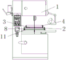
FIG. 1 is a schematic structural view of the present invention;
FIG. 2 is a schematic front view of a partial structure of the present invention;
FIG. 3 is a right-view schematic diagram of a partial structure of the present invention;
FIG. 4 is a schematic top view of a partial structure of the present invention.
In the figure: 1 cutting equipment body, 2 bottom plates, 3 connecting blocks, 4 extrusion plates, 5 transmission wheels, 6 handles, 7 guide rods, 8 threaded sleeves, 9 pull rods, 10 tension springs, 11 positioning frames and 12 rubber mats.
Detailed Description
The technical solutions in the embodiments of the present invention will be clearly and completely described below with reference to the drawings in the embodiments of the present invention, and it is obvious that the described embodiments are only a part of the embodiments of the present invention, and not all of the embodiments. All other embodiments, which can be derived by a person skilled in the art from the embodiments given herein without making any creative effort, shall fall within the protection scope of the present invention.
Referring to fig. 1-4, a novel vertical numerical control sawing machine cutting device comprises a cutting device body 1, a bottom plate 2 is arranged at the top of the cutting device body 1, guide rods 7 are fixedly connected to the top of the cutting device body 1, one end of each guide rod 7, which is far away from the cutting device, penetrates through the bottom plate 2 and extends to the top of the bottom plate 2, the guide rods 7 are slidably connected with the bottom plate 2, the number of the guide rods 7 is four, and are positioned at four corners of the bottom plate 2, the guide rods 7 can guide the bottom plate 2 to prevent the bottom plate 2 from inclining in the moving process, and can facilitate a user to disassemble the bottom plate 2, threaded sleeves 8 positioned at the bottom of the bottom plate 2 are connected to the surfaces of the guide rods 7, the tops of the threaded sleeves 8 are in contact with the bottom of the bottom plate 2, and can support the bottom plate 2 by arranging the threaded sleeves 8, so that the user can adjust the height of the bottom plate, the top of the cutting equipment body 1 is fixedly connected with a positioning frame 11 sleeved on the surface of a guide rod 7, the inner surface of the positioning frame 11 is contacted with the surface of the guide rod 7, the positioning frame 11 is made by bending a steel plate, the contact area between the guide rod 7 and the cutting equipment body 1 can be improved by arranging the positioning frame 11, the fracture of the joint of the guide rod 7 and the cutting equipment body 1 due to overhigh bearing is avoided, the top of the bottom plate 2 is fixedly connected with a connecting block 3, the top of the bottom plate 2 is provided with an extrusion plate 4 positioned at the top of the connecting block 3, both sides of the extrusion plate 4 and the back of the bottom plate 2 are both fixedly connected with pull rods 9, the surface of each pull rod 9 is sleeved with a tension spring 10, the tension effect on the extrusion plate 4 can be achieved by arranging the pull rods 9 and the tension springs 10, the extrusion plate 4 can be pulled to reset when the driving wheel 5 is separated from the extrusion plate 4, the bottom, anti-skidding line has been seted up to the bottom of cushion 12, the material of cushion 12 is silica gel, through setting up cushion 12, can improve stripper plate 4's fixed effect, increase the frictional force between stripper plate 4 and the panel, the surface at 1 output of blank equipment body is established to stripper plate 4 cover, stripper plate 4 is run through and extends to stripper plate 4 in one side that bottom plate 2 was kept away from to connecting block 3, stripper plate 4 and connecting block 3 are through round pin axle swing joint, there is drive wheel 5 that is located stripper plate 4 bottom at the top of bottom plate 2 through bearing swing joint, the top of drive wheel 5 and the bottom contact of stripper plate 4, the positive fixedly connected with handle 6 of drive wheel 5.
When using, place panel at the top of blank equipment body 1 and be located the bottom of stripper plate 4, then rotate drive wheel 5 through handle 6, the higher one side of drive wheel 5 exchanges and promotes the right side of stripper plate 4 with the other side position and rise, stripper plate 4 uses connecting block 3 as the axle center rotation and with the top contact of panel, then the user cuts panel through blank equipment body 1, when needs adjust the height of stripper plate 4 according to panel thickness, can reach the effect of supporting the height of bottom plate 2 through changing the position of swivel nut 8.
To sum up, this novel vertical numerical control sawing machine blank equipment, through 6 swivelling drive wheel 5 of handle, the higher one side of drive wheel 5 exchanges and promotes the right side of stripper plate 4 with the other side position and rises, stripper plate 4 uses connecting block 3 to rotate and contact with the top of panel as the axle center, then the user cuts panel through blank equipment body 1, it is comparatively loaded down with trivial details to the fixed mode of raw materials to have solved current numerical control sawing machine, and fixed range is less, the panel produces vibrations easily when cutting fracture, the problem that the edge that leads to the panel appears bursting apart the phenomenon.
It is noted that, herein, relational terms such as first and second, and the like may be used solely to distinguish one entity or action from another entity or action without necessarily requiring or implying any actual such relationship or order between such entities or actions. Also, the terms "comprises," "comprising," or any other variation thereof, are intended to cover a non-exclusive inclusion, such that a process, method, article, or apparatus that comprises a list of elements does not include only those elements but may include other elements not expressly listed or inherent to such process, method, article, or apparatus.
Although embodiments of the present invention have been shown and described, it will be appreciated by those skilled in the art that changes, modifications, substitutions and alterations can be made in these embodiments without departing from the principles and spirit of the invention, the scope of which is defined in the appended claims and their equivalents.
Claims (6)
1. The utility model provides a novel vertical numerical control sawing machine blank equipment, includes blank equipment body (1), its characterized in that: the top of blank equipment body (1) is provided with bottom plate (2), the top fixedly connected with connecting block (3) of bottom plate (2), the top of bottom plate (2) is provided with stripper plate (4) that are located connecting block (3) top, stripper plate (4) cover is established on the surface of blank equipment body (1) output, one side that bottom plate (2) were kept away from in connecting block (3) runs through stripper plate (4) and extends to the inside of stripper plate (4), stripper plate (4) and connecting block (3) are through round pin axle swing joint, there is drive wheel (5) that are located stripper plate (4) bottom at the top of bottom plate (2) through bearing swing joint, the top of drive wheel (5) and the bottom contact of stripper plate (4), the front fixedly connected with handle (6) of drive wheel (5).
2. The novel vertical numerical control sawing machine blanking device according to claim 1, characterized in that: the top fixedly connected with guide arm (7) of blank equipment body (1), bottom plate (2) that the one end of blank equipment run through is kept away from in guide arm (7) and extend to the top of bottom plate (2), guide arm (7) and bottom plate (2) sliding connection, the quantity of guide arm (7) is four and is located the four corners of bottom plate (2) bottom.
3. The novel vertical numerical control sawing machine blanking device according to claim 2, characterized in that: the surface of the guide rod (7) is in threaded connection with a threaded sleeve (8) positioned at the bottom of the bottom plate (2), and the top of the threaded sleeve (8) is in contact with the bottom of the bottom plate (2).
4. The novel vertical numerical control sawing machine blanking device according to claim 1, characterized in that: the equal fixedly connected with pull rod (9) in both sides of stripper plate (4) and the back of bottom plate (2), the surperficial cover of pull rod (9) is equipped with extension spring (10).
5. The novel vertical numerical control sawing machine blanking device according to claim 1, characterized in that: the top fixedly connected with cover of blank equipment body (1) is established at locating frame (11) on guide arm (7) surface, the internal surface of locating frame (11) and the surface contact of guide arm (7), locating frame (11) are bent for the steel sheet and are made.
6. The novel vertical numerical control sawing machine blanking device according to claim 1, characterized in that: the bottom fixedly connected with cover of stripper plate (4) is established at rubber mat (12) on blank equipment body (1) output terminal surface, anti-skidding line has been seted up to the bottom of rubber mat (12), the material of rubber mat (12) is silica gel.
Priority Applications (1)
| Application Number | Priority Date | Filing Date | Title |
|---|---|---|---|
| CN202010310077.4A CN111331200A (en) | 2020-04-20 | 2020-04-20 | Novel vertical numerical control sawing machine blank equipment |
Applications Claiming Priority (1)
| Application Number | Priority Date | Filing Date | Title |
|---|---|---|---|
| CN202010310077.4A CN111331200A (en) | 2020-04-20 | 2020-04-20 | Novel vertical numerical control sawing machine blank equipment |
Publications (1)
| Publication Number | Publication Date |
|---|---|
| CN111331200A true CN111331200A (en) | 2020-06-26 |
Family
ID=71177235
Family Applications (1)
| Application Number | Title | Priority Date | Filing Date |
|---|---|---|---|
| CN202010310077.4A Withdrawn CN111331200A (en) | 2020-04-20 | 2020-04-20 | Novel vertical numerical control sawing machine blank equipment |
Country Status (1)
| Country | Link |
|---|---|
| CN (1) | CN111331200A (en) |
Citations (7)
| Publication number | Priority date | Publication date | Assignee | Title |
|---|---|---|---|---|
| US9545704B2 (en) * | 2014-06-06 | 2017-01-17 | Glenn Guillot | Through cutting mill steady rest |
| CN106363437A (en) * | 2016-11-30 | 2017-02-01 | 雅安泛华工装模具有限责任公司 | CNC (Computer Numerical Control) machining fixture |
| CN207205867U (en) * | 2017-06-03 | 2018-04-10 | 昆山瑞来博精密金属有限公司 | Clamping jig for CNC processing |
| CN207771352U (en) * | 2017-10-31 | 2018-08-28 | 镇江市长虹散热器有限公司 | Radiator clamp for machining |
| CN208147415U (en) * | 2018-05-04 | 2018-11-27 | 南京农业大学 | A kind of edge cam fast fixture |
| CN208289467U (en) * | 2018-06-11 | 2018-12-28 | 西安邮电大学 | Columnar workpiece self-locking compressing fixture |
| CN209850375U (en) * | 2018-12-14 | 2019-12-27 | 四川省正迪鑫科技有限公司 | Fixture for fixing |
-
2020
- 2020-04-20 CN CN202010310077.4A patent/CN111331200A/en not_active Withdrawn
Patent Citations (7)
| Publication number | Priority date | Publication date | Assignee | Title |
|---|---|---|---|---|
| US9545704B2 (en) * | 2014-06-06 | 2017-01-17 | Glenn Guillot | Through cutting mill steady rest |
| CN106363437A (en) * | 2016-11-30 | 2017-02-01 | 雅安泛华工装模具有限责任公司 | CNC (Computer Numerical Control) machining fixture |
| CN207205867U (en) * | 2017-06-03 | 2018-04-10 | 昆山瑞来博精密金属有限公司 | Clamping jig for CNC processing |
| CN207771352U (en) * | 2017-10-31 | 2018-08-28 | 镇江市长虹散热器有限公司 | Radiator clamp for machining |
| CN208147415U (en) * | 2018-05-04 | 2018-11-27 | 南京农业大学 | A kind of edge cam fast fixture |
| CN208289467U (en) * | 2018-06-11 | 2018-12-28 | 西安邮电大学 | Columnar workpiece self-locking compressing fixture |
| CN209850375U (en) * | 2018-12-14 | 2019-12-27 | 四川省正迪鑫科技有限公司 | Fixture for fixing |
Similar Documents
| Publication | Publication Date | Title |
|---|---|---|
| CN110922041B (en) | Self-suction float glass cutting device | |
| CN211539681U (en) | Numerical control cutting fixing mechanism of handicraft | |
| CN108637371B (en) | A kind of Furniture panel cutting machine convenient for clamping | |
| CN112405187A (en) | Stainless steel punching plate manufacturing and processing machine | |
| CN209224294U (en) | A kind of indoor water that construction uses establishes scouring machine by cable | |
| CN111331200A (en) | Novel vertical numerical control sawing machine blank equipment | |
| CN111546435A (en) | Cutting machine for producing plate-type furniture | |
| CN112266160B (en) | Processing device for tempered glass convenient to cut | |
| CN113427341B (en) | Industrial brush edge burr polishing device capable of collecting scraps and use method thereof | |
| CN213950028U (en) | Printing material device of taking | |
| CN110432348B (en) | Tea rolling equipment | |
| CN211250905U (en) | Ceramic tile cutting device for interior decoration | |
| CN210525293U (en) | Carbon fiber cutting device is used in laboratory | |
| CN208977870U (en) | A kind of cutting machine | |
| CN208163714U (en) | A kind of efficient slicer of rubber | |
| CN112338686A (en) | Stainless steel hole punching plate machining method | |
| CN218947798U (en) | Cutting mechanism for composite material preparation | |
| CN216578021U (en) | Cutting device for automatic rubber forming | |
| CN208948505U (en) | A kind of waterproof material film cutter device | |
| CN218488667U (en) | Concrete shaking table | |
| CN213647655U (en) | Contact lens mould guillootine | |
| CN212238636U (en) | Multifunctional wire passing frame for production of fishing line drawing | |
| CN211645285U (en) | Leather product edge trimmer | |
| CN215847459U (en) | Metal product polishing center | |
| CN219504463U (en) | Polishing equipment for furniture production |
Legal Events
| Date | Code | Title | Description |
|---|---|---|---|
| PB01 | Publication | ||
| PB01 | Publication | ||
| SE01 | Entry into force of request for substantive examination | ||
| SE01 | Entry into force of request for substantive examination | ||
| WW01 | Invention patent application withdrawn after publication |
Application publication date: 20200626 |
|
| WW01 | Invention patent application withdrawn after publication |