CN111322233B - Sampling circuit and method for improving precision, compressor and air conditioning equipment - Google Patents
Sampling circuit and method for improving precision, compressor and air conditioning equipment Download PDFInfo
- Publication number
- CN111322233B CN111322233B CN202010128907.1A CN202010128907A CN111322233B CN 111322233 B CN111322233 B CN 111322233B CN 202010128907 A CN202010128907 A CN 202010128907A CN 111322233 B CN111322233 B CN 111322233B
- Authority
- CN
- China
- Prior art keywords
- sampling
- branch
- compressor
- module
- sampling branch
- Prior art date
- Legal status (The legal status is an assumption and is not a legal conclusion. Google has not performed a legal analysis and makes no representation as to the accuracy of the status listed.)
- Active
Links
Images


Classifications
-
- F—MECHANICAL ENGINEERING; LIGHTING; HEATING; WEAPONS; BLASTING
- F04—POSITIVE - DISPLACEMENT MACHINES FOR LIQUIDS; PUMPS FOR LIQUIDS OR ELASTIC FLUIDS
- F04B—POSITIVE-DISPLACEMENT MACHINES FOR LIQUIDS; PUMPS
- F04B49/00—Control, e.g. of pump delivery, or pump pressure of, or safety measures for, machines, pumps, or pumping installations, not otherwise provided for, or of interest apart from, groups F04B1/00 - F04B47/00
- F04B49/06—Control using electricity
- F04B49/065—Control using electricity and making use of computers
-
- H—ELECTRICITY
- H03—ELECTRONIC CIRCUITRY
- H03K—PULSE TECHNIQUE
- H03K19/00—Logic circuits, i.e. having at least two inputs acting on one output; Inverting circuits
- H03K19/0175—Coupling arrangements; Interface arrangements
Abstract
The invention discloses a sampling circuit and method for improving precision, a compressor and air conditioning equipment. Wherein, this sampling circuit includes: a sampling module connected between the compressor and a reference ground, comprising: the sampling module is controlled by the digital signal processor to change the conduction state; the first input end of the operation module is connected between the compressor and the sampling module, the second input end of the operation module is connected with a reference ground, and the operation module is used for performing operation processing on the voltage output by the sampling module to obtain a sampling voltage; and the digital signal processor is connected with the operation module and controls the conduction state according to the sampling voltage subjected to operation processing. According to the invention, the total resistance value of the sampling module can be adaptively changed, and more accurate current sampling is realized when the current of the compressor is lower, so that the compressor is more accurately controlled.
Description
Technical Field
The invention relates to the technical field of electronic power, in particular to a sampling circuit and method for improving precision, a compressor and air conditioning equipment.
Background
In the existing frequency conversion driving air conditioner technology, the current of a compressor is sampled through a single resistor. When the compressor current is small, the sampling voltage of the sampling resistor also becomes small. Due to the possible reasons of superposition interference and the like, when the current of the compressor is small under the condition of not changing the gain of the operational amplifier, the accuracy of the sampling value after the operational amplifier is lower than that in the normal condition, so that the control of the compressor in the condition is influenced.
Aiming at the problem that the sampling precision can become lower when the sampling voltage is reduced along with the current of the compressor in the prior art, an effective solution is not provided at present.
Disclosure of Invention
The embodiment of the invention provides a sampling circuit and method for improving precision, a compressor and air conditioning equipment, and aims to solve the problem that sampling precision is low when sampling voltage is reduced along with current of the compressor in the prior art.
In order to solve the above technical problem, the present invention provides a sampling circuit for improving accuracy, wherein the sampling comprises: the device comprises a sampling module, an operation module and a digital signal processor;
the sampling module is connected between the compressor and a reference ground and comprises: the first sampling branch and the second sampling branch are arranged between the compressor and a reference ground in parallel, and the first sampling branch and/or the second sampling branch change the conduction state under the control of the digital signal processor;
the first input end of the operation module is connected between the compressor and the sampling module, the second input end of the operation module is connected with a reference ground, and the output end of the operation module is connected with the digital signal processor and is used for outputting the sampling voltage output by the sampling module to the digital signal processor after operation processing;
and the digital signal processor is respectively connected with the operation module and the sampling module and is used for controlling the conduction state according to the sampling voltage subjected to operation processing.
Further, the on state refers to: and the first sampling branch circuit and the second sampling branch circuit are selected to be conducted, or the first sampling branch circuit and the second sampling branch circuit are all conducted.
Further, a switch is arranged on the first sampling branch and/or the second sampling branch, and the switch is switched on or off under the control of the digital signal processor.
Further, the first sampling branch comprises at least one first resistor, and the second sampling branch comprises at least one second resistor.
Further, the first resistor and the second resistor are constant resistors.
The invention also provides a compressor, which comprises the sampling circuit for providing the precision.
The invention also provides air conditioning equipment comprising the compressor.
The invention also provides a sampling method for improving the precision, which is applied to the sampling circuit for improving the precision and comprises the following steps:
acquiring a sampling voltage value;
and controlling the conduction state of the first sampling branch and/or the second sampling branch according to the sampling voltage value.
Further, controlling the conducting state of the first sampling branch and/or the second sampling branch according to the sampling voltage value includes:
if the sampling voltage value is smaller than a first preset value, controlling one of the first sampling branch circuit and the second sampling branch circuit to be conducted;
and if the sampling voltage value is greater than or equal to the first preset value, controlling the first sampling branch and the second sampling branch to be completely conducted.
Further, after controlling the first sampling branch and the second sampling branch to be alternatively conducted, the method further includes:
judging whether the current sampling voltage value is greater than or equal to a second preset value; wherein the second preset value is greater than the first preset value;
if yes, controlling the first sampling branch and the second sampling branch to be conducted completely;
if not, continuously keeping the first sampling branch and the second sampling branch to be alternatively conducted.
Further, controlling the first sampling branch and the second sampling branch to be alternatively conducted includes: controlling the switch of the first sampling branch or the switch of any branch in the second sampling branch to be turned off;
controlling the first sampling branch and the second sampling branch to be conducted completely, including: and controlling the switch of the first sampling branch circuit and the switch of the second sampling branch circuit to be conducted.
The present invention also provides a computer-readable storage medium having stored thereon a computer program which, when executed by a processor, implements the above-described accuracy-improving sampling method.
By applying the technical scheme of the invention, the total resistance value of the sampling module is changed by changing the conduction state of the first sampling branch and the second sampling branch, when the sampling voltage is reduced along with the current of the compressor, the total resistance value of the sampling module can be adaptively changed, more accurate current sampling is realized when the current of the compressor is lower, and thus, the compressor is more accurately controlled.
Drawings
FIG. 1 is a block diagram of a sampling circuit according to an embodiment of the present invention;
FIG. 2 is a block diagram of a sampling circuit according to another embodiment of the present invention;
FIG. 3 is a block diagram of a sampling circuit according to yet another embodiment of the present invention;
fig. 4 is a flow chart of a sampling method according to an embodiment of the present invention.
Detailed Description
In order to make the objects, technical solutions and advantages of the present invention clearer, the present invention will be described in further detail with reference to the accompanying drawings, and it is apparent that the described embodiments are only a part of the embodiments of the present invention, not all of the embodiments. All other embodiments, which can be derived by a person skilled in the art from the embodiments given herein without making any creative effort, shall fall within the protection scope of the present invention.
The terminology used in the embodiments of the invention is for the purpose of describing particular embodiments only and is not intended to be limiting of the invention. As used in the examples of the present invention and the appended claims, the singular forms "a", "an", and "the" are intended to include the plural forms as well, unless the context clearly indicates otherwise, and "a plurality" typically includes at least two.
It should be understood that the term "and/or" as used herein is merely one type of association that describes an associated object, meaning that three relationships may exist, e.g., a and/or B may mean: a exists alone, A and B exist simultaneously, and B exists alone. In addition, the character "/" herein generally indicates that the former and latter related objects are in an "or" relationship.
It should be understood that although the terms first, second, third, etc. may be used to describe the resistors in the embodiments of the present invention, the resistors should not be limited to these terms. These terms are only used to distinguish between different resistances. For example, a first resistance may also be referred to as a second resistance, and similarly, a second resistance may also be referred to as a first resistance, without departing from the scope of embodiments of the present invention.
The words "if", as used herein, may be interpreted as "at … …" or "at … …" or "in response to a determination" or "in response to a detection", depending on the context. Similarly, the phrases "if determined" or "if detected (a stated condition or event)" may be interpreted as "when determined" or "in response to a determination" or "when detected (a stated condition or event)" or "in response to a detection (a stated condition or event)", depending on the context.
It is also noted that the terms "comprises," "comprising," or any other variation thereof, are intended to cover a non-exclusive inclusion, such that an article or apparatus that comprises a list of elements does not include only those elements but may include other elements not expressly listed or inherent to such article or apparatus. Without further limitation, an element defined by the phrase "comprising an … …" does not exclude the presence of other like elements in the article or device in which the element is included.
Alternative embodiments of the present invention are described in detail below with reference to the accompanying drawings.
Example 1
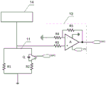
The present embodiment provides a sampling circuit with improved accuracy, fig. 1 is a structural diagram of a sampling circuit according to an embodiment of the present invention, and as shown in fig. 1, the sampling circuit includes a sampling module 11, an operation module 12 and a digital signal processor 13; the sampling module 11, connected between the compressor 14 and the reference ground, comprises: a first sampling branch 111 and a second sampling branch 112 arranged in parallel between the compressor and a reference ground, wherein the first sampling branch 111 and/or the second sampling branch 112 change conduction state under the control of the digital signal processor 13; the first input end of the operation module 12 is connected between the compressor 14 and the sampling module 11, the second input end of the operation module is connected with a reference ground, and the output end of the operation module is connected with the digital signal processor 13, and the operation module is used for performing operation processing on the sampling voltage output by the sampling module 11 and outputting the sampling voltage to the digital signal processor 13; the digital signal processor 13 is connected to the operation module 12 and the sampling module 11, and configured to control a conduction state of the first sampling branch 111 and/or the second sampling branch 112 according to the sampling voltage subjected to the operation processing, so as to change a total resistance of the sampling module 11, where the conduction state refers to: and the first sampling branch circuit and the second sampling branch circuit are selected to be conducted, or the first sampling branch circuit and the second sampling branch circuit are all conducted.
The sampling circuit of this embodiment, through the on-state that changes first sampling branch road and second sampling branch road, changes sampling module 11's total resistance, when sampling voltage reduces along with compressor current, can change sampling module 11's total resistance adaptively, realizes carrying out more accurate current sampling when compressor current is lower to carry out more accurate control to the compressor.
Example 2
In this embodiment, another sampling circuit with improved accuracy is provided, and fig. 2 is a structural diagram of a sampling circuit according to another embodiment of the present invention, in order to control the on state of the first sampling branch 111 and/or the second sampling branch 112, as shown in fig. 2, a switch Q is disposed on the second sampling branch 112, and the switch Q is connected to a second interface DSP2 of the digital signal processor and is connected to be turned on or turned off under the control of the digital signal processor.
In order to realize that the total resistance of the sampling module 11 formed by the first sampling branch 111 and the second sampling branch 112 is variable, the first sampling branch 111 includes at least one first resistor R1, and the second sampling branch 112 includes at least one second resistor R2, in this embodiment, the number of the first resistors R1 and the number of the second resistors R2 are both 1, in other embodiments of the present invention, the first sampling branch 111 may include a plurality of first resistors R1 connected in series, or a plurality of first resistors R1 are combined in series and parallel to form a resistor network, wherein the conduction of each parallel branch may be controlled individually, similarly, the second sampling branch 112 may also include a plurality of second resistors R2 connected in series, or a plurality of second resistors R2 are combined in series and parallel to form a resistor network, wherein the conduction of each parallel branch may be controlled individually.
In a specific implementation, in order to facilitate the analysis and calculation of the total resistance of the sampling circuit, the first resistor R1 and the second resistor R2 are constant resistors, and their resistances are fixed.
Since the voltage output by the sampling module 11 is an analog signal and the input signal of the digital signal processor 13 needs to be a digital signal, the voltage output by the sampling module 11 needs to be operated and can be received and read by the digital signal processor 13, and therefore the operation module 12 includes: an operational amplifier A; a third resistor R3, wherein a first end of the third resistor R3 is connected between the sampling module 11 and the compressor 14, and a second end is connected to the positive input terminal of the operational amplifier a, for limiting the input voltage at the positive input terminal of the operational amplifier a, and preventing the input voltage at the positive input terminal of the operational amplifier a from being too high and exceeding the operating voltage of the operational amplifier a; and a fourth resistor R4, connected between the inverting input terminal of the operational amplifier and the reference ground, for limiting the input voltage at the inverting input terminal of the operational amplifier a so that the input voltage at the inverting input terminal is not zero, and the output terminal of the operational amplifier a is connected to the first interface DSP1 of the digital signal processor.
In the above operation module 12, in order to increase the system stability, and increase the input impedance and decrease the output impedance, it may further include: and the fifth resistor R5 is connected between the output end of the operational amplifier A and the inverting input end of the operational amplifier, and is used for feeding back part of the output signal of the operational amplifier A to the inverting input end thereof so as to achieve the purposes of increasing the system stability, increasing the input impedance and reducing the output impedance.
Since the operational amplifier needs to operate at a certain voltage, the operational amplifier a further includes: the third input end is connected with a reference ground, and the fourth input end is connected with a voltage source VCC for supplying a working power supply to the operational amplifier A.
Example 3
This embodiment provides another sampling circuit with improved accuracy, and fig. 3 is a structural diagram of a sampling circuit according to another embodiment of the present invention, as shown in fig. 3, the sampling circuit includes: the Digital Signal Processor (DSP) comprises a first sampling resistor R31, a second sampling resistor R32, an operational amplifier positive phase input end resistor R33, an operational amplifier negative phase input end resistor R34, a feedback resistor R35, a switch tube Q1, an operational amplifier U1-A and a digital signal processor, wherein the second sampling resistor R32 is selected according to the maximum current which can be borne by the switch tube Q1, the first sampling resistor R31 is selected according to the second sampling resistor R32 and the rated current of the compressor, when the current of the compressor is large, an I/O port corresponding to the DSP outputs high level, when the current of the compressor is reduced to 1/10 to 1/5 of the rated current of the compressor, the DSP judges that the sampling voltage value is changed into V1 correspondingly according to the received voltage, and sets V1 as a first threshold value.
When the sampling voltage value is smaller than the first threshold value V1, the current of the compressor is judged to be low at the moment, the switch tube Q1 is controlled to be turned off, only the first sampling resistor R32 is turned on, the sampling resistance value is correspondingly increased by 5-10 times, the DSP correspondingly changes the software value of the sampling voltage, the voltage of the operational amplifier positive phase input end is improved, and the sampling precision is further improved.
In order to prevent the operational amplifier from entering saturation, a second threshold V2 is set, and the second threshold V2 is slightly lower than the operational amplifier power supply voltage VCC, for example, if VCC is 3.3V, the second threshold V2 may be set to 3.0V, when the switching tube Q1 is controlled to be turned off, and after only the first sampling resistor R32 is turned on, the sampling voltage value is increased to a certain threshold V2, it is determined that the compressor current is separated from a low-current state, the I/O port corresponding to the DSP outputs a high level, the switching tube Q1 is turned on, and the sampling resistance value is reduced, so as to prevent the operational amplifier from entering saturation.
In this embodiment, when the compressor current is large, the switching tube Q1 is in a conducting state. The first sampling resistor R31 and the second sampling resistor R32 are in a parallel state, the sampling resistance value is R31// R32 ═ R31 ═ R32/(R31+ R32), when the compressor current is reduced to 1/10 to 1/5 of the rated current of the compressor, the switching tube Q1 is in an off state, the sampling resistance value is R1 at the time, namely R31// R32 ═ R1, and as R31 ≧ R31 ═ R32/(R31+ R32), when the compressor current is reduced to 1/10 to 1/5 of the rated current of the compressor, the sampling resistance value is large, and the voltage of the operational amplifier positive phase input terminal can be increased.
In this embodiment, in order to reduce the current flowing through the switching tube Q1 when the first sampling resistor R31 and the second sampling resistor R32 are connected in parallel, when the first sampling resistor R31 and the second sampling resistor R32 are connected in parallel, the current I flowing through the switching tube Q1 may be set to be the compressor current × R31/(R31+ R32) by setting the resistance of R32 to be large and the resistance of R31 to be small.
In this embodiment, when the branch current of the second sampling resistor R32 is small, for example, below 6V, the switching tube Q1 may be a MOSFET; when the current of the branch where the second sampling resistor R32 is located is large, the switching tube may be an IGBT.
Example 4
The present embodiment provides a compressor including the sampling circuit with improved accuracy in the above embodiments.
Example 5
The embodiment provides an air conditioning equipment, including the compressor in embodiment 4 for promote the sampling precision of compressor, realize carrying out more accurate current sampling when the compressor current is lower, thereby carry out more accurate control to the compressor.
Example 6
The embodiment provides a sampling method with improved accuracy, which is applied to the sampling circuit with improved accuracy, and fig. 4 is a flowchart of the sampling method according to the embodiment of the invention, as shown in fig. 4, the method includes:
s101, acquiring a sampling voltage value;
and S102, controlling the conduction state of the first sampling branch and/or the second sampling branch according to the sampling voltage value.
In order to implement the control of one of the first sampling branch and the second sampling branch to be conducted or all to be conducted according to the sampling voltage value, step S102 specifically includes: if the sampling voltage value is smaller than the first preset value, controlling the first sampling branch circuit and the second sampling branch circuit to be selected and conducted so as to improve the resistance value of the sampling module and further improve the sampling voltage; if the sampling voltage value is larger than or equal to the first preset value, the first sampling branch circuit and the second sampling branch circuit are controlled to be completely conducted so as to reduce the resistance value of the sampling module and further reduce the sampling voltage.
If the sampling voltage is greater than or equal to the power voltage of the operation module, the operation module is saturated, and in order to avoid the phenomenon, after the first sampling branch and the second sampling branch are controlled to be alternatively conducted, the method further comprises the following steps: judging whether the current sampling voltage value is greater than or equal to a second preset value; the second preset value is larger than the first preset value, and the second threshold value is set according to the power supply voltage of the operation module; if the sampling voltage is close to the power supply voltage of the operation module, the first sampling branch and the second sampling branch are required to be controlled to be completely conducted, and the sampling voltage is reduced; if not, the first sampling branch and the second sampling branch are continuously kept to be alternatively conducted.
When the concrete implementation, control first sampling branch road and the alternative of second sampling branch road and switch on, include: controlling the switch of the first sampling branch or the switch of any branch in the second sampling branch to be switched off; controlling the first sampling branch and the second sampling branch to be conducted completely, including: and controlling the switch of the first sampling branch circuit and the switch of the second sampling branch circuit to be conducted.
The sampling circuit of this embodiment, through the on-state that changes first sampling branch road and second sampling branch road, changes the total resistance of sampling module, when sampling voltage reduces along with compressor current, can change the total resistance of sampling module adaptively, realizes carrying out more accurate current sampling when compressor current is lower to carry out more accurate control to the compressor.
Example 7
The present embodiment provides a computer-readable storage medium on which a computer program is stored, which when executed by a processor implements the above-described sampling method of improved accuracy.
Through the above description of the embodiments, those skilled in the art will clearly understand that each embodiment can be implemented by software plus a necessary general hardware platform, and certainly can also be implemented by hardware. With this understanding in mind, the above-described technical solutions may be embodied in the form of a software product, which can be stored in a computer-readable storage medium, such as ROM/RAM, magnetic disk, optical disk, etc., and includes instructions for causing a computer device (which may be a personal computer, a server, or a network device, etc.) to execute the methods of the various embodiments or some parts of the embodiments.
Finally, it should be noted that: the above examples are only intended to illustrate the technical solution of the present invention, but not to limit it; although the present invention has been described in detail with reference to the foregoing embodiments, it will be understood by those of ordinary skill in the art that: the technical solutions described in the foregoing embodiments may still be modified, or some technical features may be equivalently replaced; and such modifications or substitutions do not depart from the spirit and scope of the corresponding technical solutions of the embodiments of the present invention.
Claims (9)
1. A sampling circuit is characterized by comprising a sampling module, an operation module and a digital signal processor;
the sampling module is connected between the compressor and a reference ground and comprises: the first sampling branch and the second sampling branch are arranged between the compressor and a reference ground in parallel, and the first sampling branch and/or the second sampling branch change the conduction state under the control of the digital signal processor; wherein, the conducting state is as follows: the first sampling branch and the second sampling branch are selected to be conducted, or the first sampling branch and the second sampling branch are all conducted;
the first input end of the operation module is connected between the compressor and the sampling module, the second input end of the operation module is connected with a reference ground, and the output end of the operation module is connected with the digital signal processor and is used for outputting the sampling voltage output by the sampling module to the digital signal processor after operation processing;
and the digital signal processor is respectively connected with the operation module and the sampling module and is used for controlling the conduction state according to the sampling voltage subjected to operation processing.
2. The sampling circuit according to claim 1, wherein a switch is provided on the first sampling branch and/or the second sampling branch, and the switch is turned on or off under the control of the digital signal processor.
3. The sampling circuit of claim 1, wherein the first sampling branch comprises at least one first resistor and the second sampling branch comprises at least one second resistor.
4. The sampling circuit of claim 3, wherein the first resistor and the second resistor are fixed resistors.
5. A compressor, characterized in that it comprises a sampling circuit according to any one of claims 1 to 4.
6. An air conditioning apparatus, characterized by comprising the compressor of claim 5.
7. A sampling method applied to the sampling circuit according to any one of claims 1 to 4, comprising:
acquiring a sampling voltage value;
controlling the conducting state of the first sampling branch and/or the second sampling branch according to the sampling voltage value, wherein the method comprises the following steps: if the sampling voltage value is smaller than a first preset value, controlling one of the first sampling branch circuit and the second sampling branch circuit to be conducted;
and if the sampling voltage value is greater than or equal to the first preset value, controlling the first sampling branch and the second sampling branch to be completely conducted.
8. The method of claim 7, wherein after controlling the first sampling branch and the second sampling branch to be alternatively turned on, the method further comprises:
judging whether the current sampling voltage value is greater than or equal to a second preset value; wherein the second preset value is greater than the first preset value;
if yes, controlling the first sampling branch and the second sampling branch to be conducted completely;
if not, continuously keeping the first sampling branch and the second sampling branch to be alternatively conducted.
9. A computer-readable storage medium, on which a computer program is stored, which, when being executed by a processor, carries out the sampling method according to claim 7 or 8.
Priority Applications (1)
| Application Number | Priority Date | Filing Date | Title |
|---|---|---|---|
| CN202010128907.1A CN111322233B (en) | 2020-02-28 | 2020-02-28 | Sampling circuit and method for improving precision, compressor and air conditioning equipment |
Applications Claiming Priority (1)
| Application Number | Priority Date | Filing Date | Title |
|---|---|---|---|
| CN202010128907.1A CN111322233B (en) | 2020-02-28 | 2020-02-28 | Sampling circuit and method for improving precision, compressor and air conditioning equipment |
Publications (2)
| Publication Number | Publication Date |
|---|---|
| CN111322233A CN111322233A (en) | 2020-06-23 |
| CN111322233B true CN111322233B (en) | 2021-03-12 |
Family
ID=71171300
Family Applications (1)
| Application Number | Title | Priority Date | Filing Date |
|---|---|---|---|
| CN202010128907.1A Active CN111322233B (en) | 2020-02-28 | 2020-02-28 | Sampling circuit and method for improving precision, compressor and air conditioning equipment |
Country Status (1)
| Country | Link |
|---|---|
| CN (1) | CN111322233B (en) |
Families Citing this family (2)
| Publication number | Priority date | Publication date | Assignee | Title |
|---|---|---|---|---|
| CN114594704B (en) * | 2020-12-07 | 2023-08-01 | 山东新松工业软件研究院股份有限公司 | Motor inner ring control method, motor inner ring control device and motor inner ring control controller |
| CN113937962A (en) * | 2021-11-15 | 2022-01-14 | 江苏科技大学 | Device and method for improving current sampling precision of permanent magnet synchronous motor at low speed |
Family Cites Families (8)
| Publication number | Priority date | Publication date | Assignee | Title |
|---|---|---|---|---|
| US6456139B1 (en) * | 2000-10-20 | 2002-09-24 | Sun Microsystems, Inc. | Auto-detection and auto-enable of compact PCI bus pull-ups |
| CN101924547B (en) * | 2009-06-12 | 2012-02-15 | 苏州源赋创盈微电子科技有限公司 | Current sampling device |
| CN203011991U (en) * | 2012-12-10 | 2013-06-19 | 珠海格力电器股份有限公司 | Current sampling circuit and motor |
| CN103698594A (en) * | 2013-12-31 | 2014-04-02 | 广东易事特电源股份有限公司 | Detection range-adjustable current detection circuit and method |
| CN104678153B (en) * | 2015-02-28 | 2018-05-29 | 杭州茂力半导体技术有限公司 | Current detection circuit and electric current detecting method and battery power detection circuit |
| CN205450098U (en) * | 2015-12-28 | 2016-08-10 | 广东芬尼克兹节能设备有限公司 | Current transformer module |
| CN205407644U (en) * | 2016-02-24 | 2016-07-27 | 核工业理化工程研究院 | Detection circuitry of intermediate frequency undercurrent |
| US9882482B1 (en) * | 2016-09-15 | 2018-01-30 | Monolithic Power Systems, Inc. | Current sense circuit with adaptive common mode voltage adjust and associated method thereof |
-
2020
- 2020-02-28 CN CN202010128907.1A patent/CN111322233B/en active Active
Also Published As
| Publication number | Publication date |
|---|---|
| CN111322233A (en) | 2020-06-23 |
Similar Documents
| Publication | Publication Date | Title |
|---|---|---|
| CN111322233B (en) | Sampling circuit and method for improving precision, compressor and air conditioning equipment | |
| US11467611B2 (en) | Current limiting electronic fuse circuit | |
| WO2013173771A1 (en) | Integrated start-up bias boost for dynamic error vector magnitude enhancement | |
| US10459468B1 (en) | Load current sense circuit | |
| US20120154044A1 (en) | Class-D Amplifier Circuit | |
| US20180262188A1 (en) | Over-voltage clamp circuit | |
| KR20180111628A (en) | Overcurrent protection circuit and voltage regulator | |
| CN113315089B (en) | High-power supply rejection ratio load switching circuit and control method thereof | |
| JP2007215300A (en) | Power supply | |
| US8582267B2 (en) | System and method to limit in-rush current | |
| CN110620498A (en) | Constant-power type rapid discharge circuit | |
| JP2008011585A (en) | Switching regulator | |
| CN107797602B (en) | Miller compensation circuit and corresponding regulator, system and method | |
| CN115529041A (en) | Sectional optional signal conditioning circuit and measuring device | |
| TW201234156A (en) | Method and circuit for adapter soft start current control in a low drop-out regulator | |
| CN210246297U (en) | Load control output circuit with output short-circuit protection | |
| CN111290465B (en) | Low-dropout voltage stabilizer | |
| CN109032234B (en) | Constant current source device for limiting voltage threshold | |
| CN110690683A (en) | Overcurrent protection circuit and overcurrent protection device of intelligent power module | |
| CN220473902U (en) | Linear voltage stabilizing circuit and micro-processing chip | |
| JP2002090406A (en) | Constant-current and constant-resistance electronic load device | |
| CN215580369U (en) | Current overshoot suppression circuit based on negative feedback principle | |
| CN219997167U (en) | Current sampling circuit and chip | |
| CN110504655B (en) | Load control output circuit with output short-circuit protection and control method thereof | |
| CN104880975B (en) | Low-voltage chip controls the interface circuit and low-voltage control circuit of high tension apparatus |
Legal Events
| Date | Code | Title | Description |
|---|---|---|---|
| PB01 | Publication | ||
| PB01 | Publication | ||
| SE01 | Entry into force of request for substantive examination | ||
| SE01 | Entry into force of request for substantive examination | ||
| GR01 | Patent grant | ||
| GR01 | Patent grant |