CN1113144C - Higne for connecting adjacent wall or door elements - Google Patents
Higne for connecting adjacent wall or door elements Download PDFInfo
- Publication number
- CN1113144C CN1113144C CN98800008A CN98800008A CN1113144C CN 1113144 C CN1113144 C CN 1113144C CN 98800008 A CN98800008 A CN 98800008A CN 98800008 A CN98800008 A CN 98800008A CN 1113144 C CN1113144 C CN 1113144C
- Authority
- CN
- China
- Prior art keywords
- connector
- support
- unit
- tumbler
- face
- Prior art date
- Legal status (The legal status is an assumption and is not a legal conclusion. Google has not performed a legal analysis and makes no representation as to the accuracy of the status listed.)
- Expired - Fee Related
Links
- 239000011521 glass Substances 0.000 claims description 6
- 238000013461 design Methods 0.000 claims description 4
- 238000013507 mapping Methods 0.000 claims description 2
- 230000015572 biosynthetic process Effects 0.000 claims 1
- 238000004519 manufacturing process Methods 0.000 description 3
- 238000003466 welding Methods 0.000 description 2
- 229910000838 Al alloy Inorganic materials 0.000 description 1
- 230000009471 action Effects 0.000 description 1
- 230000008901 benefit Effects 0.000 description 1
- 230000008859 change Effects 0.000 description 1
- 230000000295 complement effect Effects 0.000 description 1
- 230000001419 dependent effect Effects 0.000 description 1
- 230000006872 improvement Effects 0.000 description 1
- 239000004615 ingredient Substances 0.000 description 1
- 238000012423 maintenance Methods 0.000 description 1
- 239000000463 material Substances 0.000 description 1
- 238000000034 method Methods 0.000 description 1
- 210000003205 muscle Anatomy 0.000 description 1
- 230000008569 process Effects 0.000 description 1
- 238000012545 processing Methods 0.000 description 1
- 239000002023 wood Substances 0.000 description 1
Images


Classifications
-
- E—FIXED CONSTRUCTIONS
- E05—LOCKS; KEYS; WINDOW OR DOOR FITTINGS; SAFES
- E05D—HINGES OR SUSPENSION DEVICES FOR DOORS, WINDOWS OR WINGS
- E05D3/00—Hinges with pins
- E05D3/06—Hinges with pins with two or more pins
- E05D3/08—Hinges with pins with two or more pins for swing-doors, i.e. openable by pushing from either side
-
- E—FIXED CONSTRUCTIONS
- E05—LOCKS; KEYS; WINDOW OR DOOR FITTINGS; SAFES
- E05Y—INDEXING SCHEME ASSOCIATED WITH SUBCLASSES E05D AND E05F, RELATING TO CONSTRUCTION ELEMENTS, ELECTRIC CONTROL, POWER SUPPLY, POWER SIGNAL OR TRANSMISSION, USER INTERFACES, MOUNTING OR COUPLING, DETAILS, ACCESSORIES, AUXILIARY OPERATIONS NOT OTHERWISE PROVIDED FOR, APPLICATION THEREOF
- E05Y2900/00—Application of doors, windows, wings or fittings thereof
- E05Y2900/10—Application of doors, windows, wings or fittings thereof for buildings or parts thereof
- E05Y2900/13—Type of wing
- E05Y2900/132—Doors
Landscapes
- Engineering & Computer Science (AREA)
- Mechanical Engineering (AREA)
- Hinges (AREA)
- Securing Of Glass Panes Or The Like (AREA)
- Wing Frames And Configurations (AREA)
- Door And Window Frames Mounted To Openings (AREA)
- Extensible Doors And Revolving Doors (AREA)
- Conveying And Assembling Of Building Elements In Situ (AREA)
- Support Devices For Sliding Doors (AREA)
Abstract
The invention relates to a hinge for connecting door or wall elements which are pivoted in relation to each other up to a mutually parallel position. The hinge has guide rods positioned crosswise one on top of each other. They are mounted in or on connecting elements which are fastenable to the door or wall element. The invention is characterized in that the hinge has a holder reaching through an opening in one wall of the connecting element. The holder can be connected, to the wall or door element via its holder shaft, and separates the guide rods and forms or accommodates the axis arms of the guide rods.
Description
The present invention relates to a kind of be used to the connect adjacent wall unit that is foldable to the position that is parallel to each other each other or the hinge of gate cell, it has the connector that is located at wall unit or the distolateral place of gate cell, wherein, always two opposed connectors connect by means of the tumbler that is contained in to cross arrangement in the connector groove up and down, and the end face that connector faces one another is designed to protruding and leaves a little space.
Hinge by the known a kind of the above-mentioned type of european patent application 0 528 032 A1.
In this known hinge, connector by means of screw detachably or by means of the welding non-disconnectable formula be fixed in the groove of suspender member.Therefore connector and suspender member form two independent members.Though in this known devices, adjacent door leaf can turn round 380 ° up to the position that is parallel to each other by means of the lever that is arranged above and below and intersects, can between adjacent door leaf, not form tangible space, but owing to being connected between connector and suspender member adopt wood screw to form a weak spot, so only allow to transmit less power during with respect to another gate cell revolution at a gate cell.Under the situation of connector with respect to the suspender member welding no longer is a kind of removable connection, and this is disadvantageous for repairing or changing each unit especially.Especially when heavy wall or gate cell for example require to transmit bigger power under the situation of glass door, can not adopt the disclosed scheme of above-mentioned application.
Therefore the objective of the invention is the hinge of the described type of preface is done following improvement, transmit bigger power so that adopt under the situation of can be more convenient than hinge and being easy to assemble in maintenance.
The purpose that is proposed reaches by Patent right requirement 1 described instruction.
The member that is called connector here constitutes the connector that connects adjacent door or wall unit and suspender member simultaneously, and suspender member is used for being connected with real wall or gate cell.Therefore, press the independent member of the instruction of european patent application 0 528 032 A1, be designed to one by the present invention.
Do like this connector might be designed comparatively robust, so, can enough insert in wall or the gate cell (or in corresponding door track) and can be fixed on the there deeply by its support handle by the Patent right requirement 1 described firm support that passes connector.Because the support termination of support broadening abuts on the bottom land of connector, so the spacing of these two opposed connectors is fixing exactly.Therefore connector is fixed in wall or the gate cell by support that is the force closure of support handle and shape sealedly and is fixed on wall or the gate cell.
By described other features of the present invention as can be known of the characteristic of dependent claims.
By claim 2, the external surface that the support termination faces one another is designed to the external surface that faces one another with connector that is the end face that faces one another is consistent.Take this measure to guarantee also only to form a little space, injured danger is arranged so in the linkage zone that constitutes by hinge, also got rid of at the bracket end Head Section.
By claim 3, the tumbler of each cross arrangement is contained between the plane of the plane of the inherent support of groove termination and connector.Therefore these two tumblers are separated by the support termination, that is to say no longer need by european patent application open file 0 528032 A1 that quote previously propose at the company's muscle between the tumbler up and down.
For on the one hand in good being connected of acquisition between support handle and wall or gate cell or its door track, and the support handle obtains supporting accurately in connector on the other hand, the Cross-section Design of support handle is square or rectangle, and simultaneously, the cross section of breach in connector and support handle is complementary.The support handle has some corresponding holes, and screwed hole preferably is used for being connected with wall or gate cell or its door track.
By another key character of the present invention, connector be divided into again two of mutual mirror image mapping half and constitute protruding end face respectively half, these two half available screws couple together.The most handy aluminium alloys manufacturing of known this type of connector is so the advantage that here obtains is cost saving that is is convenient to process and especially save material and reduces the manufacturing of weight ground.
Because connector may constitute suspender member simultaneously, so they can have the mounting groove of a wall or gate cell, it is preferably used in installs and fastening glass panels.
Press the instruction of european patent application 0 528 032 A1, the end face that adjacent connector faces one another is designed to be equivalent to the curve shape of half ellipse, and the tumbler that is in upper-lower position and intersection is configured to mutually orthogonal.Yet the manufacturing of this semiellipse curve is compared with the curve shape of circle, needs the complicated processing of additional expense expenditure.
But in design of the present invention, when adjacent wall or gate cell gyration, can obtain the little space that a width remains unchanged, for this reason, flush when arranging tumbler at adjacent wall or gate cell and be arranged to X-shaped and intersect and form an about angle of 52 °, the angular bisector of angle constitutes the center line of wall or gate cell; And the end face that connector faces one another is designed to extend semicirclely.
The hinge of the described type of a kind of preface that adopted the invention success, it is particularly useful for connecting two heavier adjacent walls or gate cell, so even wall or gate cell are arranged in the stand that is parallel to each other when repeating to act from the use location that flushes to wall or gate cell, can in the connector zone, produce wearing and tearing yet and can not block.
Describe the present invention in detail by means of a kind of possible embodiment that schematically illustrates below.Wherein:
The view of two upper and lower connections in adjacent door unit of Fig. 1;
Fig. 2 schematically illustrates at gate cell in the figure that compared to Figure 1 amplifies and flushes
The time linkage vertical view;
Fig. 3 presses the vertical view of Fig. 2 each other behind the knuckle at gate cell;
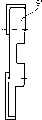
The various views of half of Fig. 4 to 8 connector, compared to Figure 1 slightly enlargedly
Expression;
Two half shown in Fig. 4 to 8 of Fig. 9 are combined into looking of a connector
Figure;
Figure 10,11 supports; And
Figure 12,13 tumblers.
Represent adjacent unit with 1 and 2 in Fig. 1 to 3, they are made of glass plate 6 by Fig. 1. Unit 1,2 rolls or guiding on slide rail 4 slidably by hanging 3 in the known manner.Hinge 7 both had been contained in the door track 5 and also had been contained in down in the door track 5 '.Can find out also that by Fig. 1 to 3 it is distolateral 8 that unit 1,2 faces one another, is positioned at one in front and one in back by keeping a little space X.Be also shown in by Fig. 1, be provided with connector 9 in door track 5,5 ' zone, tumbler 11,11 ' is contained in the connector.Support 15 is contained between the tumbler 11,11 ', and two tumblers 11,11 ' are separated in its support termination 17, and its support handle 16 is by being connected with door track 5 or 5 ' with the holes in the 23 support handles of representing 16.As can be seen, between the adjacent face 12 of connector 9 and between 17 external surfaces 20 of support termination, leave the little space X as between the adjacent cells 1,2.
Drawn linkage has clearly demonstrated this two tumblers that are arranged above and below across 11,11 ' in Fig. 2 and 3, and wherein, last tumbler 11 is bearing on the pivot pin 19, and following tumbler 11 ' is bearing on the pivot pin 19 '.The mode of action of relevant this type of linkage can be referring to disclosed content among european patent application 0 528 032 A1.
Press Fig. 2,1,2 flush when arranging in the unit, and these two tumblers 11,11 ' form about 52 ° of angle ground and are the X-shaped intersection, and the angular bisector of this angle has constituted the center line M of unit 1,2.The end face 12 that connector faces one another is designed to extend semicirclely.Because the distance Y between the center of circle of above-mentioned semicircle, even still remain unchanged during with respect to another unit 1 knuckle, so the space of representing with X does not change yet at a unit 2.
Half of usefulness 9 ' expression of in Fig. 4 to 8, having represented connector 9.Half of connector 9 ' has a groove 10, and the bottom land 13 of groove has constituted the border of the wall that half usefulness of 9 ' 14 of connector 9 represents.Wall 14 has a foursquare breach 18, is designed to foursquare support handle 16 equally and passes this breach.When connector 9 assembled, the support termination 17 of support 15 broadenings abutted on the bottom land 13 with its end face 26 force closures and shape sealedly.Meanwhile, support termination 17 separates these two tumblers 11,11 ', and in this case, tumbler 11,11 ' is bearing on the plane 22 of connector 9 on the one hand, is bearing on the other hand on the plane 21 of support termination 17.The external surface 20 of support termination 17 is designed to as one man extend with the end face 19 of connector 9.Rotatablely moving of tumbler 11 at figure paper plane internal upper part undertaken by pivot pin 19, rotatablely moving of the tumbler 11 ' of bottom undertaken by pivot pin 19 ' in the figure paper plane, pivot pin 19,19 ' preferably constitutes the ingredient of support in this case, that is to say with support and can not be connected with relatively rotating.
Press Fig. 9, these two half 9 ', 9 ", the screw by means of the hole 24 of passing among the figure symbolic expression is combined into a connector 9; mounting groove that usefulness 25 is represented as can be seen, it is used to install and fixes a glass plate that constitutes this element 1 in this embodiment.
Symbol table
3 hang
4 slide rails
5 door tracks
5 ' door track
6 glass plates
7 hinges
8 walls or gate cell distolateral
9 connectors
Half of 9 ' connector
9 " half of connector
10 grooves
Tumbler on 11
11 ' time tumbler
The end face of 12 connectors
13 bottom lands
The wall of 14 connectors
15 supports
16 support handles
17 support terminations
18 breach
Pivot pin on 19
19 ' lower shaft pin
The external surface of 20 support terminations
The plane of 21 support terminations
The plane of 22 connectors
Screwed hole in the 23 support handles
24 holes
25 mounting grooves
The bearing surface of 26 support terminations
The X space
The M center line
The Y distance
Claims (9)
1. be used to connect the adjacent wall unit that is foldable to the position that is parallel to each other each other or the hinge of gate cell, it has the connector that is located at wall unit or the distolateral place of gate cell, wherein, always two opposed connectors connect by means of the tumbler that is contained in to cross arrangement in the connector groove up and down, and, the end face that connector faces one another is designed to protruding and leaves a little space, it is characterized by: the wall (14) of the formation bottom land (13) of connector (9) has a breach (18) that is passed by the support handle (16) of support (15), support handle (16) can be fixed on unit (1,2) in or unit (1,2) last or unit (1,2) appendage, and, support (15) have one with respect to support handle (16) broadening support termination (17), it abuts in that bottom land (13) is gone up and constitutes or tumbler (11 is installed, 11 ') pivot pin (19,19 ').
2. according to the described hinge of claim 1, it is characterized by: external surface (20) design that support termination (17) face one another is consistent with the end face (12) that connector (9) faces one another.
3. according to claim 1 or 2 described hinges, its feature is being: the tumbler of each cross arrangement (11,11 ') is contained between the inner plane (21) and the plane (22) of connector (9) in support termination (17) of groove (10).
4. according to claim 1 or 2 described hinges, it is characterized by: support handle (16) Cross-section Design is square or rectangle.
5. according to claim 1 or 2 described hinges, it is characterized by: support handle (16) has some holes, and preferably screwed hole (23) is used for being connected with unit (1,2).
6. according to claim 1 or 2 described hinges, it is characterized by: connector (9) be divided into again two of mutual mirror image mapping half (9 ', 9 ") and constitute half protruding end face (12) respectively.
7. according to the described hinge of claim 6, it is characterized by: the two halves of connector (9) (9 ', 9 ") can couple together by means of screw.
8. according to claim 1 or 2 described hinges, it is characterized by: connector (9) has the mounting groove (25) of a unit (1,2), the preferably mounting groove of glass plate (6).
9. according to the described hinge of claim 2, it is characterized by: when adjacent cells (1,2) flushed arrangement, tumbler (11,11 ') formed about 52 ° of angle ground and is the X-shaped intersection, and the angular bisector of this angle constitutes the center line (M) of unit (1,2); And the end face (12) that connector (9) faces one another is designed to extend semicirclely.
Applications Claiming Priority (2)
| Application Number | Priority Date | Filing Date | Title |
|---|---|---|---|
| DE19704490A DE19704490C1 (en) | 1997-02-07 | 1997-02-07 | Hinge for connecting adjacent wall or door components |
| DE19704490.5 | 1997-02-07 |
Publications (2)
| Publication Number | Publication Date |
|---|---|
| CN1244229A CN1244229A (en) | 2000-02-09 |
| CN1113144C true CN1113144C (en) | 2003-07-02 |
Family
ID=7819484
Family Applications (1)
| Application Number | Title | Priority Date | Filing Date |
|---|---|---|---|
| CN98800008A Expired - Fee Related CN1113144C (en) | 1997-02-07 | 1998-02-05 | Higne for connecting adjacent wall or door elements |
Country Status (13)
| Country | Link |
|---|---|
| US (1) | US6073673A (en) |
| EP (1) | EP0892882B1 (en) |
| CN (1) | CN1113144C (en) |
| AT (1) | ATE246763T1 (en) |
| AU (1) | AU734165B2 (en) |
| CZ (1) | CZ295672B6 (en) |
| DE (2) | DE19704490C1 (en) |
| DK (1) | DK0892882T3 (en) |
| ES (1) | ES2203935T3 (en) |
| HU (1) | HU223626B1 (en) |
| PL (1) | PL192552B1 (en) |
| SK (1) | SK285096B6 (en) |
| WO (1) | WO1998035120A1 (en) |
Families Citing this family (7)
| Publication number | Priority date | Publication date | Assignee | Title |
|---|---|---|---|---|
| JP3136287B2 (en) * | 1998-08-07 | 2001-02-19 | 株式会社八木熊 | Folding moving fence |
| US6574837B2 (en) * | 2001-04-03 | 2003-06-10 | Versare Solutions, Inc. | 360° lockable hinge |
| US9033145B2 (en) * | 2003-11-26 | 2015-05-19 | Butler Leasing Corporation | Postal mailer for stress-sensitive articles |
| US7669389B2 (en) * | 2003-11-26 | 2010-03-02 | Butler Leasing Corporation | Two-way postal mailing assembly |
| US10655383B2 (en) * | 2016-03-22 | 2020-05-19 | Olson Kundig, Inc. | System and method for implementing an improved bi-fold shutter |
| US11053720B1 (en) | 2020-03-19 | 2021-07-06 | Timothy Marick | Hinge and methods of mounting and using a hinge |
| CN114183025A (en) * | 2021-12-22 | 2022-03-15 | 中山市福瑞卫浴设备有限公司 | Hinge structure |
Family Cites Families (8)
| Publication number | Priority date | Publication date | Assignee | Title |
|---|---|---|---|---|
| US328342A (en) * | 1885-10-13 | robinson | ||
| US2135280A (en) * | 1936-08-27 | 1938-11-01 | Erickson John | Hinge |
| US2178271A (en) * | 1937-08-05 | 1939-10-31 | Soss Joseph | Concealed hinge |
| US3881221A (en) * | 1974-01-14 | 1975-05-06 | Sos Consolidated | Invisible hinge |
| GB2224308A (en) * | 1988-09-29 | 1990-05-02 | Systemworks Limited | Connector |
| CA2079232A1 (en) * | 1990-03-27 | 1991-09-28 | Igor Ivanovich Esman | Hinge |
| RU1769776C (en) * | 1990-03-27 | 1992-10-15 | Esman Igor | Hinge |
| US5537766A (en) * | 1994-02-17 | 1996-07-23 | Classic Exhibits Inc. | Trade show display panels and display panel systems and methods for interconnecting the display panel systems |
-
1997
- 1997-02-07 DE DE19704490A patent/DE19704490C1/en not_active Expired - Fee Related
-
1998
- 1998-02-05 WO PCT/EP1998/000615 patent/WO1998035120A1/en active IP Right Grant
- 1998-02-05 HU HU0000896A patent/HU223626B1/en not_active IP Right Cessation
- 1998-02-05 AU AU66203/98A patent/AU734165B2/en not_active Ceased
- 1998-02-05 ES ES98908058T patent/ES2203935T3/en not_active Expired - Lifetime
- 1998-02-05 EP EP98908058A patent/EP0892882B1/en not_active Expired - Lifetime
- 1998-02-05 CZ CZ19983219A patent/CZ295672B6/en not_active IP Right Cessation
- 1998-02-05 AT AT98908058T patent/ATE246763T1/en not_active IP Right Cessation
- 1998-02-05 CN CN98800008A patent/CN1113144C/en not_active Expired - Fee Related
- 1998-02-05 DE DE59809183T patent/DE59809183D1/en not_active Expired - Fee Related
- 1998-02-05 PL PL329235A patent/PL192552B1/en not_active IP Right Cessation
- 1998-02-05 DK DK98908058T patent/DK0892882T3/en active
- 1998-02-05 SK SK1369-98A patent/SK285096B6/en unknown
- 1998-10-05 US US09/166,834 patent/US6073673A/en not_active Expired - Fee Related
Also Published As
| Publication number | Publication date |
|---|---|
| CZ321998A3 (en) | 1999-04-14 |
| WO1998035120A1 (en) | 1998-08-13 |
| AU734165B2 (en) | 2001-06-07 |
| HUP0000896A3 (en) | 2000-12-28 |
| ATE246763T1 (en) | 2003-08-15 |
| EP0892882A1 (en) | 1999-01-27 |
| DE19704490C1 (en) | 1998-03-12 |
| AU6620398A (en) | 1998-08-26 |
| ES2203935T3 (en) | 2004-04-16 |
| US6073673A (en) | 2000-06-13 |
| SK136998A3 (en) | 1999-07-12 |
| DE59809183D1 (en) | 2003-09-11 |
| SK285096B6 (en) | 2006-06-01 |
| PL329235A1 (en) | 1999-03-15 |
| HU223626B1 (en) | 2004-10-28 |
| HUP0000896A2 (en) | 2000-08-28 |
| DK0892882T3 (en) | 2003-11-17 |
| PL192552B1 (en) | 2006-11-30 |
| CN1244229A (en) | 2000-02-09 |
| EP0892882B1 (en) | 2003-08-06 |
| CZ295672B6 (en) | 2005-09-14 |
Similar Documents
| Publication | Publication Date | Title |
|---|---|---|
| CN1113144C (en) | Higne for connecting adjacent wall or door elements | |
| CN1523189A (en) | Hinge | |
| CN1948685A (en) | Hinge and hinge mounting door | |
| CN101077250A (en) | Table system | |
| CN1693594A (en) | Cab for construction machine | |
| CN1589702A (en) | Frame member and with folded plate | |
| CN1199541C (en) | Hinged device for cabinet door | |
| CN1155766C (en) | Sliding-door pulley | |
| CN2390935Y (en) | Multifunction combined keel | |
| CN216974274U (en) | Be used for building engineering frame roof beam reinforcing apparatus | |
| CN1475649A (en) | Hinge assembly and folding pivoted door assembly with hinge assembly | |
| CN1910332A (en) | Door closer | |
| CN2821082Y (en) | Door pivot hinge | |
| CN200946414Y (en) | Adjusting device of window-opening device and the window capable of adjusting the opening position | |
| CN2782868Y (en) | Adjustable automatic reset hinge for glass door | |
| CN2861360Y (en) | Floor mechanisms for coupling | |
| CN217423166U (en) | Night construction illuminating lamp frame mechanism for road engineering | |
| CN211803913U (en) | Plate drilling device | |
| CN211517769U (en) | Floor cutting equipment | |
| CN221957401U (en) | Hinge is opened to aluminum alloy door and window structure | |
| CN214695143U (en) | Multidirectional shifting comb plate expansion device | |
| CN2718172Y (en) | Base for hinge of cabinet door | |
| CN1239804C (en) | Corner bearing part for frame of door or window sashes | |
| CN218986877U (en) | Sunshade structure capable of being installed on yacht guardrail | |
| CN2763426Y (en) | Three-dimension adjustable hinge |
Legal Events
| Date | Code | Title | Description |
|---|---|---|---|
| C06 | Publication | ||
| PB01 | Publication | ||
| C14 | Grant of patent or utility model | ||
| GR01 | Patent grant | ||
| C17 | Cessation of patent right | ||
| CF01 | Termination of patent right due to non-payment of annual fee |
Granted publication date: 20030702 Termination date: 20100205 |