CN111295912B - Power control in a directional beam environment - Google Patents
Power control in a directional beam environment Download PDFInfo
- Publication number
- CN111295912B CN111295912B CN201880071542.4A CN201880071542A CN111295912B CN 111295912 B CN111295912 B CN 111295912B CN 201880071542 A CN201880071542 A CN 201880071542A CN 111295912 B CN111295912 B CN 111295912B
- Authority
- CN
- China
- Prior art keywords
- specific
- uplink
- directional
- report
- parameter
- Prior art date
- Legal status (The legal status is an assumption and is not a legal conclusion. Google has not performed a legal analysis and makes no representation as to the accuracy of the status listed.)
- Active
Links
Images


Classifications
-
- H—ELECTRICITY
- H04—ELECTRIC COMMUNICATION TECHNIQUE
- H04W—WIRELESS COMMUNICATION NETWORKS
- H04W52/00—Power management, e.g. TPC [Transmission Power Control], power saving or power classes
- H04W52/04—TPC
- H04W52/06—TPC algorithms
- H04W52/14—Separate analysis of uplink or downlink
- H04W52/146—Uplink power control
-
- H—ELECTRICITY
- H04—ELECTRIC COMMUNICATION TECHNIQUE
- H04W—WIRELESS COMMUNICATION NETWORKS
- H04W52/00—Power management, e.g. TPC [Transmission Power Control], power saving or power classes
- H04W52/04—TPC
- H04W52/30—TPC using constraints in the total amount of available transmission power
- H04W52/36—TPC using constraints in the total amount of available transmission power with a discrete range or set of values, e.g. step size, ramping or offsets
- H04W52/365—Power headroom reporting
-
- H—ELECTRICITY
- H04—ELECTRIC COMMUNICATION TECHNIQUE
- H04W—WIRELESS COMMUNICATION NETWORKS
- H04W52/00—Power management, e.g. TPC [Transmission Power Control], power saving or power classes
- H04W52/04—TPC
- H04W52/38—TPC being performed in particular situations
- H04W52/42—TPC being performed in particular situations in systems with time, space, frequency or polarisation diversity
-
- H—ELECTRICITY
- H04—ELECTRIC COMMUNICATION TECHNIQUE
- H04W—WIRELESS COMMUNICATION NETWORKS
- H04W24/00—Supervisory, monitoring or testing arrangements
- H04W24/10—Scheduling measurement reports ; Arrangements for measurement reports
-
- H—ELECTRICITY
- H04—ELECTRIC COMMUNICATION TECHNIQUE
- H04W—WIRELESS COMMUNICATION NETWORKS
- H04W88/00—Devices specially adapted for wireless communication networks, e.g. terminals, base stations or access point devices
- H04W88/02—Terminal devices
Abstract
Techniques for power control in a directional beam environment are provided. A User Equipment (UE) may determine one or more power parameters on a beam-by-beam basis. These beam-specific power parameters may be used to independently control each directional uplink transmission beam in the communication link between the UE and the base station. Examples of these beam-specific power parameters may include the maximum output power of a given directional uplink transmission beam and the difference between the maximum output power of the given directional uplink transmission beam and the estimated transmit power of the given directional uplink transmission beam. The UE may report one or more of these beam-specific power parameters to the base station using a beam-specific report.
Description
Cross reference
This patent application claims to enjoy the priority of U.S. patent application Ser. No.16/178,527 entitled "POWER CONTROL IN DIRECTIONAL BEAM ENVIRONMENTS" filed on Ser. No. 11/2/2018 by ABEDINI et al and U.S. provisional patent application Ser. No.62/581,538 entitled "POWER CONTROL IN DIRECTIONAL BEAM ENVIRONMENTS" filed on Ser. No. 11/3/2017, which have been assigned to the assignee of the present application and which are hereby expressly incorporated herein by reference.
Technical Field
The following description relates generally to power control in a wireless communication and directional beam environment.
Background
Wireless communication systems have been widely deployed to provide various types of communication content such as voice, video, packet data, messaging, broadcast, and so on. These systems are capable of supporting communication with multiple users by sharing available system resources (e.g., time, frequency, and power). Examples of such multiple access systems include fourth generation (4G) systems (e.g., long Term Evolution (LTE) systems or LTE-advanced (LTE-a) systems) and fifth generation (5G) systems (which may be referred to as New Radio (NR) systems). These systems may employ techniques such as Code Division Multiple Access (CDMA), time Division Multiple Access (TDMA), frequency Division Multiple Access (FDMA), orthogonal Frequency Division Multiple Access (OFDMA), or discrete fourier transform spread OFDM (DFT-S-OFDM). A wireless multiple-access communication system may include multiple base stations or network access nodes, each supporting communication for multiple communication devices (or may be referred to as User Equipment (UE)) simultaneously.
Disclosure of Invention
The described technology relates to improved methods, systems, devices, or apparatus supporting power control in a directional beam environment. In general, the described techniques provide a method of determining one or more power parameters on a beam-by-beam basis. These beam-specific power parameters may be used to independently control each directional uplink transmission beam in a communication link between a User Equipment (UE) and a base station. Examples of these beam-specific power parameters may include the maximum output power of a given directional uplink transmission beam and the difference between the maximum output power of the given directional uplink transmission beam and the estimated transmit power of the given directional uplink transmission beam. The UE may report one or more of these beam-specific power parameters to the base station using a beam-specific report.
A method of wireless communication is described. The method may include: identifying a beam-specific parameter indicating a maximum transmit power for a directional uplink beam of the UE; generating a beam-specific report comprising the beam-specific parameters; the beam-specific report is sent using the directional uplink beam.
An apparatus for wireless communication is described. The apparatus may include: means for identifying a beam-specific parameter, wherein the beam-specific parameter indicates a maximum transmit power for a directional uplink beam of a UE; generating a beam-specific report comprising the beam-specific parameters; means for transmitting the beam-specific report using the directional uplink beam.
Another apparatus for wireless communication is described. The apparatus may include a processor, a memory in electrical communication with the processor, and instructions stored in the memory. The instructions are operable to cause the processor to: identifying a beam-specific parameter indicating a maximum transmit power for a directional uplink beam of the UE; generating a beam-specific report comprising the beam-specific parameters; the beam-specific report is sent using the directional uplink beam.
A non-transitory computer readable medium for wireless communication is described. The non-transitory computer readable medium may include instructions operable to cause a processor to: identifying a beam-specific parameter indicating a maximum transmit power for a directional uplink beam of the UE; generating a beam-specific report comprising the beam-specific parameters; the beam-specific report is sent using the directional uplink beam.
Some examples of the method, apparatus, and non-transitory computer readable medium described above may further include: a process, feature, element, or instruction for identifying a second beam-specific parameter for a second directional uplink beam of the UE. Some examples of the method, apparatus, and non-transitory computer readable medium described above may further include: a process, feature, unit, or instruction for transmitting the beam-specific report with the second beam-specific parameter and the beam-specific parameter using the directional uplink beam.
Some examples of the method, apparatus, and non-transitory computer readable medium described above may further include: a process, feature, unit, or instruction for identifying a maximum transmit power for the second directional uplink beam, wherein the second beam-specific parameter indicates the identified maximum transmit power for the second directional uplink beam.
Some examples of the method, apparatus, and non-transitory computer readable medium described above may further include: a process, feature, unit, or instruction for identifying a difference between a maximum transmit power for the second directional uplink beam and an estimated transmit power for the second directional uplink beam, wherein the second beam-specific parameter indicates the identified difference.
Some examples of the method, apparatus, and non-transitory computer readable medium described above may further include: a process, feature, unit, or instruction for generating a bitmap, wherein the bitmap associates a first set of data elements of the beam-specific report with the beam-specific parameter with a second set of data elements of the beam-specific report with the second beam-specific parameter.
Some examples of the method, apparatus, and non-transitory computer readable medium described above may further include: a process, feature, element, or instruction for generating a second beam-specific report, wherein the second beam-specific report includes a second beam-specific parameter for a second directional uplink beam. Some examples of the method, apparatus, and non-transitory computer readable medium described above may further include: a process, feature, element, or instruction for transmitting the second beam-specific report using the directional uplink beam or the second directional uplink beam.
In some examples of the methods, apparatus, and non-transitory computer-readable media described above, the second beam-specific report may be transmitted using a Medium Access Control (MAC) Control Element (CE) carried on a Physical Uplink Shared Channel (PUSCH) or Uplink Control Information (UCI) carried on a Physical Uplink Control Channel (PUCCH), or a combination thereof.
In some examples of the methods, apparatus, and non-transitory computer-readable media described above, the beam-specific report may be transmitted using a MAC CE carried on PUSCH on the first uplink beam or UCI carried on PUCCH on the first uplink beam, or a combination thereof.
Some examples of the method, apparatus, and non-transitory computer readable medium described above may further include: a process, feature, element, or instruction for identifying a trigger event associated with the directional uplink beam, wherein generating the beam-specific report may be based at least in part on identifying the trigger event.
In some examples of the method, apparatus, and non-transitory computer-readable medium described above, the trigger event includes at least one of: establishing a second directional uplink beam with a base station, or determining that a signal quality parameter associated with the directional uplink beam meets a threshold, or determining that a timer associated with the directional uplink beam has expired, or receiving a message requesting reception of the beam-specific report, or a combination thereof.
Some examples of the method, apparatus, and non-transitory computer readable medium described above may further include: a process, feature, unit, or instruction for identifying a second beam-specific parameter for the directional uplink beam, wherein the second beam-specific parameter indicates a difference between the maximum transmit power and an estimated transmit power for the directional uplink beam, wherein the beam-specific report includes the second beam-specific parameter.
In some examples of the method, apparatus, and non-transitory computer readable medium described above, the beam-specific parameter may be a PCMAX parameter. In some examples of the method, apparatus, and non-transitory computer readable medium described above, the second beam-specific parameter may be a power headroom parameter.
In some examples of the methods, apparatus, and non-transitory computer-readable media described above, the beam-specific report may be a power headroom report, wherein the power headroom report includes power information for a plurality of directional uplink beams associated with the UE.
A method of wireless communication is described. The method may include: receiving a beam-specific report transmitted by the UE using the directional uplink beam; identifying a beam-specific parameter indicative of a maximum transmit power for the directional uplink beam based at least in part on receiving the beam-specific report; determining one or more uplink communication resources for the UE based at least in part on the beam-specific parameters; a message indicating a resource grant is sent to the UE based at least in part on the one or more uplink communication resources.
An apparatus for wireless communication is described. The apparatus may include: means for receiving a beam-specific report transmitted by a UE using a directional uplink beam; means for identifying a beam-specific parameter indicative of a maximum transmit power for the directional uplink beam based at least in part on receiving the beam-specific report; determining one or more uplink communication resources for the UE based at least in part on the beam-specific parameters; means for transmitting a message to the UE indicating a resource grant based at least in part on the one or more uplink communication resources.
Another apparatus for wireless communication is described. The apparatus may include a processor, a memory in electrical communication with the processor, and instructions stored in the memory. The instructions are operable to cause the processor to: receiving a beam-specific report transmitted by the UE using the directional uplink beam; identifying a beam-specific parameter indicative of a maximum transmit power for the directional uplink beam based at least in part on receiving the beam-specific report; determining one or more uplink communication resources for the UE based at least in part on the beam-specific parameters; a message indicating a resource grant is sent to the UE based at least in part on the one or more uplink communication resources.
A non-transitory computer readable medium for wireless communication is described. The non-transitory computer readable medium may include instructions operable to cause a processor to: receiving a beam-specific report transmitted by the UE using the directional uplink beam; identifying a beam-specific parameter indicative of a maximum transmit power for the directional uplink beam based at least in part on receiving the beam-specific report; determining one or more uplink communication resources for the UE based at least in part on the beam-specific parameters; a message indicating a resource grant is sent to the UE based at least in part on the one or more uplink communication resources.
Some examples of the method, apparatus, and non-transitory computer readable medium described above may further include: a process, feature, element, or instruction for identifying a second beam-specific parameter for a second directed uplink beam of the UE based at least in part on receiving the beam-specific report, wherein the beam-specific report received using the directed uplink beam includes the second beam-specific parameter for the second directed uplink beam.
Some examples of the method, apparatus, and non-transitory computer readable medium described above may further include: a process, feature, element, or instruction to identify a maximum transmit power for the second directional uplink beam based at least in part on the beam-specific report, wherein the second beam-specific parameter indicates the maximum transmit power for the second directional uplink beam.
Some examples of the method, apparatus, and non-transitory computer readable medium described above may further include: a process, feature, unit, or instruction for identifying a difference between a maximum transmit power and an estimated transmit power for a second directional uplink beam based at least in part on the beam-specific report, wherein the second beam-specific parameter is indicative of the difference for the second directional transmission beam.
Some examples of the method, apparatus, and non-transitory computer readable medium described above may further include: a process, feature, unit, or instruction for receiving a second beam-specific report using the directional uplink beam or a second directional uplink beam, wherein the second beam-specific report includes a second beam-specific parameter for a third directional uplink beam. Some examples of the method, apparatus, and non-transitory computer readable medium described above may further include: a process, feature, element, or instruction to identify the second beam-specific parameter for the third directional uplink beam based at least in part on the second beam-specific report, wherein determining the one or more uplink communication resources may be based at least in part on the second beam-specific parameter for the third directional uplink beam.
In some examples of the methods, apparatus, and non-transitory computer-readable media described above, the beam-specific report or the second beam-specific report may be transmitted using a MAC CE carried on PUSCH or UCI carried on PUCCH, or a combination thereof.
Some examples of the method, apparatus, and non-transitory computer readable medium described above may further include: a process, feature, unit, or instruction for identifying a second beam-specific parameter for the directional uplink beam, wherein the second beam-specific parameter indicates a difference between the maximum transmit power and an estimated transmit power for the directional uplink beam, wherein the beam-specific report includes the second beam-specific parameter.
In some examples of the method, apparatus, and non-transitory computer readable medium described above, the beam-specific parameter may be a PCMAX parameter. In some examples of the method, apparatus, and non-transitory computer readable medium described above, the second beam-specific parameter may be a power headroom parameter.
In some examples of the methods, apparatus, and non-transitory computer-readable media described above, the beam-specific report may be a power headroom report, wherein the power headroom report includes power information for a plurality of directional uplink beams associated with the UE.
Some examples of the method, apparatus, and non-transitory computer readable medium described above may further include: a process, feature, element, or instruction to send a second message to the UE requesting the beam-specific report, wherein receiving the beam-specific report may be based at least on sending the second message.
Drawings
Fig. 1 illustrates an example of a wireless communication system supporting power control in a directed beam environment, in accordance with aspects of the present disclosure.
Fig. 2 illustrates an example of a wireless communication system supporting power control in a directed beam environment, in accordance with aspects of the present disclosure.
Fig. 3 illustrates an example of power states supporting power control in a directed beam environment, in accordance with aspects of the present disclosure.
Fig. 4 illustrates an example of a communication scheme supporting power control in a directed beam environment, in accordance with aspects of the present disclosure.
Fig. 5 illustrates an example of a message structure supporting power control in a directed beam environment, in accordance with aspects of the present disclosure.
Fig. 6-8 illustrate block diagrams of devices supporting power control in a directional beam environment, in accordance with aspects of the present disclosure.
Fig. 9 illustrates a block diagram of a system that includes a UE that supports power control in a directional beam environment, in accordance with aspects of the present disclosure.
Fig. 10-12 illustrate block diagrams of devices supporting power control in a directional beam environment, in accordance with aspects of the present disclosure.
Fig. 13 illustrates a block diagram of a system that includes a base station that supports power control in a directional beam environment in accordance with aspects of the disclosure.
Fig. 14-15 illustrate flowcharts of methods for power control in a directional beam environment, according to aspects of the present disclosure.
Detailed Description
Some wireless communication systems may include various procedures that provide power control for the uplink and/or downlink. These power control procedures may determine energy per resource element output by a transmitter (e.g., UE or base station) during transmission (e.g., uplink or downlink). Some wireless communication systems may be configured to allow a UE to simultaneously use multiple signals to transmit signals to a base station. For example, in carrier aggregation, the UE may use different component carriers to transmit information simultaneously or approximately simultaneously. Alternatively, in a directional communication system, the UE may use different directional uplink transmission beams to simultaneously transmit different information. When different signals are transmitted simultaneously on different links, the uplink power control procedure may be configured to ensure that the total transmit power of the different signals does not exceed the maximum transmit power of the UE.
Techniques for power control in a directional beam environment are provided. In particular, one or more power parameters may be determined on a beam-by-beam basis. Thus, each directional uplink transmission beam in the communication link may be independently controlled using these beam-specific power parameters. Examples of these beam-specific power parameters may include the maximum output power of a given directional uplink transmission beam and the difference between the maximum output power of the given directional uplink transmission beam and the estimated transmit power of the given directional uplink transmission beam. The UE may report one or more of these beam-specific power parameters to the base station using a beam-specific report.
Aspects of the present disclosure are initially described in the context of a wireless communication system and also in the context of power states, communication schemes, and message structures. Aspects of the disclosure are further depicted and described with reference to apparatus diagrams, system diagrams, and flow charts relating to power control in a directed beam environment.
Fig. 1 illustrates an example of a wireless communication system 100 in accordance with various aspects of the present disclosure. The wireless communication system 100 includes a base station 105, a UE 115, and a core network 130. In some examples, the wireless communication system 100 may be a Long Term Evolution (LTE) network, an LTE-advanced (LTE-a) network, or a New Radio (NR) network. In some cases, the wireless communication system 100 may support enhanced broadband communications, ultra-reliable (e.g., mission critical) communications, low latency communications, or communications with low cost and low complexity devices.
Each base station 105 may be associated with a particular geographic coverage area 110, where communication with individual UEs 115 is supported in the particular geographic coverage area 110. Each base station 105 may provide communication coverage for a respective geographic coverage area 110 via a communication link 125, and the communication link 125 between the base station 105 and the UE 115 may utilize one or more carriers. The communication link 125 shown in the wireless communication system 100 may include an uplink transmission from the UE 115 to the base station 105 or a downlink transmission from the base station 105 to the UE 115. The downlink transmission may also be referred to as a forward link transmission, while the uplink transmission may also be referred to as a reverse link transmission.
The geographic coverage area 110 of a base station 105 may be divided into sectors that form part of the geographic coverage area 110, each of which may be associated with a cell. For example, each base station 105 may provide communication coverage for a macrocell, a small cell, a hotspot, or other type of cell, or various combinations thereof. In some examples, the base station 105 may be mobile, thus providing communication coverage of the mobile geographic coverage area 110. In some examples, different geographic coverage areas 110 associated with different technologies may overlap, and overlapping geographic coverage areas 110 associated with different technologies may be supported by the same base station 105 or different base stations 105. For example, the wireless communication system 100 may include heterogeneous LTE/LTE-a or NR networks in which different types of base stations 105 provide coverage for various geographic coverage areas 110.
The term "cell" refers to a logical communication entity for communication with the base station 105 (e.g., via a carrier) that may be associated with an identifier (e.g., physical Cell Identifier (PCID), virtual Cell Identifier (VCID)) that is used to distinguish between neighboring cells operating via the same or different carriers. In some examples, a carrier may support multiple cells, which may be configured according to different protocol types (e.g., machine Type Communication (MTC), narrowband internet of things (NB-IoT), enhanced mobile broadband (eMBB), etc.) that provide access for different types of devices. In some cases, the term "cell" may refer to a portion of a geographic coverage area 110 (e.g., a sector) over which a logical entity operates.
The UEs 115 may be dispersed throughout the wireless communication system 100, and each UE 115 may be stationary or mobile. UE 115 may also be referred to as a mobile device, a wireless device, a remote device, a handheld device, or a user equipment, or some other suitable terminology, where "device" may also be referred to as a unit, station, terminal, or client. The UE 115 may also be a personal electronic device such as a cellular telephone, a Personal Digital Assistant (PDA), a tablet computer, a laptop computer, or a personal computer. In some examples, UE 115 may also be referred to as a Wireless Local Loop (WLL) station, an internet of things (IoT) device, a internet of everything (IoE) device, or an MTC device, etc., which may be implemented in various items such as appliances, vehicles, meters, etc.
Some UEs 115, such as MTC or IoT devices, may be low cost or low complexity devices that may provide automated communication between machines (e.g., via machine-to-machine (M2M) communication). M2M or MTC may refer to data communication techniques that allow devices to communicate with each other or with base station 105 without human intervention. In some examples, M2M communications or MTC may include communications from devices integrated with sensors or meters that measure or capture information and relay the information to a central server or application that may leverage the information or present the information to personnel interacting with the program or application. Some UEs 115 may be designed to collect information or to implement automated behavior of the machine. Examples of applications for MTC devices include: intelligent metering, inventory monitoring, water level monitoring, equipment monitoring, healthcare monitoring, wildlife monitoring, weather and geological event monitoring, fleet management and tracking, remote security sensing, physical access control, and transaction-based business billing.
Some UEs 115 may be configured to employ a reduced power consumption mode of operation, such as half-duplex communication (e.g., a mode that supports unidirectional communication by transmitting or receiving but does not support simultaneous transmitting and receiving). In some examples, half-duplex communications may be performed at a reduced peak rate. Other power saving techniques for UE115 include: enter a power-saving "deep sleep" mode when not engaged in active communication, or operate over a limited bandwidth (e.g., according to narrowband communication). In some cases, the UE115 may be designed to support critical functions (e.g., mission critical functions), and the wireless communication system 100 may be configured to provide ultra-reliable communications for these functions.
In some cases, the UE115 may also be able to communicate directly with other UEs 115 (e.g., using peer-to-peer (P2P) or device-to-device (D2D) protocols). One or more of a group of UEs 115 using D2D communication may be located within the geographic coverage area 110 of the base station 105. Other UEs 115 in the group may be outside the geographic coverage area 110 of the base station 105 or may not be able to receive transmissions from the base station 105. In some cases, a group of UEs 115 communicating via D2D communication may utilize a one-to-many (1:M) system in which each UE115 transmits a signal to each other UE115 in the group. In some cases, the base station 105 facilitates scheduling of resources for D2D communications. In other cases, D2D communication is performed between UEs 115 without involving base station 105.
The base stations 105 may communicate with the core network 130 and with each other. For example, the base station 105 may interact with the core network 130 through a backhaul link 132 (e.g., via S1 or other interfaces). The base stations 105 may communicate with each other directly (e.g., directly between the base stations 105) or indirectly (e.g., through the core network 130) over a backhaul link 134 (e.g., via an X2 or other interface).
The core network 130 may provide user authentication, access authorization, tracking, internet Protocol (IP) connectivity, and other access, routing, or mobility functions. The core network 130 may be an Evolved Packet Core (EPC) that may include at least one Mobility Management Entity (MME), at least one serving gateway (S-GW), and at least one Packet Data Network (PDN) gateway (P-GW). The MME may manage non-access stratum (e.g., control plane) functions such as mobility, authentication, and bearer management for UEs 115 served by base stations 105 associated with the EPC. The user IP packets may be transmitted through the S-GW, which itself may be connected to the P-GW. The P-GW may provide IP address assignment as well as other functions. The P-GW may connect to IP services of the network operator. The operator's IP services may include access to the internet, intranets, IP Multimedia Subsystem (IMS), or Packet Switched (PS) streaming services.
At least some of the network devices (e.g., base stations 105) may include subcomponents such as access network entities, which may be examples of Access Node Controllers (ANCs). Each access network entity may communicate with UE 115 through a plurality of other access network transmission entities, which may be referred to as radio heads, intelligent radio heads, or transmission/reception points (TRPs). In some configurations, the various functions of each access network entity or base station 105 may be distributed among various network devices (e.g., radio heads and access network controllers) or may be combined in a single network device (e.g., base station 105).
The wireless communication system 100 may operate using one or more frequency bands, which are typically in the range of 300MHz to 300 GHz. Typically, the region from 300MHz to 3GHz is referred to as the very high frequency (UHF) region or the decimeter band, because its wavelength ranges from about one decimeter to one meter in length. UHF waves may be blocked or redirected by building and environmental features. However, these waves may penetrate the structure sufficiently for the macro cell to serve UEs 115 located indoors. Transmission of UHF waves may be associated with smaller antennas and shorter distances (e.g., less than 100 km) than transmission of smaller frequencies and longer wavelengths using the High Frequency (HF) or Very High Frequency (VHF) portions of the spectrum below 300 MHz.
The wireless communication system 100 may also operate in the ultra-high frequency (SHF) region using a frequency band from 3GHz to 30GHz, which is also referred to as a centimeter band. The SHF region includes a frequency band such as the 5GHz industrial, scientific, and medical (ISM) band that can be used opportunistically by devices that can tolerate interference from other users.
The wireless communication system 100 may also operate in the Extremely High Frequency (EHF) region of the spectrum (e.g., from 30GHz to 300 GHz), which region is also referred to as the millimeter wave band. In some examples, wireless communication system 100 may support millimeter wave (mmW) communications between UE 115 and base station 105, and the EHF antennas of the respective devices may be even smaller and more compact than UHF antennas. In some cases, this may facilitate the use of antenna arrays within UE 115. However, the propagation of EHF transmissions may suffer from greater atmospheric attenuation and shorter transmission distances than SHF or UHF transmissions. In transmissions using one or more different frequency regions, the techniques disclosed herein may be employed; the designated use of frequency bands across these frequency regions may vary from country to country or regulatory agency.
In some cases, the wireless communication system 100 may utilize licensed and unlicensed radio frequency spectrum bands. For example, the wireless communication system 100 may employ Licensed Assisted Access (LAA) or LTE unlicensed (LTE-U) radio access technology, or NR technology in unlicensed bands such as the 5GHz ISM band. When operating in the unlicensed radio spectrum band, wireless devices such as base station 105 and UE 115 may employ Listen Before Talk (LBT) procedures to ensure that the frequency channels are idle before transmitting data. In some cases, operation in the unlicensed band may be based on a CA configuration of CCs operating in a licensed band (e.g., LAA). Operations in the unlicensed spectrum may include downlink transmissions, uplink transmissions, peer-to-peer transmissions, or combinations thereof. Duplex in the unlicensed spectrum may be based on Frequency Division Duplex (FDD), time Division Duplex (TDD), or a combination of both.
In some examples, base station 105 or UE 115 may be equipped with multiple antennas that may be used to employ techniques such as transmit diversity, receive diversity, multiple-input multiple-output (MIMO) communication, or beamforming. For example, the wireless communication system 100 may use a transmission scheme between a transmitting device (e.g., base station 105) equipped with multiple antennas and a receiving device (e.g., UE 115) also equipped with one or more antennas. MIMO communications may employ multipath signal propagation to increase spectral efficiency by transmitting or receiving multiple signals via different spatial layers, which may be referred to as spatial multiplexing. For example, the transmitting device may transmit the plurality of signals via different antennas or different combinations of antennas. Also, the receiving device may receive the plurality of signals via different antennas or different combinations of antennas. Each of the plurality of signals may be referred to as a separate spatial stream, and may carry bits associated with the same data stream (e.g., the same codeword) or different data streams. Different spatial layers may be associated with different antenna ports for channel measurement and reporting. MIMO technology includes single-user MIMO (SU-MIMO) in which a plurality of spatial streams are transmitted to the same receiving device and multi-user MIMO (MU-MIMO) in which a plurality of spatial streams are transmitted to a plurality of devices.
Beamforming (which may also be referred to as spatial filtering, directional transmission, or directional reception) is a signal processing technique that may be used at a transmitting device or a receiving device (e.g., base station 105 or UE 115) to shape or control antenna beams (e.g., transmit beams or receive beams) along a spatial path between the transmitting device and the receiving device. Beamforming may be implemented by combining signals transmitted via antenna elements of an antenna array such that signals propagating in a particular orientation with respect to the antenna array experience constructive interference, while other signals experience destructive interference. The adjustment of the signal transmitted via the antenna element may comprise: the transmitting device or the receiving device applies some amplitude and phase offset to the signal carried by each antenna element associated with the device. The adjustment associated with each antenna element may be specified by a set of beamforming weights associated with a particular azimuth (e.g., with respect to an antenna array of the transmitting device or the receiving device, or with respect to some other azimuth).
In one example, the base station 105 may perform beamforming operations using multiple antennas or antenna arrays to enable directional communication with the UE 115. For example, the base station 105 may transmit some signals (e.g., synchronization signals, reference signals, beam selection signals, or other control signals) multiple times in different directions, which may include: signals are transmitted according to different sets of beamforming weights associated with different transmission directions. Transmissions in different beam directions may be used (e.g., by the base station 105 or a receiving device such as the UE 115) to identify the beam direction for subsequent transmissions and/or receptions by the base station 105. Some signals (e.g., data signals associated with a particular receiving device) may be transmitted by base station 105 in a single beam direction (e.g., a direction associated with a receiving device such as UE 115). In some examples, the beam direction associated with transmissions along a single beam direction may be determined based at least in part on signals transmitted in different beam directions. For example, the UE 115 may receive one or more of the signals transmitted by the base station 105 in different directions, the UE 115 may report an indication of the signal it receives with the highest signal quality to the base station 105, or report acceptable signal quality. Although these techniques are described with reference to signals transmitted by base station 105 in one or more directions, UE 115 may employ similar techniques to transmit signals multiple times in different directions (e.g., to identify a beam direction for subsequent transmission or reception by UE 115) or in a single direction (e.g., for transmitting data to a receiving device).
When a receiving device (e.g., UE 115, which may be an example of a mmW receiving device) receives various signals (e.g., synchronization signals, reference signals, beam selection signals, or other control signals) from base station 105, it may attempt multiple receive beams. For example, the receiving device may attempt multiple receiving directions by: by receiving via different antenna sub-arrays, by processing signals received according to different antenna sub-arrays, by applying different sets of receive beamforming weights according to signals received at multiple antenna elements of an antenna array, or by processing received signals according to different sets of receive beamforming weights applied to signals received at multiple antenna elements of an antenna array, any of which may be referred to as "listening" according to different receive beams or receive directions. In some examples, a receiving device may use a single receive beam to receive along a single beam direction (e.g., when receiving a data signal). The single receive beam may be aligned in a beam direction determined based at least in part on listening according to different receive beam directions (e.g., a beam direction having a highest signal strength, highest signal-to-noise ratio, or other acceptable signal quality determined based at least in part on listening according to multiple beam directions).
In some cases, antennas of base station 105 or UE 115 may be located in one or more antenna arrays, where the antenna arrays may support MIMO operation, or transmit or receive beamforming. For example, one or more base station antennas or antenna arrays may be co-located with an antenna assembly such as a antenna tower. In some cases, antennas or antenna arrays associated with base station 105 may be located in different geographic locations. The base station 105 may have an antenna array comprising a plurality of rows and columns of antenna ports that the base station 105 may use to support beamforming of communications with the UEs 115. Also, UE 115 may have one or more antenna arrays supporting various MIMO or beamforming operations.
In some cases, the wireless communication system 100 may be a packet-based network that operates according to a layered protocol stack. In the user plane, the communication of the bearer or Packet Data Convergence Protocol (PDCP) layer may be IP-based. In some cases, a Radio Link Control (RLC) layer may perform packet segmentation and reassembly to communicate over logical channels. The Medium Access Control (MAC) layer may perform priority processing and multiplexing of logical channels to transport channels. The MAC layer may also use hybrid automatic repeat request (HARQ) to provide retransmissions of the MAC layer to improve link efficiency. In the control plane, a Radio Resource Control (RRC) protocol layer may provide establishment, configuration, and maintenance of an RRC connection between the UE 115 and the base station 105 or the core network 130 supporting radio bearers for user plane data. At the Physical (PHY) layer, transport channels may be mapped to physical channels.
In some cases, the UE 115 and the base station 105 may support retransmission of data to increase the likelihood of successfully receiving the data. HARQ feedback is a technique that increases the likelihood of correctly receiving data over the communication link 125. HARQ may include a combination of error correction (e.g., using Cyclic Redundancy Check (CRC)), forward Error Correction (FEC), and retransmission (e.g., automatic repeat request (ARQ)). HARQ may improve throughput of the MAC layer under poor radio conditions (e.g., signal-to-noise conditions). In some cases, the wireless device may support the same slot HARQ feedback, where in that case the device may provide HARQ feedback in a particular slot for data received in a previous symbol of that slot. In other cases, the device may provide HARQ feedback in a subsequent time slot, or according to some other time interval.
The time interval in LTE or NR may be expressed as a multiple of a basic time unit (e.g., it may refer to T s Sample period=1/30,720,000 seconds). The time intervals of the communication resources may be organized according to radio frames, each radio frame having a duration of 10 milliseconds (ms), which may be expressed as T f =307,200T s . These radio frames may be identified by a System Frame Number (SFN) from 0 to 1023. Each frame may include 10 subframes numbered from 0 to 9, each of which may have a duration of 1 ms. The subframe may be further divided into 2 slots, each slot having a duration of 0.5ms, each slot may contain 6 or 7 modulation symbol periods (e.g., depending on the length of the prefix to the cyclic prefix of each symbol period). Excluding the cyclic prefix, each symbol may contain 2048 sample periods. In some cases, a subframe may be a minimum scheduling unit of the wireless communication system 100, which may be referred to as a Transmission Time Interval (TTI). In other cases, the minimum scheduling unit of the wireless communication system 100 may be shorter than a subframe,or may be dynamically selected (e.g., in bursts of shortened TTIs (sTTI), or in selected component carriers using sTTI).
In some wireless communication systems, a time slot may be further divided into a plurality of minislots containing one or more symbols. In some examples, the symbols of the minislots or minislots may be the smallest unit of scheduling. For example, each symbol may vary in duration according to subcarrier spacing or frequency band of operation. In addition, some wireless communication systems may implement slot aggregation in which multiple slots or micro-slots are aggregated together and used for communication between the UE 115 and the base station 105.
The term "carrier" refers to a set of radio spectrum resources having a defined physical layer structure to support communications over the communication link 125. For example, the carrier waves of the communication link 125 may include: a portion of the radio spectrum band operating in accordance with the physical layer channel for a given radio access technology. Each physical layer channel may carry user data, control information, or other signaling. The carrier may be associated with a pre-defined frequency channel, such as an E-UTRA absolute radio frequency channel number (EARFCN), and may be positioned according to a channel grating (ras) for UE 115 discovery. The carrier may be downlink or uplink (e.g., in FDD mode), or configured to carry downlink and uplink communications (e.g., in TDD mode). In some examples, the signal waveform transmitted over the carrier may be composed of multiple subcarriers (e.g., using multi-carrier modulation (MCM) techniques such as OFDM or DFT-s-OFDM).
The organization of the carriers may be different for different radio access technologies (e.g., LTE-A, NR, etc.). For example, communications on carriers may be organized according to TTIs or time slots, each of which may include user data and control information or signaling to support decoding of the user data. The carrier may also include dedicated acquisition signaling (e.g., synchronization signals or system information, etc.) and control signaling for coordinating the operation of the carrier. In some examples (e.g., in a carrier aggregation configuration), the carrier may also have acquisition signaling or control signaling for coordinating operation of the carrier.
The physical channels may be multiplexed on the carrier according to various techniques. For example, the physical control channel and the physical data channel may be multiplexed on the downlink carrier using a Time Division Multiplexing (TDM) technique, a Frequency Division Multiplexing (FDM) technique, or a hybrid TDM-FDM technique. In some examples, the control information transmitted in the physical control channel may be distributed in different control regions in a cascaded manner (e.g., between a common control region or common search space and one or more UE-specific control regions or UE-specific search spaces).
The carrier may be associated with a particular bandwidth of the radio spectrum, which may be referred to as a carrier or "system bandwidth" of the wireless communication system 100 in some examples. For example, the carrier bandwidth may be one of a plurality of predetermined bandwidths (e.g., 1.4, 3, 5, 10, 15, 20, 40, or 80 MHz) for a carrier of a particular radio access technology. In some examples, each served UE 115 may be configured to operate over a portion or all of the carrier bandwidth. In other examples, some UEs 115 may be configured to operate using a narrowband protocol type that is associated with a predefined portion or range in a carrier (e.g., a set of subcarriers or RBs) (e.g., an "in-band" deployment of narrowband protocol types).
In a system employing MCM techniques, one resource element may consist of one symbol period (e.g., the duration of one modulation symbol) and one subcarrier, where the symbol period and subcarrier spacing are inversely related. The number of bits carried by each resource element depends on the modulation scheme (e.g., the order of the modulation scheme). Thus, the more resource elements that a UE115 receives, the higher the order of the modulation scheme, the higher the data rate for that UE 115. In a MIMO system, wireless communication resources may refer to a combination of radio spectrum resources, time resources, and spatial resources (e.g., spatial layers), and the use of multiple spatial layers may further increase the data rate for communication with UE 115.
Devices of the wireless communication system 100 (e.g., the base station 105 or the UE 115) may have a hardware configuration that supports communication over a particular carrier bandwidth or may be configured to support communication over one carrier bandwidth of a set of carrier bandwidths. In some examples, wireless communication system 100 may include a base station 105 and/or a UE that supports simultaneous communication via carriers associated with more than one different carrier bandwidth.
The wireless communication system 100 may support communication with UEs 115 over multiple cells or carriers, which may be characterized as Carrier Aggregation (CA) or multi-carrier operation. According to a carrier aggregation configuration, the UE115 may be configured with multiple downlink CCs and one or more uplink CCs. Carrier aggregation may be used in conjunction with FDD and TDD component carriers.
In some cases, the wireless communication system 100 may utilize an enhanced component carrier (eCC). The pec may be characterized by one or more features including: wider carrier or frequency channel bandwidth, shorter symbol duration, shorter TTI duration, or modified control channel configuration. In some cases, an eCC may be associated with a carrier aggregation configuration or a dual connectivity configuration (e.g., when multiple serving cells have sub-optimal or non-ideal backhaul links). An eCC may also be configured to be used in unlicensed spectrum or shared spectrum (e.g., to allow more than one operator to use the spectrum). An eCC with wider carrier bandwidth characteristics may include one or more segments that may be utilized by UEs 115 that are not capable of monitoring the entire carrier bandwidth or that are configured to use a limited carrier bandwidth (e.g., for power saving).
In some cases, an eCC may utilize a different symbol duration than other CCs, which may include: a reduced symbol duration is used compared to the symbol durations of other CCs. A shorter symbol duration may be associated with increased spacing between adjacent subcarriers. A device using an eCC (e.g., UE 115 or base station 105) may transmit a wideband signal (e.g., according to a frequency channel or carrier bandwidth of 20, 40, 60, 80MHz, etc.) with a reduced symbol duration (e.g., 16.67 microseconds). The TTIs in an eCC may consist of one or more symbol periods. In some cases, the TTI duration (that is, the number of symbol periods in the TTI) may be variable.
Wireless communication systems, such as NR systems, may utilize any combination of licensed, shared, and unlicensed spectrum bands, and so forth. The flexibility of eCC symbol duration and subcarrier spacing may allow the use of eccs across multiple spectrums. In some examples, NR sharing of spectrum may increase frequency utilization and spectral efficiency, particularly through vertical (e.g., across the frequency domain) and horizontal (e.g., across the time domain) sharing of resources.
The wireless communication system 100 may utilize a power management process to control the power output of one or more transmissions. Base station 105 may include a base station control manager 140 that utilizes at least some of the power management techniques described herein. Also, UE 115 may include a UE power control manager 145 that utilizes at least some of the power management techniques described herein. In some cases, the wireless communication system 100 may perform an uplink power control procedure for multiple directional uplink transmission beams in a communication link between the UE 115 and the base station 105. The UE power control manager 145 of the UE 115 may determine one or more power parameters on a beam-by-beam basis. Thus, each directional uplink transmission beam in the communication link may be independently controlled using these beam-specific power parameters. The UE 115 may report one or more of these beam-specific power parameters to the base station 105 using a beam-specific report.
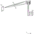
Fig. 2 illustrates an example of a wireless communication system 200 that supports power control in a directed beam environment in accordance with various aspects of the disclosure. In some examples, wireless communication system 200 may implement aspects of wireless communication system 100. The wireless communication system 200 may include a UE 115-a and a base station 105-a.
The wireless communication system 200 may include various processes that provide power control for the uplink and/or downlink. For example, these power control processes may include an open loop feedback component and a closed loop feedback component. The power control procedure may determine energy per resource element output by a transmitter (e.g., UE 115-a or base station 105-a) during a transmission (e.g., uplink or downlink).
In some cases, the base station 105-a may transmit uplink transmit power control commands to the UE 115-a using Downlink Control Information (DCI). In some cases, UE 115-a may transmit uplink signals on a link. For example, in carrier aggregation, the UE 115-a may simultaneously use different component carriers to transmit uplink signals. When different signals are transmitted simultaneously on different links, the uplink power control procedure may be configured to ensure that the total transmit power of the different signals does not exceed the maximum transmit power of the UE 115-a. Based on hardware, firmware, software, and/or other features, the UE 115-a may have an upper limit on how much transmit power can be output at a given time. For example, the power specification and antenna specification of the UE 115-a may limit the maximum total transmit power of the UE 115-a.
The wireless communication system 200 may be configured to establish a communication link between nodes (e.g., base station 105-a and UE 115-a) using a directional Beam Pair Link (BPL). The BPL may include a directional transmit beam formed by one entity (e.g., base station 105-a in the case of downlink) and a directional receive beam formed by another entity (e.g., UE 115-a in the case of downlink). Each directional beam may be defined by a plurality of characteristics including beam width, beam direction, beam transmit power, beam spectrum, and/or other characteristics.
In some cases, multiple BPLs may be established between the UE 115-a and the base station 105-a. In this case, the UE 115-a (and base station 105-a) may be configured with an uplink power control procedure that manages power on a per directional beam basis. Such beam-specific uplink power control procedures may be configured to allocate transmit power among multiple directional uplink transmission beams such that the aggregate total power transmitted by UE 115-a does not exceed or is unlikely to exceed some maximum threshold of the output power of UE 115-a. In some cases, the UE may not use multiple BPLs at the same time, so the UE does not necessarily need to allocate its total available power among the multiple BPLs. However, the UE may still need to determine some power control parameters on a beam-by-beam basis, and may additionally need to send one or more power headroom reports to indicate these parameters to other devices (e.g., base station 105-a).
For example, as part of at least two BPLs, the UE115-a may establish a first directional uplink transmission beam 205 and a second directional uplink transmission beam 210 with the base station 105-a. The power control procedure of UE115-a may be configured to allocate transmit power on a per beam basis. The power control process may also be configured to provide a power report on a per beam basis. For example, the power headroom report may be indexed based on the directional beam. In one example, two active beams are identified. When a power headroom report is provided, the report may indicate which beam is associated with it. This may be done by including a bit b (where b is 0 or 1) in the report. A "0" may indicate a first beam and a "1" may indicate a second beam. Alternatively, a bitmap b1b2 may be used, where 01 refers to the first beam, 10 refers to the second beam, and 11 refers to both (e.g., the same configuration may be applied to both beams).
It should be noted that: the active beam itself may be identified by a QCL table (or TCI table) in association with some measured reference signals (e.g., SSB or CSI-RS), although two directional uplink transmission beams are shown in fig. 2, in other examples any number of directional uplink transmission beams may be established between the UE115-a and the base station 105-a.
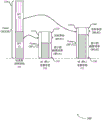
Fig. 3 illustrates an example of a power state 300 supporting power control in a directed beam environment, in accordance with various aspects of the present disclosure. In some examples, power state 300 may implement aspects of wireless communication systems 100 and/or 200. The power state 300 illustrates one or more power control procedures for allocating maximum transmit power among different directional beams and/or calculating power headroom parameters for the different directional beams. The power states 300 may include a total UE transmit power state 305, a first BPL transmit power state (BPL 1) 310, and a second transmit power state (BLP 2) 315. Although power states for two BPLs are shown, in other cases any number of beam-pair links may be established between a UE (e.g., UE 115) and a base station (e.g., base station 105).
The power allocation between beams may be based on a variety of factors. For example, as part of allocating transmit power among different directional beams, the UE 115 may identify a maximum output power 320 (also referred to as a maximum transmit power) of the UE 115, identify a number of beams or BPLs supported by the UE 115, and identify various characteristics (e.g., widths or directions) of the BPLs. The UE 115 may be configured such that each directional beam has independent Transmit Power Control (TPC).
As part of determining the maximum transmit power for each BPL, the UE 115 may be based on an upper bound (e.g., P CMAX,U ) And a lower limit (e.g., P CMAX,L ) To select the maximum output power 325, 330. In some cases, equation 1 may be used to determine the lower limit value:
P CMAX,L =min(P EMAX -ΔT C ,P powerclass -max(MPR+AMPR,PMPR)-ΔT C ) (1)
wherein P is EMAX May be the maximum power that the base station 105 can signal, Δt C There may be a decrease in the lower limit of maximum power when the signal approaches the channel edge (e.g., 4MHz at the channel edge), MPR may be a maximum power reduction margin, AMPR may be an additional MPR, and PMPR may be a power management MPR. MPR may be based at least in part on resource block allocation, modulation coding scheme, or a combination thereof. In some examples, the base station 105 may notify the UE 115 of the AMPR.
In some cases, the upper limit may be determined using equation 2:
P CMAX,U =min(P EMAX ,P powerclass ) (2)
the UE 115 may select a maximum output power 320 for itself that is limited by an upper limit and a lower limit. In some cases, the UE 115 may determine an upper limit and a lower limit of the maximum output power on a per beam basis. In these cases, the UE 115 may select the maximum output power 325, 330 based at least in part on a beam-specific upper limit, a beam-specific lower limit, a maximum output power of the UE 115, a number of beams or BPs supported by the UE 115, or a combination thereof.
In some cases, the power output of each BPL or uplink transmission beam (e.g., 205, 210) may be independently controlled. As a result, each beam may have an independent TPC. In this case, the maximum output power of each beam may not exceed the total maximum output power of the UE 115 (e.g., P CMAX,b ≤P TMAX ). However, in some cases, the aggregate total output power of the combined beams may exceed the total maximum output power (P TMAX ) (e.g., sigma) b P CMAX,b ≥P TMAX )。
To assist the base station 105 in managing communication resources, the UE 115 may provide a report (e.g., a power headroom report) to the base station 105. The power headroom report may be indexed for each individual directional beam (or BPL) of the communication link. The power headroom report may include a field specifying the maximum output power (e.g., power headroom parameters 335, 340), power headroom parameters, or a combination thereof for each beam.
The power headroom parameter may indicate the power requirement of a given directional uplink transmission beam based on traffic on the estimated beam. For example, the power headroom parameter 335 for the first BPL may be the difference between the maximum output power 325 allocated to the first BPL and the estimated transmit power 345 of the first BPL. The estimated transmit power 345 may be based on the amount of communication resources allocated for transmission (i.e., more allocated resources may result in higher estimated transmit power).
In some cases, the estimated transmit power 345 may exceed the maximum output power 325. In this case, the power headroom parameter 335 may be a negative value indicating that the UE 115 is required to transmit at a total power that it cannot support. In this case, the base station 105 may reduce the amount of resources used for the transmission. However, after reducing the resources, the UE 115 may still have other information to send because the original grant of speculative resources is based on the amount of information the UE 115 wants to send. The base station 105 may allocate additional communication resources (sometimes in a later grant of resources) to transmit all information that the UE 115 has buffered. The power headroom calculation for the second BPL may further include: a difference between the maximum output power 330 allocated to the second BPL and the estimated transmit power 350 of the second BPL is determined.
The power headroom parameters 335, 340 may be one of a plurality of types. For example, the first type of power headroom parameters 335, 340 may consider a Physical Uplink Shared Channel (PUSCH). In the second type, the power headroom parameters 335, 340 may consider PUSCH and Physical Uplink Control Channel (PUCCH). In some cases, the first type may be used because a consistent amount of communication resources may be allocated to the PUCCH, and thus, a variation in output power due to the PUCCH may be minimal. In a third type, the power headroom parameters 335, 340 may be actual power headroom parameters and/or actual power headroom reports based on communication resources allocated to the UE 115. In a fourth type, the power headroom parameters 335, 340 may be virtual power headroom parameters and/or virtual power headroom reports based on the assumption that a channel (e.g., PUSCH or PUCCH) exists. Any combination of these various types of power headroom parameters and/or power headroom reports is possible.
The power headroom report (which may include both the maximum output power 325, 330 and the power headroom parameters 335, 340 for each directional beam) may be transmitted using a MAC CE (see, e.g., message structure 500 described with reference to fig. 5). In some cases, the power headroom report may include a bitmap to indicate to which directional uplink transmission beam various parameters are directed. In some cases, the power headroom report may include: a flag for indicating whether the power headroom report is virtual. In some cases, the power headroom report may include: a flag for indicating whether the power headroom parameter includes PUCCH. In some cases, the power headroom report may indicate one or more of the various parameters of the power headroom report (e.g., type 1, 2, 3, or 4 described herein). The power headroom report may be sent on a subframe where the UE 115 has an uplink grant.
Fig. 4 illustrates an example of a communication scheme 400 supporting power control in a directed beam environment, in accordance with various aspects of the disclosure. In some examples, communication scheme 400 may implement aspects of wireless communication systems 100 and/or 200. Communication scheme 400 illustrates an example of a power control procedure based on individual directional beams. The communication scheme 400 includes functionality and communications related to the UE 115-b and the base station 105-b.
At block 405, the UE 115-b may identify one or more beam-specific power parameters for each directional uplink beam associated with the UE 115-b and the base station 105-b. The beam-specific power parameters may be indicative of the power characteristics of the individual beams. Examples of beam-specific power parameters may include maximum transmit power (e.g., maximum output power 325, 330 described with reference to fig. 3). Another example of a beam-specific power parameter may include a power headroom parameter (e.g., power headroom parameters 335, 340). Another example of a beam-specific power parameter may be an estimated transmit power (e.g., estimated transmit powers 345, 350).
At block 420, UE 115-b may generate a beam-specific report 425 including one or more beam-specific power parameters. In some cases, the beam-specific report 425 may include one or more power parameters for each directional uplink transmission beam of the UE 115-b and associated with the base station 105-b. The beam-specific report may include a bitmap that associates a particular set of data elements (e.g., power parameters) with a particular directional beam for as many directional beams as there are communication links between the UE 115-b and the base station 105-b. Beam-specific reporting 425 may be an example of a power headroom report.
A single beam-specific report 425 may include information regarding multiple directional beams of the communication link. For example, the beam-specific report 425 may include power parameters for the first BPL, the second BPL, and so on, for each BPL that is part of the communication link between the UE 115-b and the base station 105-b.
One of the BPL or directional uplink transmission beams may be used to send a beam-specific report 425. In some cases, the beam-specific report 425 transmitted using the first BPL may include information about the second BPL, where the beam-specific report 425 is not transmitted using the second BPL.
In some cases, UE 115-b may generate and transmit a second beam-specific report. The second beam-specific report may be embodied similarly to the first beam-specific report 425 described herein. In some cases, the second beam-specific report may be sent using a different BPL than the first beam-specific report 425. In some examples, the second beam-specific report may include power parameters and/or other information not found in the first beam-specific report 425. The UE 115-b may determine whether the first beam-specific report 425 includes all relevant information for the base station 105-b. If not, the UE 115-b may generate a second beam-specific report. The second beam-specific report may be sent using the same BPL as the first beam-specific report 425 or a different BPL may be used to send the second beam-specific report. In some cases, the second beam-specific report includes information about the BPL used to transmit the first beam-specific report 425. In some examples, the second beam-specific report may include beam-specific power parameters for the second BPL and/or other BPLs different from the first BPL used to transmit the first beam-specific report 425.
In some cases, the beam-specific report 425 may be sent using a MAC CE carried on PUSCH. In some cases, the beam-specific report 425 may be sent using a MAC CE carried on the PUCCH. In some cases, beam-specific reports 425 may be sent using UCI carried on PUCCH.
Performing the functions of block 420 and generating beam-specific reports 425 may be based on: UE 115-b identifies a trigger event for power parameter reporting at block 415. Examples of trigger events may include: establishing a second directed uplink beam (or second BPL, as the case may be) with the base station 105-b, determining that a signal quality parameter associated with at least one of the directed uplink beams (or BPLs) meets a threshold, determining that a path loss estimate for at least one of the directed uplink beams (or BPLs) meets the threshold, determining that a Received Signal Received Power (RSRP) for the directed uplink beam (or BPL) meets the threshold or varies significantly from a previous value, determining that a timer (e.g., a prohibit timer) has expired, receiving a message 410 sent by the base station 105-b requesting a beam-specific report 425, determining that a configured number of TPC commands implemented by the UE 115-b meets the threshold, or a combination thereof. Other criteria for triggering PHR may include: significant changes since the previous path loss measurement, a threshold time (e.g., PHR prohibit timer) has been exceeded, and the UE has implemented more than a selected number of TPC commands. In some cases, any of these factors may be determined on a beam-by-beam basis, may be determined for the entire UE, or may be determined for one or more subsets of directional beams (or BPLs). For example, the timer may be beam-specific. The base station 105-b may include functionality and/or components for identifying the conditions under which the message 410 was sent.
At block 430, the base station 105-b may identify one or more beam-specific power parameters for each directional uplink beam (or BPL) based on receiving the beam-specific report 425. The identification of the one or more beam-specific power parameters may be based on information included in the beam-specific report 425. The base station 105-b may identify which power parameters are used with which directional beam or BPL. Examples of the one or more beam-specific power parameters may include a maximum output power, a power headroom parameter, or a combination thereof.
In some cases, the base station 105-b may identify parameters for multiple beams in the beam-specific report 425. In some cases, the base station 105-b may identify the beam-specific power parameters for a different BPL than the BPL used to transmit the beam-specific report 425. The base station 105-b may associate the beam-specific power parameters with a particular directional beam or directional BPL using a bitmap of the beam-specific report 425.
In some cases, the base station 105-b may receive multiple beam-specific reports from the UE 115-b. In this case, the base station 105-b may identify the beam-specific power parameters for the beam based on each of the plurality of beam-specific reports received from the UE 115-b.
At block 435, the base station 105-b may determine or allocate one or more uplink communication resources for the UE 115-b to direct an uplink transmission beam (or BPL) based on the identified power parameter. For example, if the power headroom parameter is negative, the base station 105-b may allocate less communication resources to the UE 115-b for the transmission. In another example, if the power headroom parameter is positive (e.g., the UE 115-b has free capacity), the base station 105-b may adjust the data rate (up or down) of the transmission. In some cases, the base station 105-b may reallocate some or part of the communication resources for a particular directional beam of the UE 115-b to another beam or another UE 115.
The base station 105-b may use the beam-specific reports 425 to help efficiently allocate resources between the directional uplink transmission beams of the UE 115-b or between the communication links of different UEs 115. Once the base station 105-b has allocated its available uplink communication resources, the base station 105-b may send a resource grant 440 to the UE 115-b (and/or other UEs 115 that may also be affected), the resource grant 440 indicating various transmission parameters of the uplink transmission beam 445 for the UE 115-b transmission. These transmission parameters may include: the spectral resources to be used by directional uplink transmission beam 445, the time resources (e.g., frames, subframes, and/or slots) to be used by directional uplink transmission beam 445, the transmit power of directional uplink transmission beam 445, the data rate of directional uplink transmission beam 445, or a combination thereof.
Fig. 5 illustrates an example of a message structure 500 supporting power control in a directed beam environment, in accordance with various aspects of the disclosure. In some examples, message structure 500 may implement aspects of wireless communication systems 100 and/or 200. Message structure 500 shows an example of a beam-specific report that includes beam-specific power parameters.
The message structure 500 may include a maximum output power field 505-n for each directional beam indexed in the message structure 500 and a power headroom parameter field 510-n for each directional beam indexed in the message structure 500. In some cases, the message structure 500 may include only the maximum output power field 505-n or only the power headroom parameter field 510-n. However, in other cases, the message structure 500 may include two and/or other fields. In some cases, the message structure 500 may include eight bits of a single parameter dedicated to a single directional beam. In some cases, all eight bits may convey information about the power parameter. In other cases, some of these bits may be reserved bits for other types of information (e.g., flags or other control information). In other examples, other numbers of bits may be used.
In some cases, the message structure 500 may include a bitmap to indicate to which directional uplink transmission beam various parameters are directed. In some cases, the message structure 500 may include a flag to indicate whether a particular parameter is virtual or whether the entire message structure 500 is virtual. In some cases, the message structure 500 may include a flag to indicate whether the power headroom parameter includes a PUCCH.
In some cases, the power control procedure described herein may be implemented in scenarios other than a wireless communication link between the UE 115 and the base station 105. For example, the processes and functions described herein may be applied to backhaul or Integrated Access and Backhaul (IAB) scenarios. In such an example, a first base station (or relay station) may perform a power control procedure for a communication link established with a second base station (or relay station), where the first base station may employ UE functionality and the second base station may employ base station functionality. In other examples, the processes and functions described herein may be applied to a device-to-device (e.g., UE-to-UE) scenario. In such an example, a first UE may communicate with a second UE and may perform a power control procedure for the communication link. In such a D2D scenario, one of the UEs may act as a scheduler for the D2D link, while the other UE may act as a device that is served. In a D2D scenario, as described herein, any UE may employ the functionality of a base station in a power control procedure, and any UE may employ the functionality of a UE in a power control procedure.
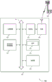
Fig. 6 illustrates a block diagram 600 of a wireless device 605 supporting power control in a directed beam environment, in accordance with aspects of the present disclosure. The wireless device 605 may be an example of some aspects of the UE 115 as described herein. The wireless device 605 may include a receiver 610, a UE power control manager 615, and a transmitter 620. The wireless device 605 may also include a processor. Each of these components may communicate with each other (e.g., via one or more buses).
The receiver 610 may receive information such as packets, user data, or control information associated with various information channels (e.g., control channels, data channels, and information related to power control in a directional beam environment, etc.). Information may be transferred to other components of the device. Receiver 610 may be an example of some aspects of transceiver 935 described with reference to fig. 9. The receiver 610 may utilize a single antenna or a set of antennas.
UE power control manager 615 may be an example of some aspects of UE power control managers 145 and 915 described with reference to fig. 1 and 9, respectively. At least some of the UE power control manager 615 and/or its various subcomponents may be implemented in hardware, software executed by a processor, firmware, or any combination thereof. When implemented in software executed by a processor, a general purpose processor, a Digital Signal Processor (DSP), an Application Specific Integrated Circuit (ASIC), a Field Programmable Gate Array (FPGA) or other Programmable Logic Device (PLD), discrete gate or transistor logic, discrete hardware components, or any combination thereof, used to perform the functions of at least some of the UE power control manager 615 and/or its various subcomponents may perform the functions described in this disclosure. The UE power control manager 615 and/or at least some of its various subcomponents may be physically distributed over multiple locations including being distributed as part of implementing functionality in different physical locations by one or more physical devices. In some examples, the UE power control manager 615 and/or at least some of its various subcomponents may be separate and distinct components in accordance with various aspects of the present disclosure. In other examples, at least some of the UE power control manager 615 and/or its various subcomponents may be combined with one or more other hardware components, including but not limited to: an I/O component, a transceiver, a web server, another computing device, one or more other components described in this disclosure, or a combination thereof.
The UE power control manager 615 may identify beam-specific parameters that indicate a maximum transmit power for a directional uplink beam of the UE, generate a beam-specific report that includes the beam-specific parameters, and send the beam-specific report using the directional uplink beam. The UE power control manager 615 may also perform various techniques for power control management described herein.
The transmitter 620 may transmit signals generated by other components of the device 605. In some examples, the transmitter 620 may be collocated with the receiver 610 in a transceiver module. For example, transmitter 620 may be an example of some aspects of transceiver 935 described with reference to fig. 9. The transmitter 620 may utilize a single antenna or may utilize a set of antennas.
Fig. 7 illustrates a block diagram 700 of a wireless device 705 supporting power control in a directed beam environment, in accordance with aspects of the present disclosure. The wireless device 705 may be an example of some aspect of the wireless device 605 or UE 115 as described herein with reference to fig. 6. The wireless device 705 may include a receiver 710, a UE power control manager 715, and a transmitter 720. The wireless device 705 may also include a processor. Each of these components may communicate with each other (e.g., via one or more buses).
The receiver 710 may receive information such as packets, user data, or control information associated with various information channels (e.g., control channels, data channels, and information related to power control in a directional beam environment, etc.). Information may be transferred to other components of the device. Receiver 710 may be an example of some aspects of transceiver 935 described with reference to fig. 9. The receiver 710 may utilize a single antenna or a set of antennas.
UE power control manager 715 may be an example of some aspects of UE power control manager 915 as described with reference to fig. 9. The UE power control manager 715 may also include a parameter manager 725, a report manager 730, and a directional link manager 735.
The parameter manager 725 may identify one or more parameters or power settings and/or allocations. For example, the parameter manager 725 may identify beam-specific parameters that indicate a maximum transmit power for a directional uplink beam of the UE or a second beam-specific parameter for a second directional uplink beam of the UE. The parameter manager 725 may identify a maximum transmit power for the second directional uplink beam, where the second beam-specific parameter indicates the identified maximum transmit power for the second directional uplink beam. The parameter manager 725 may also A second beam-specific parameter for steering the uplink beam is identified, wherein the second beam-specific parameter indicates a difference between a maximum transmit power and an estimated transmit power for steering the uplink beam, wherein the beam-specific report includes the second beam-specific parameter. In some cases, the beam-specific parameter is P CMAX Parameters. In some examples, P will be CMAX The parameters are transmitted together with the PHR in the same MAC CE and in a bitmap indicating which Secondary Component Carrier (SCC) the information corresponds to. In some examples, a flag may indicate P CMAX Whether the parameter is virtual. In some cases, the second beam-specific parameter is a power headroom parameter.
The directional link manager 735 may send the beam-specific report using the directional uplink beam, send the beam-specific report with the second beam-specific parameter and the beam-specific parameter using the directional uplink beam, and send the second beam-specific report using the directional uplink beam or the second directional uplink beam. In some cases, the second beam-specific report is sent using MACCE carried on PUSCH or UCI carried on PUCCH, or a combination thereof. In some cases, the beam-specific report is sent using a MAC CE carried on PUSCH on the first uplink beam or UCI carried on PUCCH on the first uplink beam, or a combination thereof.
Fig. 8 illustrates a block diagram 800 of a UE power control manager 815 supporting power control in a directional beam environment, in accordance with aspects of the disclosure. UE power control manager 815 may be an example of some aspect of UE power control manager 615, 715, or 915 described with reference to fig. 6, 7, and 9. UE power control manager 815 may include a parameter manager 825, a report manager 830, a directional link manager 835, a power headroom manager 840, a bitmap manager 845, and a trigger manager 850. Each of these modules may communicate directly or indirectly with each other (e.g., via one or more buses).
The report manager 830 can generate a beam-specific report including the beam-specific parameters and generate a second beam-specific report, wherein the second beam-specific report includes the second beam-specific parameters for the second directional uplink beam. In some cases, the beam-specific report is a power headroom report, wherein the power headroom report includes power information for a set of directional uplink beams associated with the UE.
The directional link manager 835 may transmit a beam-specific report using a directional uplink beam, transmit a beam-specific report having a second beam-specific parameter and the beam-specific parameter using the directional uplink beam, and transmit the second beam-specific report using the directional uplink beam or the second directional uplink beam. In some cases, the beam-specific report and/or the second beam-specific report is transmitted using a medium access control, MAC, CE, carried on PUSCH or UCI carried on PUCCH, or a combination thereof. In some cases, PUSCH and/or PUCCH may be on the first directional uplink beam.
The power headroom manager 840 may identify a difference between the maximum transmit power for the second directional uplink beam and the estimated transmit power for the second directional uplink beam, wherein the second beam-specific parameter indicates the identified difference.
The bitmap manager 845 can generate a bitmap that associates a first set of data elements of the beam-specific report with beam-specific parameters with a second set of data elements of the beam-specific report with second beam-specific parameters.
The trigger manager 850 can identify a trigger event associated with directing the uplink beam, wherein generating the beam-specific report is based on identifying the trigger event. In some cases, the trigger event includes at least one of: establishing a second directional uplink beam with the base station, or determining that a signal quality parameter associated with the directional uplink beam meets a threshold, or determining that a timer associated with the directional uplink beam has expired, or receiving a message requesting reception of a beam-specific report, or a combination thereof.
Fig. 9 illustrates a diagram of a system 900 that includes a device 905, wherein the device 905 supports power control in a directional beam environment, in accordance with aspects of the present disclosure. The device 905 may be, or include components of, an example of the wireless device 605, the wireless device 705, or the UE 115 as described above, for example, with reference to fig. 6 and 7. The device 905 may comprise means for two-way voice and data communications, including means for transmitting communications and means for receiving communications, including a UE power control manager 915, a processor 920, memory 925, software 930, a transceiver 935, an antenna 940, and an I/O controller 945. These components may be in electrical communication via one or more buses (e.g., bus 910). The device 905 may communicate wirelessly with one or more base stations 105.
The processor 920 may include intelligent hardware devices (e.g., general purpose processors, DSPs, central Processing Units (CPUs), microcontrollers, ASICs, FPGAs, programmable logic devices, split gate or transistor logic elements, split hardware elements, or any combinations thereof). In some cases, processor 920 may be configured to operate a memory array using a memory controller. In other cases, the memory controller may be integrated into the processor 920. The processor 920 may be configured to execute computer-readable instructions stored in memory to perform various functions (e.g., functions or tasks to support power control in a directed beam environment).
The memory 925 may include Random Access Memory (RAM) and Read Only Memory (ROM). The memory 925 may store computer-readable, computer-executable software 930 including instructions that, when executed, cause the processor to perform the various functions described herein. In some cases, in particular, the memory 925 may contain a basic input/output system (BIOS), which may control basic hardware or software operations (e.g., interactions with peripheral components or devices).
In some cases, the wireless device 905 may include a single antenna 940. However, in some cases, the device 905 may have more than one antenna 940, the antennas 940 being capable of sending or receiving multiple wireless transmissions simultaneously.
The I/O controller 945 may manage input and output signals for the device 905. The I/O controller 945 may also manage peripheral devices that are not integrated into the device 905. In some cases, the I/O controller 945 may represent a physical connection or port for an external peripheral device. In some cases, I/O controller 945 may utilize a controller such as, for example  MS-/>
MS-/> MS-/>
MS-/> Such as an operating system or another known operating system. In other cases, the I/
O controller 945 may represent or interact with a modem, keyboard, mouse, touch screen, or similar device. In some cases, the I/O controller 945 may be implemented as part of a processor. In some cases, a user may interact with the device 905 via the I/O controller 945 or via hardware components controlled by the I/O controller 945. />
Fig. 10 illustrates a block diagram 1000 of a wireless device 1005 supporting power control in a directed beam environment, in accordance with aspects of the present disclosure. The wireless device 1005 may be an example of some aspects of the base station 105 as described herein. The wireless device 1005 may include a receiver 1010, a base station power control manager 1015, and a transmitter 1020. The wireless device 1005 may also include a processor. Each of these components may communicate with each other (e.g., via one or more buses).
The receiver 1010 may receive information such as packets, user data, or control information associated with various information channels (e.g., control channels, data channels, and information related to power control in a directional beam environment, etc.). Information may be transferred to other components of the device 1005. The receiver 1010 may be an example of some aspects of the transceiver 1335 described with reference to fig. 13. The receiver 1010 may utilize a single antenna or a set of antennas.
Base station power control manager 1015 may be an example of some aspects of base station power control managers 140 and 1315 described with reference to fig. 1 and 13, respectively. At least some of the base station power control manager 1015 and/or its various subcomponents may be implemented in hardware, software executed by a processor, firmware, or any combination thereof. When implemented in software executed by a processor, a general purpose processor, DSP, ASIC, FPGA or other programmable logic device, discrete gate or transistor logic device, discrete hardware components, or any combination thereof, for performing the functions described in this disclosure may perform the functions of at least some of the base station power control manager 1015 and/or its various subcomponents. The base station power control manager 1015 and/or at least some of its various subcomponents may be physically distributed over multiple locations including being distributed as part of implementing functionality in different physical locations by one or more physical devices. In some examples, the base station power control manager 1015 and/or at least some of its various subcomponents may be separate and distinct components in accordance with various aspects of the present disclosure. In other examples, at least some of the base station power control manager 1015 and/or its various subcomponents may be combined with one or more other hardware components, including but not limited to: an I/O component, a transceiver, a web server, another computing device, one or more other components described in this disclosure, or a combination thereof.
The base station power control manager 1015 may receive the beam-specific reports transmitted by the UE using the directional uplink beams, identify beam-specific parameters indicating a maximum transmit power for the directional uplink beams based on the received beam-specific reports, determine one or more uplink communication resources for the UE based on the beam-specific parameters, and transmit a message indicating a grant of resources to the UE based on the one or more uplink communication resources.
Fig. 11 illustrates a block diagram 1100 of a wireless device 1105 supporting power control in a directed beam environment in accordance with aspects of the disclosure. The wireless device 1105 may be an example of some aspect of the wireless device 1005 or base station 105 as described with reference to fig. 10. The wireless device 1105 may include a receiver 1110, a base station power control manager 1115, and a transmitter 1120. The wireless device 1105 may also include a processor. Each of these components may communicate with each other (e.g., via one or more buses).
The receiver 1110 may receive information such as packets, user data, or control information associated with various information channels (e.g., control channels, data channels, and information related to power control in a directional beam environment, etc.). Information may be transferred to other components of the device. Receiver 1110 may be an example of some aspects of transceiver 1335 described with reference to fig. 13. The receiver 1110 may utilize a single antenna or a set of antennas.
Base station power control manager 1115 may be an example of some aspects of base station power control manager 1315 as described with reference to fig. 13. The base station power control manager 1115 may also include a directional link manager 1125, a parameter manager 1130, and a resource manager 1135.
The directional link manager 1125 may receive a beam-specific report transmitted by the UE using the directional uplink beam, transmit a message indicating resource grant to the UE based on the one or more uplink communication resources, and transmit a second message to the UE requesting the beam-specific report, wherein receiving the beam-specific report is based at least in part on the second message being transmitted.
The parameter manager 1130 may identify one or more parameters or power settings and/or assignments. For example, the parameter manager 1130 may identify a beam-specific parameter indicating a maximum transmit power for the directed uplink beam based on receiving the beam-specific report, or identify a second beam-specific parameter for a second directed uplink beam of the UE based on receiving the beam-specific report, wherein the beam-specific report received using the directed uplink beam includes the second beam-specific parameter for the second directed uplink beam. In other examples, parameter manager 1130 may identify a maximum transmit power for the second directional uplink beam based on the beam-specific report, wherein the second beam-specific parameter indicates the maximum transmit power for the second directional uplink beam. The parameter manager 1130 may identify a second beam-specific parameter for the third directional uplink beam based on the second beam-specific report, wherein determining the one or more uplink communication resources is based on the second beam-specific parameter for the third directional uplink beam. In other examples, parameter manager 1130 may identify a second beam-specific parameter for the directional uplink beam, where the second beam-specific parameter indicates a maximum transmit power and a maximum transmit power for the directional uplink beam A difference between the transmit powers is estimated, wherein the beam-specific report includes a second beam-specific parameter. In some cases, the second beam-specific report is transmitted using a Medium Access Control (MAC) Control Element (CE) carried on PUSCH or Uplink Control Information (UCI) carried on PUCCH, or a combination thereof. In some cases, the beam-specific report is sent using a MAC CE carried on PUSCH on the first uplink beam or UCI carried on PUCCH on the first uplink beam, or a combination thereof. In some cases, the beam-specific parameter is P CMAX Parameters. In some cases, the second beam-specific parameter is a power headroom parameter.
The resource manager 1135 may determine one or more uplink communication resources for the UE based on the beam-specific parameters.
The transmitter 1120 may transmit signals generated by other components of the device 1105. In some examples, transmitter 1120 may be collocated with receiver 1110 in a transceiver module. For example, the transmitter 1120 may be an example of some aspects of the transceiver 1335 described with reference to fig. 13. Transmitter 1120 may utilize a single antenna or may utilize a set of antennas.
Fig. 12 illustrates a block diagram 1200 of a base station power control manager 1215 supporting power control in a directed beam environment, in accordance with aspects of the subject disclosure. Base station power control manager 1215 may be an example of some aspects of base station power control manager 1315 described with reference to fig. 10, 11, and 13. Base station power control manager 1215 may include a directional link manager 1220, a parameter manager 1225, a resource manager 1230, a power headroom manager 1235, and a report manager 1240. Each of these modules may communicate directly or indirectly with each other (e.g., via one or more buses).
The directional link manager 1220 may receive a beam-specific report sent by the UE using the directional uplink beam, send a message indicating resource grant to the UE based on the one or more uplink communication resources, and send a second message requesting the beam-specific report to the UE, wherein receiving the beam-specific report is based at least in part on sending the second message.
The parameter manager 1225 may identify a beam-specific parameter indicative of a maximum transmit power for the directed uplink beam based on receiving the beam-specific report, identify a second beam-specific parameter for the second directed uplink beam for the UE based on receiving the beam-specific report, wherein the beam-specific report received using the directed uplink beam includes the second beam-specific parameter for the second directed uplink beam, identify the maximum transmit power for the second directed uplink beam based on the beam-specific report, wherein the second beam-specific parameter is indicative of the maximum transmit power for the second directed uplink beam, identify the second beam-specific parameter for the third directed uplink beam based on the second beam-specific report, wherein determining the one or more uplink communication resources is based on the second beam-specific parameter for the third directed uplink beam, and identify the second beam-specific parameter for the directed uplink beam, wherein the second beam-specific parameter is indicative of a difference between the maximum transmit power for the second directed uplink beam and the report, wherein the determining the one or more uplink communication resources includes the difference between the beam-specific parameters. In some cases, the second beam-specific report is sent using a MAC CE carried on PUSCH or UCI carried on PUCCH, or a combination thereof. In some cases, the beam-specific report is sent using a MAC CE carried on PUSCH on the first uplink beam or UCI carried on PUCCH on the first uplink beam, or a combination thereof. In some cases, the beam-specific parameter is P CMAX Parameters. In some cases, the second beam-specific parameter is a power headroom parameter.
The resource manager 1230 may determine one or more uplink communication resources for the UE based on the beam-specific parameters.
The power headroom manager 1235 can identify a difference between the maximum transmit power and the estimated transmit power for the second directional uplink beam based on the beam-specific report, wherein the second beam-specific parameter indicates the difference for the second directional transmit beam.
The report manager 1240 may receive a second beam-specific report using the directional uplink beam or a second directional uplink beam, wherein the second beam-specific report includes a second beam-specific parameter for a third directional uplink beam. In some cases, the beam-specific report is a power headroom report including power information for a set of directional uplink beams associated with the UE.
Fig. 13 illustrates a diagram of a system 1300 that includes a device 1305, wherein the device 1305 supports power control in a directional beam environment, in accordance with aspects of the present disclosure. Device 1305 may be an example of base station 105, as described above, for example, with reference to fig. 1, or a component comprising such devices. Device 1305 may include means for bi-directional voice and data communications including means for transmitting and means for receiving communications including a base station power control manager 1315, a processor 1320, memory 1325, software 1330, a transceiver 1335, an antenna 1340, a network communication manager 1345, and an inter-station communication manager 1350. These components may be in electrical communication via one or more buses (e.g., bus 1310). Device 1305 may communicate wirelessly with one or more UEs 115.
The transceiver 1335 may communicate bi-directionally via one or more antennas, wired links, or wireless links, as described above. For example, transceiver 1335 may represent a wireless transceiver that may communicate bi-directionally with another wireless transceiver. The transceiver 1335 may also include a modem to modulate packets, provide the modulated packets to an antenna for transmission, and demodulate packets received from the antenna.
In some cases, the wireless device 1305 may include a single antenna 1340. However, in some cases, the device 1305 may have more than one antenna 1340, and these antennas 1340 may be capable of sending or receiving multiple wireless transmissions simultaneously.
The network communication manager 1345 may manage communication with the core network (e.g., via one or more wired backhaul links). For example, the network communication manager 1345 may manage the transmission of data communications for a client device (e.g., one or more UEs 115).
The inter-station communication manager 1350 may manage communications with other base stations 105 and may include a controller or scheduler for controlling communications with UEs 115 in cooperation with other base stations 105. For example, inter-station communication manager 1350 may coordinate scheduling of transmissions for UEs 115 to implement various interference mitigation techniques such as beamforming or joint transmission. In some examples, inter-station communication manager 1350 may provide an X2 interface in LTE/LTE-a wireless communication network technology to provide communication between base stations 105.
Fig. 14 illustrates a flow chart of a method 1400 for power control in a directed beam environment, in accordance with aspects of the present disclosure. The operations of the method 1400 may be implemented by the UE 115 or components thereof as described herein. For example, the operations of method 1400 may be performed by a UE power control manager as described with reference to fig. 6-9. In some examples, UE 115 may execute a set of codes to control the functional units of the device to perform the functions described below. Additionally or alternatively, UE 115 may perform aspects of the functions described below using special purpose hardware.
At 1405, UE 115 may identify a beam-specific parameter that indicates a maximum transmit power for the UE's directional uplink beam. Operations of 1405 may be performed according to the methods described herein. In some examples, aspects of the operation of 1405 may be performed by a parameter manager as described with reference to fig. 6-9.
At 1410, UE 115 may generate a beam-specific report including the beam-specific parameters. The operations of 1410 may be performed according to the methods described herein. In some examples, aspects of the operation of 1410 may be performed by a report manager as described with reference to fig. 6-9.
At 1415, UE 115 may use the directional uplink beam to transmit a beam-specific report. Operations of 1415 may be performed according to the methods described herein. In some examples, aspects of the operation of 1415 may be performed by a directional link manager as described with reference to fig. 6-9.
Fig. 15 illustrates a flow chart of a method 1500 for power control in a directed beam environment in accordance with aspects of the disclosure. The operations of method 1500 may be implemented by base station 105 or components thereof as described herein. For example, the operations of method 1500 may be performed by a base station power control manager as described with reference to fig. 10-13. In some examples, the base station 105 may execute a set of codes to control the functional units of the device to perform the functions described below. Additionally or alternatively, the base station 105 may perform aspects of the functions described below using special purpose hardware.
At 1505, the base station 105 may receive a beam-specific report sent by the UE using the directional uplink beam. The operations of 1505 may be performed according to the methods described herein. In some examples, aspects of the operation of 1505 may be performed by a directional link manager as described with reference to fig. 10-13.
At 1510, the base station 105 can identify a beam-specific parameter indicating a maximum transmit power for the directional uplink beam based at least in part on receiving the beam-specific report. The operations of 1510 may be performed according to the methods described herein. In some examples, the operations of 1510 may be performed by a parameter manager as described with reference to fig. 10-13.
At 1515, the base station 105 may determine one or more uplink communication resources for the UE based at least in part on the beam-specific parameters. The operations of 1515 may be performed according to methods described herein. In some examples, the operations of 1515 may be performed by a resource manager as described with reference to fig. 10-13.
At 1520, the base station 105 can send a message to the UE indicating the grant of resources based at least in part on the one or more uplink communication resources. Operations of 1520 may be performed according to the methods described herein. In some examples, the operations of 1520 may be performed by a directional link manager as described with reference to fig. 10-13.
It should be noted that the above-described method describes possible implementations, and that these operations and steps may be rearranged or modified, as well as other implementations are possible. Furthermore, aspects from two or more of these methods may be combined.
The techniques described herein may be used for various wireless communication systems such as Code Division Multiple Access (CDMA), time Division Multiple Access (TDMA), frequency Division Multiple Access (FDMA), orthogonal Frequency Division Multiple Access (OFDMA), single carrier frequency division multiple access (SC-FDMA), and other systems. A CDMA system may implement a radio technology such as CDMA2000, universal Terrestrial Radio Access (UTRA), and so on. CDMA2000 covers IS-2000, IS-95 and IS-856 standards. IS-2000 release IS commonly referred to as CDMA2000 1X, and so on. IS-856 (TIA-856) IS commonly referred to as CDMA 20001xEV-DO, high Rate Packet Data (HRPD), and so forth. UTRA includes Wideband CDMA (WCDMA) and other CDMA variants. TDMA systems may implement radio technologies such as global system for mobile communications (GSM).
OFDMA systems may implement radio technologies such as Ultra Mobile Broadband (UMB), evolved UTRA (E-UTRA), institute of Electrical and Electronics Engineers (IEEE) 802.11 (Wi-Fi), IEEE 802.16 (WiMAX), IEEE 802.20, flash-OFDM, and so forth. UTRA and E-UTRA are part of Universal Mobile Telecommunications System (UMTS). LTE and LTE-a are versions of UMTS that employ E-UTRA. UTRA, E-UTRA, UMTS, LTE, LTE-A, NR and GSM are described in documents from an organization named "third generation partnership project" (3 GPP). CDMA2000 and UMB are described in documents from an organization named "third generation partnership project 2" (3 GPP 2). The techniques described herein may be used for the systems and radio technologies mentioned above and other systems and radio technologies. Although aspects of the LTE or NR system are described for purposes of example and LTE or NR terminology is used in much of the description, the techniques described herein may also be applicable beyond LTE or NR applications.
A macrocell typically covers a relatively large geographic area (e.g., a few kilometers in radius) that allows unrestricted access by UEs 115 with service subscription with the network provider. A small cell may be associated with the low power base station 105 as compared to a macro cell, which may operate in the same or different (e.g., licensed, unlicensed, etc.) frequency band as the macro cell. According to various examples, small cells may include pico cells, femto cells, and micro cells. For example, a pico cell may cover a relatively small geographic area that allows unrestricted access by UEs 115 with service subscription with the network provider. A femto cell may also cover a smaller geographic area (e.g., a home) that may provide restricted access to UEs 115 (e.g., UEs in a Closed Subscriber Group (CSG), UEs for users in the home, etc.) that have an association with the femto cell. An eNB for a macro cell may be referred to as a macro eNB. An eNB for a small cell may be referred to as a small cell eNB, a pico eNB, a femto eNB, or a home eNB. An eNB may support one or more (e.g., two, three, four, etc.) cells and may also support communication using one or more component carriers.
The wireless communication system 100 or set of systems described herein may support synchronous or asynchronous operation. For synchronous operation, the base stations 105 may have similar frame timing with transmissions from different base stations 105 approximately aligned in time. For asynchronous operation, the base stations 105 may have different frame timing, with transmissions from different base stations 105 not aligned in time. The techniques described herein may be used for synchronous operation as well as asynchronous operation.
The information and signals described herein may be represented using any of a variety of different technologies and techniques. For example, data, instructions, commands, information, signals, bits, symbols, and chips that may be referenced throughout the above description may be represented by voltages, currents, electromagnetic waves, magnetic fields or particles, optical fields or particles, or any combination thereof.
A general purpose processor, DSP, ASIC, FPGA or other PLD, discrete gate or transistor logic, discrete hardware components, or any combination thereof, used to perform the functions described herein can be used to implement or perform the various exemplary blocks and modules described in connection with the disclosure herein. A general purpose processor may be a microprocessor, but in the alternative, the processor may be any conventional processor, controller, microcontroller, or state machine. A processor may also be implemented as a combination of computing devices (e.g., a combination of a DSP and a microprocessor, a plurality of microprocessors, a combination of a microprocessor and a DSP core, or any other such configuration).
The functions described herein may be implemented in hardware, software executed by a processor, firmware, or any combination thereof. When implemented in software executed by a processor, these functions may be stored on a computer-readable medium or transmitted as one or more instructions or code on a computer-readable medium. Other examples and implementations are within the scope of the present disclosure and the appended claims. For example, due to the nature of software, the functions described above may be implemented using software executed by a processor, hardware, firmware, hardware wiring, or any combination thereof. Features that are used to implement a function may be physically distributed over several locations including being distributed over different physical locations to implement a portion of the function.
Computer-readable media includes both non-transitory computer storage media and communication media including any medium that facilitates transfer of a computer program from one place to another. Non-transitory storage media may be any available media that can be accessed by a general purpose or special purpose computer. By way of example, and not limitation, non-transitory computer-readable media may comprise RAM, ROM, electrically erasable programmable read-only memory (EEPROM), flash memory, compact Disk (CD) ROM or other optical disk storage, magnetic disk storage or other magnetic storage devices, or any other non-transitory medium that can be used to carry or store desired program code means in the form of instructions or data structures and that can be accessed by a general-purpose or special-purpose computer, or a general-purpose or special-purpose processor. Further, any connection is properly termed a computer-readable medium. For example, if the software is transmitted from a website, server, or other remote source using a coaxial cable, fiber optic cable, twisted pair, digital Subscriber Line (DSL), or wireless technologies such as infrared, radio, and microwave, then the coaxial cable, fiber optic cable, twisted pair, DSL, or wireless technologies such as infrared, radio, and microwave are included in the definition of medium. Disk and disc, as used herein, includes CD, laser disc, optical disc, digital Versatile Disc (DVD), floppy disk and blu-ray disc where disks usually reproduce data magnetically, while discs reproduce data optically with lasers. Combinations of the above should also be included within the scope of computer-readable media.
As used herein (including in the claims), an "or" (e.g., a list item ending with a phrase such as "at least one of" or "one or more of") as used in the list item indicates an inclusive list, such that, for example, a list of at least one of A, B or C means a or B or C or AB or AC or BC or ABC (i.e., a and B and C). Furthermore, as used herein, the phrase "based on" should not be construed as referring to a closed set of conditions. For example, exemplary steps described as "based on condition a" may be based on condition a and condition B without departing from the scope of the present disclosure. In other words, as used herein, the phrase "based on" should be interpreted in the same manner as the phrase "based at least in part on" based on.
In the drawings, like parts or features have the same reference numerals. Furthermore, the respective components of the same type may be distinguished by following the reference label by a broken line and a second label for distinguishing the similar components. If only the first reference label is used in the specification, the description may be applied to any one of the similar components having the same first reference label, regardless of the other subsequent reference label.
The detailed description set forth herein in connection with the appended drawings describes an exemplary configuration, but is not intended to represent all examples that may be implemented, nor are they intended to represent all examples that fall within the scope of the claims. The term "exemplary" as used herein means "serving as an example, instance, or illustration," but does not mean "preferred" or "advantageous" over other examples. The detailed description includes specific details for providing a thorough understanding of the described technology. However, the techniques may be practiced without these specific details. In some instances, well-known structures and devices are shown in block diagram form in order to avoid obscuring the concepts of the described examples.
The previous description is provided to enable any person skilled in the art to make or use the present disclosure. Various modifications to the disclosure will be readily apparent to those skilled in the art, and the generic principles defined herein may be applied to other variations without departing from the scope of the disclosure. Thus, the disclosure is not intended to be limited to the examples and designs described herein but is to be accorded the widest scope consistent with the principles and novel features disclosed herein.
Claims (42)
1. A method for wireless communication, comprising:
identifying a beam-specific parameter, wherein the beam-specific parameter indicates a maximum transmit power for a directional uplink beam of a User Equipment (UE);
identifying a trigger event associated with the directional uplink beam, wherein the trigger event comprises a determination that a beam-specific timer for the directional uplink beam has expired;
based at least in part on identifying the trigger event, generating a beam-specific report including the beam-specific parameter indicating the maximum transmit power for the directional uplink beam; and
the beam-specific report is sent using the directional uplink beam.
2. The method of claim 1, further comprising:
identifying a second beam-specific parameter for a second directional uplink beam of the UE; and
using the directional uplink beam, sending the beam-specific report with the second beam-specific parameter and the beam-specific parameter.
3. The method of claim 2, further comprising:
A maximum transmit power for the second directional uplink beam is identified, wherein the second beam-specific parameter indicates the identified maximum transmit power for the second directional uplink beam.
4. The method of claim 2, further comprising:
a difference between a maximum transmit power for the second directional uplink beam and an estimated transmit power for the second directional uplink beam is identified, wherein the second beam-specific parameter indicates the identified difference.
5. The method of claim 2, further comprising:
generating a bitmap associating a first set of data elements of the beam-specific report having the beam-specific parameter with a second set of data elements of the beam-specific report having the second beam-specific parameter.
6. The method of claim 2, further comprising:
estimating traffic for the second directional uplink beam, wherein the second beam-specific parameter indicates a power requirement of the second directional uplink beam based at least in part on the estimated traffic.
7. The method of claim 1, further comprising:
generating a second beam-specific report comprising a second beam-specific parameter for a second directional uplink beam; and
the second beam-specific report is sent using the directional uplink beam or the second directional uplink beam.
8. The method of claim 7, wherein the second beam-specific report is transmitted using a Medium Access Control (MAC) Control Element (CE) carried on a Physical Uplink Shared Channel (PUSCH) or Uplink Control Information (UCI) carried on a Physical Uplink Control Channel (PUCCH), or a combination thereof.
9. The method of claim 1, wherein the beam-specific report is transmitted using a Medium Access Control (MAC) Control Element (CE) carried on a Physical Uplink Shared Channel (PUSCH) on a first uplink beam or Uplink Control Information (UCI) carried on a Physical Uplink Control Channel (PUCCH) on the first uplink beam, or a combination thereof.
10. The method of claim 1, wherein the triggering event further comprises at least one of: establishing a second directional uplink beam with the base station, or determining that a signal quality parameter associated with the directional uplink beam meets a threshold, or receiving a message requesting reception of the beam-specific report, or a combination thereof.
11. The method of claim 1, further comprising:
a second beam-specific parameter for the directional uplink beam is identified, the second beam-specific parameter indicating a difference between the maximum transmit power and an estimated transmit power for the directional uplink beam, wherein the beam-specific report includes the second beam-specific parameter.
12. The method according to claim 11, wherein:
the beam-specific parameter is a PCMAX parameter; and
the second beam-specific parameter is a power headroom parameter.
13. The method of claim 1, wherein the beam-specific report is a power headroom report, wherein the power headroom report includes power information for a plurality of directional uplink beams associated with the UE.
14. The method of claim 1, wherein the beam-specific report further comprises one or more additional power parameters for each additional directional uplink transmission beam of the UE.
15. A method for wireless communication, comprising:
receiving a beam-specific report transmitted by a User Equipment (UE) using a directional uplink beam, wherein the beam-specific report is generated based at least in part on the UE identifying a trigger event associated with the directional uplink beam, wherein the trigger event includes a determination that a beam-specific timer for the directional uplink beam has expired;
identifying a beam-specific parameter indicative of a maximum transmit power for the directional uplink beam based at least in part on receiving the beam-specific report;
determining one or more uplink communication resources for the UE based at least in part on the beam-specific parameters; and
a message indicating a resource grant is sent to the UE based at least in part on the one or more uplink communication resources.
16. The method of claim 15, further comprising:
A second beam-specific parameter of a second directed uplink beam for the UE is identified based at least in part on receiving the beam-specific report, wherein the beam-specific report received using the directed uplink beam includes the second beam-specific parameter for the second directed uplink beam.
17. The method of claim 16, further comprising:
a maximum transmit power for the second directional uplink beam is identified based at least in part on the beam-specific report, wherein the second beam-specific parameter indicates the maximum transmit power for the second directional uplink beam.
18. The method of claim 17, further comprising:
a difference between a maximum transmit power and an estimated transmit power for the second directional uplink beam is identified based at least in part on the beam-specific report, wherein the second beam-specific parameter indicates the difference for the second directional uplink beam.
19. The method of claim 15, further comprising:
receiving a second beam-specific report using the directional uplink beam or a second directional uplink beam, wherein the second beam-specific report includes a second beam-specific parameter for a third directional uplink beam; and
The method further includes identifying, based at least in part on the second beam-specific report, the second beam-specific parameter for the third directional uplink beam, wherein determining the one or more uplink communication resources is based at least in part on the second beam-specific parameter for the third directional uplink beam.
20. The method of claim 19, wherein the second beam-specific report is transmitted using a Medium Access Control (MAC) Control Element (CE) carried on a Physical Uplink Shared Channel (PUSCH) or Uplink Control Information (UCI) carried on a Physical Uplink Control Channel (PUCCH), or a combination thereof.
21. The method of claim 15, wherein the beam-specific report is transmitted using a Medium Access Control (MAC) Control Element (CE) carried on a Physical Uplink Shared Channel (PUSCH) on a first uplink beam or Uplink Control Information (UCI) carried on a Physical Uplink Control Channel (PUCCH) on the first uplink beam, or a combination thereof.
22. The method of claim 15, further comprising:
a second beam-specific parameter for the directional uplink beam is identified, the second beam-specific parameter indicating a difference between the maximum transmit power and an estimated transmit power for the directional uplink beam, wherein the beam-specific report includes the second beam-specific parameter.
23. The method according to claim 22, wherein:
the beam-specific parameter is a PCMAX parameter; and
the second beam-specific parameter is a power headroom parameter.
24. The method of claim 15, wherein the beam-specific report is a power headroom report, wherein the power headroom report includes power information for a plurality of directional uplink beams associated with the UE.
25. The method of claim 15, further comprising:
transmitting a second message to the UE requesting the beam-specific report, wherein receiving the beam-specific report is based at least on transmitting the second message.
26. An apparatus for wireless communication, comprising:
a processor;
a memory coupled to the processor; and
Instructions stored in the memory and executable by the processor to cause the apparatus to:
identifying a beam-specific parameter, wherein the beam-specific parameter indicates a maximum transmit power for a directional uplink beam of a User Equipment (UE);
identifying a trigger event associated with the directional uplink beam, wherein the trigger event comprises a determination that a beam-specific timer for the directional uplink beam has expired;
based at least in part on identifying the trigger event, generating a beam-specific report including the beam-specific parameter indicating the maximum transmit power for the directional uplink beam; and
the beam-specific report is sent using the directional uplink beam.
27. The apparatus of claim 26, wherein the instructions are further executable by the processor to cause the apparatus to:
identifying a second beam-specific parameter for a second directional uplink beam of the UE; and
using the directional uplink beam, sending the beam-specific report with the second beam-specific parameter and the beam-specific parameter.
28. The apparatus of claim 27, wherein the instructions are further executable by the processor to cause the apparatus to:
a maximum transmit power for the second directional uplink beam is identified, wherein the second beam-specific parameter indicates the identified maximum transmit power for the second directional uplink beam.
29. The apparatus of claim 27, wherein the instructions are further executable by the processor to cause the apparatus to:
a difference between a maximum transmit power for the second directional uplink beam and an estimated transmit power for the second directional uplink beam is identified, wherein the second beam-specific parameter indicates the identified difference.
30. The apparatus of claim 27, wherein the instructions are further executable by the processor to cause the apparatus to:
generating a bitmap associating a first set of data elements of the beam-specific report having the beam-specific parameter with a second set of data elements of the beam-specific report having the second beam-specific parameter.
31. The apparatus of claim 27, wherein the instructions are further executable by the processor to cause the apparatus to:
estimating traffic for the second directional uplink beam, wherein the second beam-specific parameter indicates a power requirement of the second directional uplink beam based at least in part on the estimated traffic.
32. The apparatus of claim 26, wherein the instructions are further executable by the processor to cause the apparatus to:
generating a second beam-specific report comprising a second beam-specific parameter for a second directional uplink beam; and
the second beam-specific report is sent using the directional uplink beam or the second directional uplink beam.
33. The apparatus of claim 32, wherein the second beam-specific report is transmitted using a Medium Access Control (MAC) Control Element (CE) carried on a Physical Uplink Shared Channel (PUSCH) or Uplink Control Information (UCI) carried on a Physical Uplink Control Channel (PUCCH), or a combination thereof.
34. The apparatus of claim 26, wherein the beam-specific report is transmitted using a Medium Access Control (MAC) Control Element (CE) carried on a Physical Uplink Shared Channel (PUSCH) on a first uplink beam or Uplink Control Information (UCI) carried on a Physical Uplink Control Channel (PUCCH) on the first uplink beam, or a combination thereof.
35. The apparatus of claim 26, wherein the triggering event further comprises at least one of: establishing a second directional uplink beam with the base station, or determining that a signal quality parameter associated with the directional uplink beam meets a threshold, or receiving a message requesting reception of the beam-specific report, or a combination thereof.
36. The apparatus of claim 26, wherein the instructions are further executable by the processor to cause the apparatus to:
a second beam-specific parameter for the directional uplink beam is identified, the second beam-specific parameter indicating a difference between the maximum transmit power and an estimated transmit power for the directional uplink beam, wherein the beam-specific report includes the second beam-specific parameter.
37. The apparatus of claim 36, wherein:
the beam-specific parameter is a PCMAX parameter; and
the second beam-specific parameter is a power headroom parameter.
38. The apparatus of claim 26, wherein the beam-specific report is a power headroom report, wherein the power headroom report includes power information for a plurality of directional uplink beams associated with the UE.
39. The apparatus of claim 26, wherein the beam-specific report further comprises one or more additional power parameters for each additional directional uplink transmission beam of the UE.
40. An apparatus for wireless communication, comprising:
a processor;
a memory coupled to the processor; and
instructions stored in the memory and executable by the processor to cause the apparatus to:
receiving a beam-specific report transmitted by a User Equipment (UE) using a directional uplink beam, wherein the beam-specific report is generated based at least in part on the UE identifying a trigger event associated with the directional uplink beam, wherein the trigger event includes a determination that a beam-specific timer for the directional uplink beam has expired;
Identifying a beam-specific parameter indicative of a maximum transmit power for the directional uplink beam based at least in part on receiving the beam-specific report;
determining one or more uplink communication resources for the UE based at least in part on the beam-specific parameters; and
a message indicating a resource grant is sent to the UE based at least in part on the one or more uplink communication resources.
41. The apparatus of claim 40, wherein the instructions are further executable by the processor to cause the apparatus to:
a second beam-specific parameter of a second directed uplink beam for the UE is identified based at least in part on receiving the beam-specific report, wherein the beam-specific report received using the directed uplink beam includes the second beam-specific parameter for the second directed uplink beam.
42. The apparatus of claim 40, wherein the instructions are further executable by the processor to cause the apparatus to:
receiving a second beam-specific report using the directional uplink beam or a second directional uplink beam, wherein the second beam-specific report includes a second beam-specific parameter for a third directional uplink beam; and
The method further includes identifying, based at least in part on the second beam-specific report, the second beam-specific parameter for the third directional uplink beam, wherein determining the one or more uplink communication resources is based at least in part on the second beam-specific parameter for the third directional uplink beam.
Applications Claiming Priority (5)
| Application Number | Priority Date | Filing Date | Title |
|---|---|---|---|
| US201762581538P | 2017-11-03 | 2017-11-03 | |
| US62/581,538 | 2017-11-03 | ||
| US16/178,527 | 2018-11-01 | ||
| US16/178,527 US11160030B2 (en) | 2017-11-03 | 2018-11-01 | Power control in directional beam environments |
| PCT/US2018/058940 WO2019090063A1 (en) | 2017-11-03 | 2018-11-02 | Power control in directional beam environments |
Publications (2)
| Publication Number | Publication Date |
|---|---|
| CN111295912A CN111295912A (en) | 2020-06-16 |
| CN111295912B true CN111295912B (en) | 2023-05-16 |
Family
ID=66329116
Family Applications (1)
| Application Number | Title | Priority Date | Filing Date |
|---|---|---|---|
| CN201880071542.4A Active CN111295912B (en) | 2017-11-03 | 2018-11-02 | Power control in a directional beam environment |
Country Status (8)
| Country | Link |
|---|---|
| US (1) | US11160030B2 (en) |
| EP (1) | EP3704905A1 (en) |
| JP (1) | JP7280255B2 (en) |
| KR (1) | KR20200083469A (en) |
| CN (1) | CN111295912B (en) |
| BR (1) | BR112020008785A2 (en) |
| SG (1) | SG11202002412TA (en) |
| WO (1) | WO2019090063A1 (en) |
Families Citing this family (12)
| Publication number | Priority date | Publication date | Assignee | Title |
|---|---|---|---|---|
| KR102463553B1 (en) * | 2018-01-12 | 2022-11-04 | 삼성전자 주식회사 | Method and apparatus for reporting information of beam in next generation wireless communication system |
| WO2020088742A1 (en) * | 2018-10-30 | 2020-05-07 | Nokia Solutions And Networks Oy | Resource scheduling in communication systems |
| US10470073B1 (en) | 2018-12-06 | 2019-11-05 | Sprint Spectrum L.P. | Use of block error rate as basis to control configuration of MU-MIMO service |
| US20220104137A1 (en) * | 2019-01-11 | 2022-03-31 | Telefonaktiebolaget Lm Ericsson (Publ) | Power Control Reporting in a Wireless Communication System |
| US11641627B2 (en) * | 2019-08-02 | 2023-05-02 | Qualcomm Incorporated | Power control indication in groupcast sidelink communications |
| CN112399573B (en) * | 2019-08-15 | 2023-11-03 | 大唐移动通信设备有限公司 | Beam distribution method and device |
| US11317356B2 (en) * | 2020-02-21 | 2022-04-26 | Qualcomm Incorporated | Techniques for resource-specific transmit power control configuration |
| EP4190011A4 (en) * | 2020-07-30 | 2024-04-17 | Qualcomm Inc | Differential power parameter reporting in multi-panel uplink transmission |
| KR20220015124A (en) * | 2020-07-30 | 2022-02-08 | 삼성전자주식회사 | Method of controlling transmit power for multi beam transmission and elecronic device therefor |
| EP4205456A4 (en) * | 2020-08-25 | 2024-05-01 | Qualcomm Inc | Uplink beam determination techniques for single frequency network communications |
| WO2022053740A1 (en) * | 2020-09-14 | 2022-03-17 | Nokia Technologies Oy | Providing a first radio beam and a second radio beam |
| CN112511638B (en) * | 2020-12-04 | 2022-11-08 | 河南工学院 | Remote control method and system for processing organic solid waste based on Internet of things |
Citations (6)
| Publication number | Priority date | Publication date | Assignee | Title |
|---|---|---|---|---|
| CN102577542A (en) * | 2009-10-02 | 2012-07-11 | 交互数字专利控股公司 | Method and apparatus for transmit power control for multiple antenna transmissions in the uplink |
| CN102882577A (en) * | 2005-12-20 | 2013-01-16 | 高通股份有限公司 | Method and apparatus for reverse link transmit beam-forming |
| CN104104424A (en) * | 2008-05-09 | 2014-10-15 | 苹果公司 | System and method for supporting antenna beamforming in a cellular network |
| CN105122900A (en) * | 2012-12-27 | 2015-12-02 | 三星电子株式会社 | Uplink power control method and apparatus in a beam-forming based wireless communication system |
| CN105580448A (en) * | 2013-09-30 | 2016-05-11 | 索尼公司 | Communication control device, communication control method, terminal device, and information processing device |
| WO2017146773A1 (en) * | 2016-02-26 | 2017-08-31 | Intel IP Corporation | Power control for links in beamforming systems |
Family Cites Families (5)
| Publication number | Priority date | Publication date | Assignee | Title |
|---|---|---|---|---|
| CN102378239B (en) * | 2010-08-11 | 2015-11-25 | 电信科学技术研究院 | The reporting of power headroom, acquisition methods and device |
| EP3200498B1 (en) * | 2014-09-23 | 2020-01-22 | Huawei Technologies Co. Ltd. | Beam configuration method and user equipment |
| EP3313129B1 (en) * | 2016-10-21 | 2022-03-09 | ASUSTek Computer Inc. | Method and apparatus for power headroom report for beam operation in a wireless communication system |
| ES2895368T3 (en) * | 2017-05-04 | 2022-02-21 | Samsung Electronics Co Ltd | Method and apparatus for transmitting power margin information in a communication system |
| US10462755B2 (en) * | 2017-06-16 | 2019-10-29 | Qualcomm Incorporated | Techniques and apparatuses for power headroom reporting in new radio |
-
2018
- 2018-11-01 US US16/178,527 patent/US11160030B2/en active Active
- 2018-11-02 JP JP2020524212A patent/JP7280255B2/en active Active
- 2018-11-02 SG SG11202002412TA patent/SG11202002412TA/en unknown
- 2018-11-02 BR BR112020008785-8A patent/BR112020008785A2/en unknown
- 2018-11-02 EP EP18804863.1A patent/EP3704905A1/en active Pending
- 2018-11-02 WO PCT/US2018/058940 patent/WO2019090063A1/en unknown
- 2018-11-02 CN CN201880071542.4A patent/CN111295912B/en active Active
- 2018-11-02 KR KR1020207012395A patent/KR20200083469A/en not_active Application Discontinuation
Patent Citations (6)
| Publication number | Priority date | Publication date | Assignee | Title |
|---|---|---|---|---|
| CN102882577A (en) * | 2005-12-20 | 2013-01-16 | 高通股份有限公司 | Method and apparatus for reverse link transmit beam-forming |
| CN104104424A (en) * | 2008-05-09 | 2014-10-15 | 苹果公司 | System and method for supporting antenna beamforming in a cellular network |
| CN102577542A (en) * | 2009-10-02 | 2012-07-11 | 交互数字专利控股公司 | Method and apparatus for transmit power control for multiple antenna transmissions in the uplink |
| CN105122900A (en) * | 2012-12-27 | 2015-12-02 | 三星电子株式会社 | Uplink power control method and apparatus in a beam-forming based wireless communication system |
| CN105580448A (en) * | 2013-09-30 | 2016-05-11 | 索尼公司 | Communication control device, communication control method, terminal device, and information processing device |
| WO2017146773A1 (en) * | 2016-02-26 | 2017-08-31 | Intel IP Corporation | Power control for links in beamforming systems |
Non-Patent Citations (4)
| Title |
|---|
| "R1-1712313 On NR PHR calculation";ZTE;《3GPP tsg_ran\WG1_RL1》;20170812;第4页,图2 * |
| "R2-1711801 Extended PHR considering beam and TRxP change";3GPP TSG-RAN WG2;《3GPP tsg_ran\WG2_RL2》;20170929;第2页,第2章节 * |
| Huawei等.R2-1709266 "Consideration on PHR with multi-beam operation".《3GPP tsg_ran\WG2_RL2》.2017, * |
| R2-1709266 "Consideration on PHR with multi-beam operation";Huawei等;《3GPP tsg_ran\WG2_RL2》;20170812;第2页,图1 * |
Also Published As
| Publication number | Publication date |
|---|---|
| CN111295912A (en) | 2020-06-16 |
| JP2021502022A (en) | 2021-01-21 |
| KR20200083469A (en) | 2020-07-08 |
| SG11202002412TA (en) | 2020-05-28 |
| US11160030B2 (en) | 2021-10-26 |
| US20190141640A1 (en) | 2019-05-09 |
| WO2019090063A1 (en) | 2019-05-09 |
| BR112020008785A2 (en) | 2020-10-20 |
| EP3704905A1 (en) | 2020-09-09 |
| JP7280255B2 (en) | 2023-05-23 |
Similar Documents
| Publication | Publication Date | Title |
|---|---|---|
| CN111295912B (en) | Power control in a directional beam environment | |
| JP7295878B2 (en) | Signaling of alternative modulation coding schemes | |
| CN111066260B (en) | Techniques for establishing beam pair links | |
| CN117641462A (en) | Bandwidth configuration techniques in wireless communication | |
| CN112189317B (en) | Rate matching resource sets for wireless systems | |
| US11696240B2 (en) | Power control in full duplex communication | |
| CN117615442A (en) | Dual connection power control technique | |
| US11039399B2 (en) | Open loop power control for two-step random access | |
| EP3692751B1 (en) | Compliance with regional regulatory requirements for user equipment with positive antenna gain | |
| CN112771804A (en) | Fast activation and deactivation for low latency communications | |
| US11463228B2 (en) | Duplexing modes based on power configurations for transmissions | |
| CN112655160B (en) | Power control optimization for wireless communications | |
| JP2020530232A (en) | Procedure-based uplink power control | |
| CN113678395A (en) | Communication configuration for high path loss operation | |
| CN114402557A (en) | Transmission configuration indicator state activation techniques for carrier aggregation | |
| JP7225213B2 (en) | Carrier Aggregation Configuration in Wireless Systems | |
| CN113826344A (en) | High efficiency transmit mode support | |
| CN114557053A (en) | Power headroom report enhancement | |
| WO2020228597A1 (en) | Supporting random access type selection by a user equipment | |
| US20240057086A1 (en) | Dynamic duty cycle | |
| CN111566984B (en) | Uplink control information piggybacking in wireless systems | |
| CN117397316A (en) | Power control in a serving cell, wherein neighboring cells operate in different directions or full duplex modes |
Legal Events
| Date | Code | Title | Description |
|---|---|---|---|
| PB01 | Publication | ||
| PB01 | Publication | ||
| SE01 | Entry into force of request for substantive examination | ||
| SE01 | Entry into force of request for substantive examination | ||
| REG | Reference to a national code |
Ref country code: HK Ref legal event code: DE Ref document number: 40029749 Country of ref document: HK |
|
| GR01 | Patent grant | ||
| GR01 | Patent grant |