CN111282464A - Ammonia flue gas desulfurization hydraulic stirring system and operation method thereof - Google Patents
Ammonia flue gas desulfurization hydraulic stirring system and operation method thereof Download PDFInfo
- Publication number
- CN111282464A CN111282464A CN202010246775.2A CN202010246775A CN111282464A CN 111282464 A CN111282464 A CN 111282464A CN 202010246775 A CN202010246775 A CN 202010246775A CN 111282464 A CN111282464 A CN 111282464A
- Authority
- CN
- China
- Prior art keywords
- disturbance
- pump
- outlet
- disturbance distribution
- inlet
- Prior art date
- Legal status (The legal status is an assumption and is not a legal conclusion. Google has not performed a legal analysis and makes no representation as to the accuracy of the status listed.)
- Pending
Links
Images
Classifications
-
- B—PERFORMING OPERATIONS; TRANSPORTING
- B01—PHYSICAL OR CHEMICAL PROCESSES OR APPARATUS IN GENERAL
- B01F—MIXING, e.g. DISSOLVING, EMULSIFYING OR DISPERSING
- B01F25/00—Flow mixers; Mixers for falling materials, e.g. solid particles
- B01F25/50—Circulation mixers, e.g. wherein at least part of the mixture is discharged from and reintroduced into a receptacle
- B01F25/51—Circulation mixers, e.g. wherein at least part of the mixture is discharged from and reintroduced into a receptacle in which the mixture is circulated through a set of tubes, e.g. with gradual introduction of a component into the circulating flow
-
- B—PERFORMING OPERATIONS; TRANSPORTING
- B01—PHYSICAL OR CHEMICAL PROCESSES OR APPARATUS IN GENERAL
- B01D—SEPARATION
- B01D9/00—Crystallisation
-
- C—CHEMISTRY; METALLURGY
- C01—INORGANIC CHEMISTRY
- C01C—AMMONIA; CYANOGEN; COMPOUNDS THEREOF
- C01C1/00—Ammonia; Compounds thereof
- C01C1/24—Sulfates of ammonium
- C01C1/248—Preventing coalescing or controlling form or size of the crystals
-
- B—PERFORMING OPERATIONS; TRANSPORTING
- B01—PHYSICAL OR CHEMICAL PROCESSES OR APPARATUS IN GENERAL
- B01D—SEPARATION
- B01D2251/00—Reactants
- B01D2251/20—Reductants
- B01D2251/206—Ammonium compounds
- B01D2251/2062—Ammonia
-
- B—PERFORMING OPERATIONS; TRANSPORTING
- B01—PHYSICAL OR CHEMICAL PROCESSES OR APPARATUS IN GENERAL
- B01D—SEPARATION
- B01D2258/00—Sources of waste gases
- B01D2258/02—Other waste gases
- B01D2258/0283—Flue gases
-
- B—PERFORMING OPERATIONS; TRANSPORTING
- B01—PHYSICAL OR CHEMICAL PROCESSES OR APPARATUS IN GENERAL
- B01D—SEPARATION
- B01D53/00—Separation of gases or vapours; Recovering vapours of volatile solvents from gases; Chemical or biological purification of waste gases, e.g. engine exhaust gases, smoke, fumes, flue gases, aerosols
- B01D53/34—Chemical or biological purification of waste gases
- B01D53/46—Removing components of defined structure
- B01D53/48—Sulfur compounds
- B01D53/50—Sulfur oxides
- B01D53/501—Sulfur oxides by treating the gases with a solution or a suspension of an alkali or earth-alkali or ammonium compound
- B01D53/502—Sulfur oxides by treating the gases with a solution or a suspension of an alkali or earth-alkali or ammonium compound characterised by a specific solution or suspension
-
- B—PERFORMING OPERATIONS; TRANSPORTING
- B01—PHYSICAL OR CHEMICAL PROCESSES OR APPARATUS IN GENERAL
- B01F—MIXING, e.g. DISSOLVING, EMULSIFYING OR DISPERSING
- B01F2101/00—Mixing characterised by the nature of the mixed materials or by the application field
- B01F2101/2204—Mixing chemical components in generals in order to improve chemical treatment or reactions, independently from the specific application
Abstract
The invention relates to an ammonia flue gas desulfurization hydraulic stirring system and an operation method thereof, wherein a sleeve, a hydraulic stirring and conveying device, a connecting pipeline and a disturbance distribution pipe network are sequentially connected; the pressure transmitter is arranged on the connecting pipeline, one end of the sleeve is connected with the bottom of the concentration section of the desulfurizing tower, the concentration section of the desulfurizing tower is made of carbon steel and is subjected to glass flake anticorrosion treatment for storing ammonium sulfate slurry, and the crystallization of ammonium sulfate is carried out in the concentration section of the desulfurizing tower; the disturbance distribution pipe network is arranged inside the concentration section of the desulfurizing tower; a plurality of disturbance nozzles are arranged and are arranged on the disturbance distribution pipe network in a mode that the nozzles face downwards; the hydraulic stirring and conveying device conveys the slurry at the bottom of the concentration section of the desulfurization tower upwards to a disturbance distribution pipe network through a sleeve and a connecting pipeline and then sprays the slurry downwards through a disturbance nozzle. The stirring and the evenly distributed of ammonium sulfate thick liquid in this application can realize the concentrated section of desulfurizing tower simultaneously, and engineering investment cost is low, and easy operation is favorable to the crystallization of ammonium sulfate thick liquid.
Description
Technical Field
The invention relates to the technical field of wet flue gas desulfurization, in particular to an ammonia flue gas desulfurization hydraulic stirring system and an operation method thereof.
Background
The ammonia flue gas desulfurization is a wet flue gas desulfurization technology which uses alkaline substances as a removing agent to absorb sulfur dioxide in flue gas and recover byproducts (such as ammonium sulfate). The ammonia desulfurization process generally comprises a sulfur dioxide absorption process, a sulfurous acid oxidation process and an ammonium sulfate crystallization process, and finally generates an ammonium sulfate product through filtration and drying.
The crystallization process of ammonium sulfate mainly comprises the stages of supersaturated solution formation, crystal nucleus formation and crystal growth, and is generally carried out in a concentration section of a desulfurizing tower. In the crystallization process, solute in the slurry is consumed by the formation of crystal nucleus and the growth of crystal, and certain supersaturation degree is used as driving force. If the stirring effect of the concentration section is not good, the phenomena of slurry sedimentation, scaling, wall hanging and the like can occur, and the growth of ammonium sulfate crystals is not facilitated. Therefore, a corresponding stirring device is usually arranged in the desulfurization tower to solve the problems of slurry deposition, scaling and the like.
For example, patent publication No. CN 208493876U: the utility model provides a horizontal permanent magnetism agitating unit for desulfurizing tower, adopts in the device to arrange impeller in the desulfurizing tower, stirs the inside thick liquid of desulfurizing tower, can solve the sedimentary problem of thick liquid to a certain extent, but because impeller's stirring range has the limitation, consequently, has the not good shortcoming of stirring effect.
Therefore, a stirring system is needed to solve the problem of slurry deposition in the concentration section of the desulfurization tower.
Disclosure of Invention
The invention aims to overcome the defects in the prior art, provides the hydraulic stirring system for ammonia flue gas desulfurization, which has reasonable structural design, uniform stirring and reliable operation, and provides the operation method thereof.
The technical scheme adopted by the invention for solving the problems is as follows: the utility model provides an ammonia process flue gas desulfurization hydraulic stirring system which characterized in that: the device comprises a sleeve, a hydraulic stirring and conveying device, a connecting pipeline, a pressure transmitter, a disturbance distribution pipe network and a disturbance nozzle; the sleeve, the hydraulic stirring and conveying device, the connecting pipeline and the disturbance distribution pipe network are sequentially connected; the pressure transmitter is arranged on the connecting pipeline, one end of the sleeve is connected with the bottom of the concentration section of the desulfurizing tower, the concentration section of the desulfurizing tower is made of carbon steel and is subjected to glass flake anticorrosion treatment for storing ammonium sulfate slurry, and crystallization of ammonium sulfate is carried out in the concentration section of the desulfurizing tower; the disturbance distribution pipe network is arranged inside the concentration section of the desulfurizing tower; the disturbance nozzles are arranged in a plurality and are arranged on the disturbance distribution pipe network in a mode that the nozzles face downwards; and the hydraulic stirring and conveying device conveys the slurry at the bottom of the concentration section of the desulfurization tower upwards to a disturbance distribution pipe network through a sleeve and a connecting pipeline and then sprays the slurry downwards through a disturbance nozzle.
Preferably, the hydraulic stirring and conveying device comprises a hydraulic stirring pump, a pump inlet pipeline, a pump outlet pipeline, an inlet electric switch valve, a basket filter, an inlet vent valve, an outlet flushing water valve and an outlet electric switch valve; the inlet end of the hydraulic stirring pump is connected with one end of a pump inlet pipeline, and the other end of the pump inlet pipeline is connected with the sleeve; the inlet electric switch valve, the basket filter and the inlet emptying valve are sequentially arranged on a pump inlet pipeline according to the liquid conveying direction; the outlet end of the hydraulic stirring pump is connected with one end of an outlet pipeline of the pump, and the other end of the outlet pipeline of the pump is connected with a connecting pipeline; and the outlet flushing water valve and the outlet electric switch valve are sequentially arranged on the outlet pipeline of the pump according to the liquid conveying direction.
Preferably, the hydraulic stirring and conveying devices are provided with two sets in parallel, one set is used, the other set is standby, and two pump outlet pipelines in the two sets of hydraulic stirring and conveying devices are connected with the connecting pipeline after the conveying tail ends are converged.
Preferably, the disturbance distribution pipe network comprises a disturbance distribution main pipe, a disturbance distribution horizontal branch pipe, a disturbance distribution vertical branch pipe and a support beam; the supporting beam is arranged at the middle upper part in the concentration section of the desulfurizing tower and is fixedly connected with the inner wall of the desulfurizing tower; the disturbance distribution main pipe is provided with one disturbance distribution main pipe, and the disturbance distribution horizontal branch pipe and the disturbance distribution vertical branch pipe are both provided with a plurality of disturbance distribution horizontal branch pipes; the main disturbance distribution pipe and all the horizontal disturbance distribution branch pipes are horizontally arranged on the support beam, and rubber pads are arranged at the positions where the main disturbance distribution pipe and the horizontal disturbance distribution branch pipes are in contact with the support beam; one end of the disturbance distribution main pipe penetrates out of the desulfurizing tower and then is connected with the connecting pipeline; all the disturbance distribution horizontal branch pipes are connected with the disturbance distribution main pipe; the disturbance distribution vertical branch pipe is vertically installed, one end of the disturbance distribution vertical branch pipe is connected with the disturbance distribution horizontal branch pipe, and the other end of the disturbance distribution vertical branch pipe is provided with a disturbance nozzle.
Preferably, the disturbance distribution main pipe is a gradual reducing pipe, and the pipe diameter of the disturbance distribution main pipe gradually decreases from the middle to two ends.
Preferably, all the disturbance distribution horizontal branch pipes are uniformly distributed in the cross section of the concentration section of the whole desulfurization tower.
Preferably, after one end of the sleeve is inserted into the concentration section of the desulfurization tower from the bottom of the concentration section of the desulfurization tower, the distance between the end part of the sleeve positioned in the concentration section of the desulfurization tower and the bottom plate of the desulfurization tower is 400 mm; the sleeve is made of FRP.
Preferably, the inlet electric switch valve, the inlet blow-down valve, the outlet flushing water valve and the outlet electric switch valve are all flange type butterfly valves.
Preferably, the inlet blow valve is connected to the trench.
Preferably, the height of the outlet of the disturbance nozzle from the bottom plate of the desulfurization tower is 1000 mm.
The invention also provides an operation method of the ammonia flue gas desulfurization hydraulic stirring system, which comprises the following steps:
the method comprises the following steps: after the ammonia flue gas desulfurization hydraulic stirring system is installed, the center of a pump inlet pipeline is subjected to elevation according to the specific size of a desulfurization tower, and the center elevation of a disturbance distribution main pipe is subjected to elevation, so that the distance between a sleeve and the bottom plate of the desulfurization tower is 400mm, and the height between the outlet of a disturbance nozzle and the bottom plate of the desulfurization tower is 1000 mm;
step two: check valve and pump status: the inlet electric switch valve, the inlet emptying valve, the outlet flushing water valve and the outlet electric switch valve are in a closed state, and the hydraulic stirring pump is in a stop state;
step three: opening an inlet electric switch valve and an outlet electric switch valve;
step four: when the liquid level of the concentration section of the desulfurizing tower is more than 1.5m, starting a hydraulic stirring pump, continuously and sequentially extracting ammonium sulfate slurry at the bottom of the concentration section of the desulfurizing tower through a sleeve, filtering through a basket filter and conveying through a connecting pipeline to a disturbance distribution pipe network, then passing through a disturbance distribution main pipe, a disturbance distribution horizontal branch pipe and a disturbance distribution vertical branch pipe which are gradually reduced in diameter, uniformly distributing the ammonium sulfate slurry to each disturbance nozzle, spraying atomized liquid drops from the nozzles at a certain coverage surface and pressure, and floating the ammonium sulfate slurry at the bottom of the concentration section of the desulfurizing tower after being impacted, thus circularly stirring;
step five: after the use is finished, stopping the hydraulic stirring pump, closing the inlet electric switch valve, opening the inlet emptying valve, and emptying the ammonium sulfate slurry in the hydraulic stirring pump and the connecting pipeline; closing the inlet blow-down valve, opening the outlet flushing water valve to flush the outlet pipeline of the pump, and closing the outlet flushing water valve after flushing for a period of time; opening the inlet vent valve again, venting the hydraulic stirring pump and the connecting pipeline, and finally closing the outlet electric switch valve and the inlet vent valve; and if the first set of hydraulic stirring and conveying device breaks down and needs maintenance, starting the second set of hydraulic stirring and conveying device.
Compared with the prior art, the invention has the following advantages and effects:
1. the stirring and the uniform distribution of the ammonium sulfate slurry in the concentration section of the desulfurizing tower can be realized simultaneously, the engineering investment cost is low, the operation is simple, and the crystallization of the ammonium sulfate slurry is facilitated;
2. the hydraulic stirring pump is configured by one use and one spare, and corrosion-resistant materials are selected for the materials of the pump, the pipeline and the valve, so that the system is high in stable operation reliability;
3. the distribution of the nozzles can ensure that the whole desulfurizing tower bottom plate is covered, no dead angle exists, and the stirring effect is good;
4. the basket filter is arranged on the pump inlet pipeline, so that impurities in the ammonium sulfate slurry can be filtered, and the system is protected;
5. the disturbance distribution main pipe and the disturbance distribution horizontal branch pipe adopt a step-by-step reducing form to ensure that the ammonium sulfate slurry is uniformly distributed to each disturbance nozzle;
6. rubber pads are arranged at the positions where the main disturbance distribution pipes and the horizontal disturbance distribution branch pipes are in contact with the support beams, so that corrosion on the support beams is protected from being damaged;
7. the height between the outlet of the nozzle and the bottom plate of the desulfurizing tower is optimized through simulation, the bottom plate of the desulfurizing tower is subjected to wear-resistant treatment while being anticorrosive, and the structure of the bottom plate can be protected from being damaged;
8. the inlet of the hydraulic stirring pump is connected with the sleeve, and slurry at the bottom of the concentration section of the desulfurizing tower can be extracted;
9. the selection of the material of the connecting pipeline is economical and durable.
Drawings
In order to illustrate the embodiments of the present invention or the solutions in the prior art more clearly, the drawings used in the description of the embodiments or the prior art will be briefly described below, and it is obvious that the drawings in the following description are some embodiments of the present invention, and other drawings can be obtained by those skilled in the art without inventive effort.
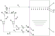
Fig. 1 is a schematic structural diagram of an embodiment of the present invention.
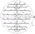
Fig. 2 is a schematic diagram of a planar arrangement structure of a disturbance distribution pipe network in the embodiment of the present invention.
Description of reference numerals:
a desulfurizing tower concentration section 1;
1# sleeve 21; 2# sleeve 22;
1# inlet electric on-off valve 31; 2# inlet electric on-off valve 32;
1# basket strainer 41; the # 2 basket filter 42;
1# inlet blow-off valve 51; 2# inlet blow-off valve 52;
no. 1 hydraulic stirring pump 61; 2# hydraulic mixer pump 62;
outlet 1 flush water valve 71; outlet 2 flush water valve 72;
1# outlet electric on-off valve 81; 2# outlet electric on-off valve 82;
pump inlet line # 1 131; 1# pump outlet conduit 132;
pump # 2 inlet line 141; # 2 pump outlet conduit 142;
a pressure transmitter 9; a connecting pipe 10;
disturbing the distribution pipe network 11; a disturbance distribution main pipe 111; disturbance distribution horizontal leg 112; a disturbance distribution vertical branch 113; a support beam 114;
the nozzle 12 is perturbed.
Detailed Description
The present invention will be described in further detail below by way of examples with reference to the accompanying drawings, which are illustrative of the present invention and are not to be construed as limiting the present invention.
Examples are given.
See fig. 1-2.
The embodiment discloses an ammonia flue gas desulfurization hydraulic stirring system which comprises a sleeve, a hydraulic stirring and conveying device, a connecting pipeline 10, a pressure transmitter 9, a disturbance distribution pipe network 11 and a disturbance nozzle 12; the sleeve, the hydraulic stirring and conveying device, the connecting pipeline 10 and the disturbance distribution pipe network 11 are sequentially connected; the pressure transmitter 9 is mounted on the connecting pipe 10. The connecting pipe 10 is made of FRP, and the pressure grade is PN 10.
In this embodiment, the pressure transmitter 9 is diaphragm type with a range of 0-0.6Mpa, intelligent two-wire system, diaphragm material: HC-276.
In the embodiment, the sleeve is made of FRP, one end of the sleeve is connected with the bottom of the concentration section 1 of the desulfurizing tower, specifically, the concentration section 1 of the desulfurizing tower is made of carbon steel and is subjected to glass flake anticorrosion treatment for storing ammonium sulfate slurry, and crystallization of ammonium sulfate is carried out in the concentration section 1 of the desulfurizing tower; the concentrated section of desulfurizing tower 1 bottom is provided with reserves the mouth of pipe, and the sleeve pipe passes through flange joint with reserving the mouth of pipe, and sheathed tube one end is from the concentrated section of desulfurizing tower 1 bottom of injecting 1 inside the concentrated section of desulfurizing tower for extract the ammonium sulfate thick liquid of bottom. And the distance from the end part of the sleeve positioned in the concentrating section 1 of the desulfurizing tower to the bottom plate of the desulfurizing tower is 400 mm.
In the embodiment, the disturbance distribution pipe network 11 is arranged inside the concentration section 1 of the desulfurizing tower; a plurality of disturbance nozzles 12 are arranged and are arranged on the disturbance distribution pipe network 11 in a mode that nozzles face downwards; the hydraulic stirring and conveying device conveys the slurry at the bottom of the concentration section 1 of the desulfurizing tower upwards to a disturbance distribution pipe network 11 through a sleeve and a connecting pipeline 10 and then sprays the slurry downwards through a disturbance nozzle 12.
Specifically, the disturbance distribution piping network 11 includes disturbance distribution main pipes 111, disturbance distribution horizontal branch pipes 112, disturbance distribution vertical branch pipes 113, and support beams 114. The supporting beam 114 is arranged at the middle upper part inside the concentration section 1 of the desulfurizing tower and is fixedly connected with the inner wall of the desulfurizing tower. One disturbance distribution main pipe 111 is arranged, and a plurality of disturbance distribution horizontal branch pipes 112 and a plurality of disturbance distribution vertical branch pipes 113 are arranged; the main disturbance distribution pipe 111 and all the horizontal disturbance distribution branch pipes 112 are horizontally arranged on the support beam 114, and rubber pads are arranged at the positions where the main disturbance distribution pipe 111 and the horizontal disturbance distribution branch pipes 112 are in contact with the support beam 114.
In this embodiment, one end of the disturbance distribution main pipe 111 penetrates through the desulfurization tower and is connected with the connecting pipeline 10; all the disturbance distribution horizontal branch pipes 112 are connected with the disturbance distribution main pipe 111; all the disturbance distribution horizontal branch pipes 112 are uniformly distributed in the cross section of the whole concentration section 1 of the desulfurization tower. The disturbance distribution vertical branch pipe 113 is vertically installed, one end of the disturbance distribution vertical branch pipe is connected with the disturbance distribution horizontal branch pipe 112, and the other end is installed with the disturbance nozzle 12.
In this embodiment, the central elevation of the disturbance distribution main pipe 111 is +1850mm, the wall thicknesses of the disturbance distribution main pipe 111, the disturbance distribution horizontal branch pipes 112 and the disturbance distribution vertical branch pipes 113 are not less than 10mm, the resistance to pH 2-10, the temperature of 100 ℃, the pressure resistance of 1.0MPa is required, the inner and outer walls are both required to be wear-resistant, the inner layer of the wear-resistant layer is not less than 3mm, the outer wall is not less than 4mm, and the support beam 114 is made of carbon steel and is subjected to glass flake anticorrosion treatment.
In this embodiment, the main disturbance distribution pipe 111 is a gradual reducing pipe, and the pipe diameter of the pipe gradually decreases from the middle to the two ends. Similarly, the disturbance distribution horizontal branch pipe 112 is also designed as a gradual reducing pipe, and the gradual reducing disturbance distribution main pipe 111 and the disturbance distribution horizontal branch pipe 112 can uniformly distribute the ammonium sulfate slurry to each disturbance distribution vertical branch pipe 113.
In this embodiment, disturbance nozzle 12 is used for atomizing into tiny liquid drop with the ammonium sulfate thick liquid, and the liquid drop after the atomizing sprays from the nozzle with certain pressure and cover surface and down, and the ammonium sulfate thick liquid of 1 bottom of the concentrated section of desulfurizing tower receives to strike the back and floats, so circulation, has both avoided the deposit of ammonium sulfate thick liquid, has improved the degree of consistency of concentrated section thick liquid again, realizes the effect of the concentrated section of desulfurizing tower 1 thick liquid hydraulic stirring. The covering surface of each nozzle is circular, the diameter is about 3m, the sprayed liquid drops can cover the whole bottom plate of the desulfurization tower, and the height between the outlet of each nozzle and the bottom plate of the desulfurization tower is 1000 mm.
In this embodiment, the hydraulic stirring and conveying device includes a hydraulic stirring pump, a pump inlet pipeline, a pump outlet pipeline, an inlet electric switch valve, a basket filter, an inlet blow-down valve, an outlet flushing water valve, and an outlet electric switch valve. The inlet end of the hydraulic stirring pump is connected with one end of a pump inlet pipeline, and the other end of the pump inlet pipeline is connected with the sleeve; the inlet electric switch valve, the basket filter and the inlet emptying valve are sequentially arranged on a pump inlet pipeline according to the liquid conveying direction; the outlet end of the hydraulic stirring pump is connected with one end of an outlet pipeline of the pump, and the other end of the outlet pipeline of the pump is connected with a connecting pipeline 10; the outlet flushing water valve and the outlet electric switch valve are sequentially arranged on the outlet pipeline of the pump according to the liquid conveying direction.
In this embodiment, the inlet electrical on-off valve is used to control the ammonium sulfate slurry to enter the hydraulic mixer pump. The basket filter is used for filtering impurities in the ammonium sulfate slurry and protecting an impeller and a disturbance nozzle of the hydraulic stirring pump. The inlet emptying valve is used for emptying the ammonium sulfate slurry in the system. The hydraulic stirring pump is used for pumping the ammonium sulfate slurry at the bottom of the concentration section 1 of the desulfurizing tower to a disturbance distribution pipe network at a certain pressure. When the hydraulic stirring pump stops operating, the outlet flushing water valve is used for flushing the ammonium sulfate slurry in the pipeline, and the outlet flushing water valve is communicated with the process water pipeline of the desulfurization system. The outlet electric switch valve is used for controlling the output of the ammonium sulfate slurry. The pressure transmitter is used for measuring the pressure at the outlet of the hydraulic stirring pump.
In the embodiment, the hydraulic stirring pump is an all-metal horizontal centrifugal pump, the pump head of the pump is 23m, the material of the flow passage component of the pump is not lower than 2507 duplex stainless steel, and the pump can bear pH =2 and chloride ions 60000 ppm. The central elevation of the pump inlet pipeline is 1100mm, and the bottom plate of the desulfurizing tower needs to be treated by an FRP reinforcing layer and a medium-temperature wear-resistant layer.
In this embodiment, the inlet electric switch valve, the inlet blow-down valve, the outlet flushing water valve and the outlet electric switch valve are all flange-type butterfly valves. The valve body is a WCB liner F46, the valve plate is 2507, the valve seat is F46, and the valve rod is 2Cr 13. The basket filter is a straight-through type, the body is made of glass fiber reinforced plastics, the filter screen is made of 2205 materials, the internal filter cylinder can be freely drawn out, the filtering area of the filter screen is required to be more than 3 times of the through diameter of the pipeline, 4-5 times is recommended, and the opening specification is not less than 12 mm. And an inlet emptying valve is connected into a trench and collected to a pit of a desulfurization area for recycling.
In this embodiment, in order to prevent that hydraulic stirring conveyor from breaking down and influencing the normal work of desulfurizing tower, specially set up hydraulic stirring conveyor two sets in parallel, one is used and is equipped with, correspondingly, the sleeve pipe also sets up two: the number 1 casing pipe 21 and the number 2 casing pipe 22, one casing pipe corresponds to a set of hydraulic stirring and conveying device.
Referring to fig. 1, the first set of hydraulic stirring and conveying device comprises a # 1 inlet electric switch valve 31, a # 1 basket filter 41, a # 1 inlet emptying valve 51, a # 1 hydraulic stirring pump 61, a # 1 outlet flushing water valve 71, a # 1 outlet electric switch valve 81, a # 1 pump inlet pipeline 131 and a # 1 pump outlet pipeline 132.
Referring to fig. 1, the second set of hydraulic mixing and delivery apparatus includes the # 2 inlet electric on-off valve 32, the # 2 basket filter 42, the # 2 inlet blow-down valve 52, the # 2 hydraulic mixing pump 62, the # 2 outlet flush water valve 72, the # 2 outlet electric on-off valve 82, the # 2 pump inlet line 141, and the # 2 pump outlet line 142.
Two pump outlet pipelines in the two sets of hydraulic stirring conveying devices are connected with the connecting pipeline 10 after the conveying tail ends are converged.
The implementation case is as follows: taking a hydraulic stirring system of a certain ammonia flue gas desulfurization project as an example, the pressure grade of the system is PN10, and the diameter of the concentration section 1 of the desulfurizing tower is 15 m; the specifications of the sleeve, the inlet electric switch valve and the basket filter are DN 700; the specification of the inlet emptying valve is DN 50; carrying out dry bottom-up pressure equalization on the hydraulic stirring pump, wherein the flow rate Q =1700 m/H and the lift H =23 m; the specification of the outlet flushing water valve is DN 50; the specification of the outlet electric switch valve is DN 600; the specification of the pressure transmitter is DN 50; the specification of the connecting pipeline 10 is DN700/DN600/DN 50; the pipe diameter of the main disturbance distribution pipe 111 is changed from DN600 to DN350 and then to DN200, the diameter of the horizontal disturbance distribution branch pipe 112 is changed from DN150 to DN125 and then to DN100, and the specification of the vertical disturbance distribution branch pipe 113 is DN 100; the perturbation nozzle 12 is of the specification DN100 and is 36 in number.
Taking the starting of the No. 1 hydraulic stirring pump 61 as an example, the operation method of the hydraulic stirring system for ammonia flue gas desulfurization comprises the following steps:
the method comprises the following steps: after the ammonia flue gas desulfurization hydraulic stirring system is installed, the center elevation of a pump inlet pipeline is +1100mm, the distance between a sleeve and a bottom plate of a desulfurization tower is 400mm, the center elevation of a disturbance distribution main pipe is +1850mm, and the height between a nozzle outlet and the bottom plate of the desulfurization tower is 1000 mm;
step two: checking the states of the valve and the pump, wherein the inlet electric switch valve, the inlet emptying valve, the outlet flushing water valve and the outlet electric switch valve are in a closed state, and the hydraulic stirring pump is in a stop state;
step three: opening the 1# inlet electric switch valve 31 and the 1# outlet electric switch valve 81;
step four: when the liquid level of the 1 liquid level of the concentration section of the desulfurizing tower is greater than 1.5m, a 1# hydraulic stirring pump 61 is started, ammonium sulfate slurry at the bottom of the 1 concentration section of the desulfurizing tower is continuously and sequentially extracted through a 1# sleeve 21, filtered through a 1# basket filter 41 and conveyed to a disturbance distribution pipe network 11 through a connecting pipeline 10, and then passes through a disturbance distribution main pipe 111, a disturbance distribution horizontal branch pipe 112 and a disturbance distribution vertical branch pipe 113 which are gradually reduced, the ammonium sulfate slurry is uniformly distributed to each disturbance nozzle 12, the reading of a pressure transmitter 9 is about 0.23MPa after stable operation, atomized liquid drops are sprayed from the nozzles with a certain coverage surface and pressure, the ammonium sulfate slurry at the bottom of the concentration section of the desulfurizing tower floats after being impacted, and is circularly stirred;
step five: after the use is finished, stopping the No. 1 hydraulic stirring pump 61, closing the No. 1 inlet electric switch valve 31, opening the No. 1 inlet emptying valve 51, and emptying the ammonium sulfate slurry in the No. 1 hydraulic stirring pump 61 and the connecting pipeline 10; closing the 1# inlet emptying valve 51, opening the 1# outlet flushing water valve 71 to flush the 1# pump outlet pipeline 132, and closing the 1# outlet flushing water valve 71 after 5 minutes; the 1# inlet vent valve 51 is opened again, the 1# hydraulic mixer pump 61 and the connecting pipe 10 are vented, and finally the 1# outlet electric switch valve 81 and the 1# inlet vent valve 51 are closed.
And if the first set of hydraulic stirring and conveying device breaks down and needs maintenance, starting the second set of hydraulic stirring and conveying device.
In addition, it should be noted that the specific embodiments described in the present specification may be different in the components, the shapes of the components, the names of the components, and the like, and the above description is only an illustration of the structure of the present invention. All equivalent or simple changes in the structure, characteristics and principles of the invention are included in the protection scope of the patent. Various modifications, additions and substitutions for the specific embodiments described may be made by those skilled in the art without departing from the scope of the invention as defined in the accompanying claims.
Claims (8)
1. The utility model provides an ammonia process flue gas desulfurization hydraulic stirring system which characterized in that: comprises a sleeve, a hydraulic stirring and conveying device, a connecting pipeline (10), a pressure transmitter (9), a disturbance distribution pipe network (11) and a disturbance nozzle (12); the sleeve, the hydraulic stirring and conveying device, the connecting pipeline (10) and the disturbance distribution pipe network (11) are sequentially connected; the pressure transmitter (9) is arranged on the connecting pipeline (10), one end of the sleeve is connected with the bottom of the concentration section (1) of the desulfurizing tower, and the disturbance distribution pipe network (11) is arranged inside the concentration section (1) of the desulfurizing tower; the disturbance nozzles (12) are arranged in plurality and are arranged on the disturbance distribution pipe network (11) in a mode that the nozzles face downwards; the hydraulic stirring and conveying device conveys the slurry at the bottom of the concentration section (1) of the desulfurizing tower upwards to a disturbance distribution pipe network (11) through a sleeve and a connecting pipeline (10) and then downwards sprays the slurry through a disturbance nozzle (12); the hydraulic stirring and conveying device comprises a hydraulic stirring pump, a pump inlet pipeline, a pump outlet pipeline, an inlet electric switch valve, a basket filter, an inlet emptying valve, an outlet flushing water valve and an outlet electric switch valve; the inlet end of the hydraulic stirring pump is connected with one end of a pump inlet pipeline, and the other end of the pump inlet pipeline is connected with the sleeve; the inlet electric switch valve, the basket filter and the inlet emptying valve are sequentially arranged on a pump inlet pipeline according to the liquid conveying direction; the outlet end of the hydraulic stirring pump is connected with one end of an outlet pipeline of the pump, and the other end of the outlet pipeline of the pump is connected with a connecting pipeline (10); the outlet flushing water valve and the outlet electric switch valve are sequentially arranged on an outlet pipeline of the pump according to the liquid conveying direction; the disturbance distribution pipe network (11) comprises a disturbance distribution main pipe (111), a disturbance distribution horizontal branch pipe (112), a disturbance distribution vertical branch pipe (113) and a support beam (114); the supporting beam (114) is arranged at the middle upper part inside the concentration section (1) of the desulfurizing tower and is fixedly connected with the inner wall of the desulfurizing tower; one disturbance distribution main pipe (111) is arranged, and a plurality of disturbance distribution horizontal branch pipes (112) and a plurality of disturbance distribution vertical branch pipes (113) are arranged; the main disturbance distribution pipe (111) and all the horizontal disturbance distribution branch pipes (112) are horizontally arranged on the support beam (114), and rubber pads are arranged at the positions where the main disturbance distribution pipe (111) and the horizontal disturbance distribution branch pipes (112) are in contact with the support beam (114); one end of the disturbance distribution main pipe (111) penetrates out of the desulfurizing tower and then is connected with the connecting pipeline (10); all the disturbance distribution horizontal branch pipes (112) are connected with the disturbance distribution main pipe (111); the disturbance distribution vertical branch pipe (113) is vertically installed, one end of the disturbance distribution vertical branch pipe is connected with the disturbance distribution horizontal branch pipe (112), and the other end of the disturbance distribution vertical branch pipe is provided with a disturbance nozzle (12).
2. The ammonia flue gas desulfurization hydraulic mixing system of claim 1, characterized in that: the hydraulic stirring and conveying devices are arranged in parallel, one is used, the other is standby, and two pump outlet pipelines in the two hydraulic stirring and conveying devices are connected with the connecting pipeline (10) after the conveying tail ends are converged.
3. The ammonia flue gas desulfurization hydraulic mixing system of claim 1, characterized in that: the disturbance distribution main pipe (111) is a gradual reducing pipe, and the pipe diameter of the disturbance distribution main pipe is gradually reduced from the middle to the two ends; all the disturbance distribution horizontal branch pipes (112) are uniformly distributed in the cross section of the whole desulfurizing tower concentration section (1).
4. The ammonia flue gas desulfurization hydraulic mixing system of claim 1, characterized in that: one end of the sleeve is inserted into the concentrating section of the desulfurizing tower from the bottom of the concentrating section (1) of the desulfurizing tower, and the distance between the end part of the sleeve positioned in the concentrating section of the desulfurizing tower and the bottom plate of the desulfurizing tower is 400 mm; the sleeve is made of FRP.
5. The ammonia flue gas desulfurization hydraulic mixing system of claim 1, characterized in that: and the inlet electric switch valve, the inlet emptying valve, the outlet flushing water valve and the outlet electric switch valve are all flange type butterfly valves.
6. The ammonia flue gas desulfurization hydraulic mixing system of claim 1, characterized in that: the inlet blow-down valve is connected to the trench.
7. The ammonia flue gas desulfurization hydraulic mixing system of claim 1, characterized in that: the height of the outlet of the disturbance nozzle (12) from the bottom plate of the desulfurizing tower is 1000 mm.
8. An operation method of the ammonia flue gas desulfurization hydraulic stirring system according to any one of claims 1 to 7, characterized in that: the method comprises the following steps:
the method comprises the following steps: after the ammonia flue gas desulfurization hydraulic stirring system is installed, the center of a pump inlet pipeline is subjected to elevation according to the specific size of a desulfurization tower, and the center elevation of a disturbance distribution main pipe (111) is subjected to elevation, so that the distance between a sleeve and the bottom plate of the desulfurization tower is 400mm, and the distance between the outlet of a disturbance nozzle (12) and the bottom plate of the desulfurization tower is 1000 mm;
step two: check valve and pump status: the inlet electric switch valve, the inlet emptying valve, the outlet flushing water valve and the outlet electric switch valve are in a closed state, and the hydraulic stirring pump is in a stop state;
step three: opening an inlet electric switch valve and an outlet electric switch valve;
step four: when the liquid level of the concentration section of the desulfurizing tower is more than 1.5m, a hydraulic stirring pump is started, ammonium sulfate slurry at the bottom of the concentration section of the desulfurizing tower is continuously and sequentially extracted by a sleeve, filtered by a basket filter and conveyed to a disturbance distribution pipe network (11) by a connecting pipeline (10), and then passes through a disturbance distribution main pipe (111), a disturbance distribution horizontal branch pipe (112) and a disturbance distribution vertical branch pipe (113) which are gradually reduced, the ammonium sulfate slurry is uniformly distributed to each disturbance nozzle (12), atomized liquid drops are sprayed from the nozzles at a certain coverage surface and pressure, the ammonium sulfate slurry at the bottom of the concentration section of the desulfurizing tower floats after being impacted, and the circulation stirring is carried out;
step five: after the use is finished, stopping the hydraulic stirring pump, closing the inlet electric switch valve, opening the inlet emptying valve, and emptying the ammonium sulfate slurry in the hydraulic stirring pump and the connecting pipeline (10); closing the inlet blow-down valve, opening the outlet flushing water valve to flush the outlet pipeline of the pump, and closing the outlet flushing water valve after flushing for a period of time; opening the inlet vent valve again, venting the hydraulic stirring pump and the connecting pipeline (10), and finally closing the outlet electric switch valve and the inlet vent valve; and if the first set of hydraulic stirring and conveying device breaks down and needs maintenance, starting the second set of hydraulic stirring and conveying device.
Priority Applications (1)
| Application Number | Priority Date | Filing Date | Title |
|---|---|---|---|
| CN202010246775.2A CN111282464A (en) | 2020-03-31 | 2020-03-31 | Ammonia flue gas desulfurization hydraulic stirring system and operation method thereof |
Applications Claiming Priority (1)
| Application Number | Priority Date | Filing Date | Title |
|---|---|---|---|
| CN202010246775.2A CN111282464A (en) | 2020-03-31 | 2020-03-31 | Ammonia flue gas desulfurization hydraulic stirring system and operation method thereof |
Publications (1)
| Publication Number | Publication Date |
|---|---|
| CN111282464A true CN111282464A (en) | 2020-06-16 |
Family
ID=71027308
Family Applications (1)
| Application Number | Title | Priority Date | Filing Date |
|---|---|---|---|
| CN202010246775.2A Pending CN111282464A (en) | 2020-03-31 | 2020-03-31 | Ammonia flue gas desulfurization hydraulic stirring system and operation method thereof |
Country Status (1)
| Country | Link |
|---|---|
| CN (1) | CN111282464A (en) |
Citations (9)
| Publication number | Priority date | Publication date | Assignee | Title |
|---|---|---|---|---|
| US20130195728A1 (en) * | 2010-05-14 | 2013-08-01 | Houjie Sun | Wet flue gas desulfurization absorption tower for for power plant |
| CN203379794U (en) * | 2013-05-22 | 2014-01-08 | 高翀 | Suspension disturbance device for flue gas desulfurization by ammonia process |
| US20140050651A1 (en) * | 2011-02-16 | 2014-02-20 | Jingyao Xu | System and process for trapping sulfur dioxide and carbon dioxide by ammonia absorption at atmospheric pressure |
| CN204543976U (en) * | 2015-03-25 | 2015-08-12 | 上海海涵环保科技有限公司 | A kind of disturbance device for desulfurizing tower |
| CN206199004U (en) * | 2016-11-17 | 2017-05-31 | 大唐环境产业集团股份有限公司 | A kind of novel hydraulic energetic disturbance system |
| US20190001257A1 (en) * | 2017-07-03 | 2019-01-03 | Marsulex Environmental Technologies Corporation | Wet flue gas desulfurization process and apparatus |
| CN208389778U (en) * | 2018-04-03 | 2019-01-18 | 中国联合工程有限公司 | Spray proposes the wear-resisting composite structure of effect |
| CN208493856U (en) * | 2018-02-08 | 2019-02-15 | 江苏科行环保股份有限公司 | A kind of agitating device of the ammonium sulfate slurries suitable for ammonia desulfurizing process |
| CN212369950U (en) * | 2020-03-31 | 2021-01-19 | 中国联合工程有限公司 | Hydraulic stirring system for ammonia flue gas desulfurization |
-
2020
- 2020-03-31 CN CN202010246775.2A patent/CN111282464A/en active Pending
Patent Citations (9)
| Publication number | Priority date | Publication date | Assignee | Title |
|---|---|---|---|---|
| US20130195728A1 (en) * | 2010-05-14 | 2013-08-01 | Houjie Sun | Wet flue gas desulfurization absorption tower for for power plant |
| US20140050651A1 (en) * | 2011-02-16 | 2014-02-20 | Jingyao Xu | System and process for trapping sulfur dioxide and carbon dioxide by ammonia absorption at atmospheric pressure |
| CN203379794U (en) * | 2013-05-22 | 2014-01-08 | 高翀 | Suspension disturbance device for flue gas desulfurization by ammonia process |
| CN204543976U (en) * | 2015-03-25 | 2015-08-12 | 上海海涵环保科技有限公司 | A kind of disturbance device for desulfurizing tower |
| CN206199004U (en) * | 2016-11-17 | 2017-05-31 | 大唐环境产业集团股份有限公司 | A kind of novel hydraulic energetic disturbance system |
| US20190001257A1 (en) * | 2017-07-03 | 2019-01-03 | Marsulex Environmental Technologies Corporation | Wet flue gas desulfurization process and apparatus |
| CN208493856U (en) * | 2018-02-08 | 2019-02-15 | 江苏科行环保股份有限公司 | A kind of agitating device of the ammonium sulfate slurries suitable for ammonia desulfurizing process |
| CN208389778U (en) * | 2018-04-03 | 2019-01-18 | 中国联合工程有限公司 | Spray proposes the wear-resisting composite structure of effect |
| CN212369950U (en) * | 2020-03-31 | 2021-01-19 | 中国联合工程有限公司 | Hydraulic stirring system for ammonia flue gas desulfurization |
Similar Documents
| Publication | Publication Date | Title |
|---|---|---|
| CN110606552A (en) | Novel sewage treatment rotating biological disk reactor contact reaction tank desilting system | |
| CN101597529B (en) | Methane bio-desulfurization device | |
| CN212369950U (en) | Hydraulic stirring system for ammonia flue gas desulfurization | |
| CN106006944A (en) | Ship-mounted black odoriferous water treatment device | |
| CN204746080U (en) | A spray drying desulphurization unit for cement plant | |
| CN219540005U (en) | Calcium desulfurization tower cauldron thick liquid agitating unit | |
| CN111282464A (en) | Ammonia flue gas desulfurization hydraulic stirring system and operation method thereof | |
| CN217449593U (en) | Novel desulfurization slurry disturbance system | |
| CN2923004Y (en) | Smoke wet-type desulfurizing square absorbing tower | |
| CN207153194U (en) | A kind of hydraulic cyclone and sewage disposal device | |
| CN109279589A (en) | A kind of activated carbon of phosphoric acid method workshop high efficiente callback phosphoric acid plant | |
| CN215388705U (en) | Novel desulfurization liquid-holding layer slurry supply system | |
| CN212974731U (en) | Hydraulic stirring disturbance device for bottom circulation pool of wet desulphurization tower | |
| CN205635174U (en) | Full -automatic water purifier | |
| CN208726946U (en) | Coal slime water purification installation | |
| CN210303187U (en) | System for utilize self priming pump to carry out moisture to desulfurization gypsum thick liquid and collect | |
| CN100542666C (en) | A kind of solid-liquid reaction tanks and application thereof with gas separation and collecting function | |
| CN211620060U (en) | Novel sewage treatment rotating biological disk reactor contact reaction tank desilting system | |
| CN206924617U (en) | A kind of double slurry pool circulating desulfurization devices | |
| CN208104027U (en) | UASB anti-clogging hydraulic jet water distribution system | |
| CN208260519U (en) | A kind of sludge hot hydrolysis process Flash Gas Compression Skid System | |
| CN207619126U (en) | A kind of preaeration jet-flow aeration system | |
| CN100450588C (en) | Square absorption tower for wet method desulfurization of flue gas | |
| CN204395920U (en) | A kind of oxidation tank device | |
| CN220149395U (en) | Underground construction wastewater treatment and calcium carbonate recovery multiplexing device |
Legal Events
| Date | Code | Title | Description |
|---|---|---|---|
| PB01 | Publication | ||
| PB01 | Publication | ||
| SE01 | Entry into force of request for substantive examination | ||
| SE01 | Entry into force of request for substantive examination |