CN111238197A - Combined drying machine - Google Patents
Combined drying machine Download PDFInfo
- Publication number
- CN111238197A CN111238197A CN202010200122.0A CN202010200122A CN111238197A CN 111238197 A CN111238197 A CN 111238197A CN 202010200122 A CN202010200122 A CN 202010200122A CN 111238197 A CN111238197 A CN 111238197A
- Authority
- CN
- China
- Prior art keywords
- groups
- rotating frame
- heat pump
- rotating
- pump unit
- Prior art date
- Legal status (The legal status is an assumption and is not a legal conclusion. Google has not performed a legal analysis and makes no representation as to the accuracy of the status listed.)
- Pending
Links
- 238000001035 drying Methods 0.000 title claims abstract description 76
- 210000001503 joint Anatomy 0.000 claims description 9
- 238000010438 heat treatment Methods 0.000 claims description 7
- 238000009413 insulation Methods 0.000 claims description 7
- 238000005485 electric heating Methods 0.000 claims description 6
- 229910000831 Steel Inorganic materials 0.000 claims description 3
- 239000010959 steel Substances 0.000 claims description 3
- 238000007791 dehumidification Methods 0.000 abstract description 3
- 241001122767 Theaceae Species 0.000 description 9
- 230000004048 modification Effects 0.000 description 2
- 238000012986 modification Methods 0.000 description 2
- 230000009286 beneficial effect Effects 0.000 description 1
- 230000007547 defect Effects 0.000 description 1
- 238000010981 drying operation Methods 0.000 description 1
- 230000000694 effects Effects 0.000 description 1
- 239000006260 foam Substances 0.000 description 1
- 230000002093 peripheral effect Effects 0.000 description 1
- 238000002360 preparation method Methods 0.000 description 1
- 230000001131 transforming effect Effects 0.000 description 1
Images


Classifications
-
- F—MECHANICAL ENGINEERING; LIGHTING; HEATING; WEAPONS; BLASTING
- F26—DRYING
- F26B—DRYING SOLID MATERIALS OR OBJECTS BY REMOVING LIQUID THEREFROM
- F26B11/00—Machines or apparatus for drying solid materials or objects with movement which is non-progressive
- F26B11/18—Machines or apparatus for drying solid materials or objects with movement which is non-progressive on or in moving dishes, trays, pans, or other mainly-open receptacles
-
- A—HUMAN NECESSITIES
- A23—FOODS OR FOODSTUFFS; TREATMENT THEREOF, NOT COVERED BY OTHER CLASSES
- A23F—COFFEE; TEA; THEIR SUBSTITUTES; MANUFACTURE, PREPARATION, OR INFUSION THEREOF
- A23F3/00—Tea; Tea substitutes; Preparations thereof
- A23F3/06—Treating tea before extraction; Preparations produced thereby
-
- F—MECHANICAL ENGINEERING; LIGHTING; HEATING; WEAPONS; BLASTING
- F26—DRYING
- F26B—DRYING SOLID MATERIALS OR OBJECTS BY REMOVING LIQUID THEREFROM
- F26B21/00—Arrangements or duct systems, e.g. in combination with pallet boxes, for supplying and controlling air or gases for drying solid materials or objects
- F26B21/001—Drying-air generating units, e.g. movable, independent of drying enclosure
- F26B21/002—Drying-air generating units, e.g. movable, independent of drying enclosure heating the drying air indirectly, i.e. using a heat exchanger
-
- F—MECHANICAL ENGINEERING; LIGHTING; HEATING; WEAPONS; BLASTING
- F26—DRYING
- F26B—DRYING SOLID MATERIALS OR OBJECTS BY REMOVING LIQUID THEREFROM
- F26B21/00—Arrangements or duct systems, e.g. in combination with pallet boxes, for supplying and controlling air or gases for drying solid materials or objects
- F26B21/06—Controlling, e.g. regulating, parameters of gas supply
- F26B21/08—Humidity
-
- F—MECHANICAL ENGINEERING; LIGHTING; HEATING; WEAPONS; BLASTING
- F26—DRYING
- F26B—DRYING SOLID MATERIALS OR OBJECTS BY REMOVING LIQUID THEREFROM
- F26B25/00—Details of general application not covered by group F26B21/00 or F26B23/00
-
- F—MECHANICAL ENGINEERING; LIGHTING; HEATING; WEAPONS; BLASTING
- F26—DRYING
- F26B—DRYING SOLID MATERIALS OR OBJECTS BY REMOVING LIQUID THEREFROM
- F26B2200/00—Drying processes and machines for solid materials characterised by the specific requirements of the drying good
- F26B2200/20—Teas, i.e. drying, conditioning, withering of tea leaves
Abstract
The invention discloses a combined dryer, which comprises a heat pump unit and a drying chamber, wherein the drying chamber is provided with an air inlet and an air return inlet, the air inlet is communicated with an air outlet of the heat pump unit, the drying chamber is a combined box body, and more than two rotating frames are arranged in the drying chamber and used for placing objects to be dried. The combined dryer can be assembled into two groups of rotary frame dryers, or four groups of rotary frame dryers, or six groups of rotary frame dryers according to the use requirements, and has the advantages of reasonable structure, dehumidification drying, flexible assembly and the like.
Description
Technical Field
The invention discloses a combined dryer, belonging to the technical field of drying equipment according to the classification of International Patent Classification (IPC).
Background
Chinese document CN109506425A discloses an agricultural product drying device, which includes a drying chamber and a heat pump mechanism, the heat pump mechanism includes a compressor, a condenser, an evaporator and a heat pump controller, the air inlet of the drying chamber is communicated with an air inlet pipe, the condenser is arranged at the air inlet of the drying chamber, the agricultural product drying device also includes a drying mechanism, the drying mechanism includes an inner circulation pipe and an outer circulation pipe, and the air entering the air inlet pipe from the outside is condensed and dried, the drying chamber in the document is fixed space capacity, and cannot be expanded or combined to adapt to different requirements.
Tea needs withering and drying in the preparation process, and current tea drying equipment is inefficient, and the tea bracket is fixed knot structure, and tea is heated inhomogeneously.
Disclosure of Invention
Aiming at the defects of the prior art, the invention provides a combined dryer which can expand a drying chamber and increase a rotating frame in the drying chamber, and has the advantages of reasonable structure, dehumidification and drying and flexible assembly.
In order to achieve the purpose, the invention is realized by the following technical scheme:
a combined dryer comprises a heat pump unit and a drying chamber, wherein the drying chamber is provided with an air inlet and an air return inlet, the air inlet is communicated with an air outlet of the heat pump unit, the drying chamber is a combined box body, and more than two rotating frames are arranged in the drying chamber and used for placing objects to be dried.
Furthermore, the rotating frame is provided with a rotating shaft connected with a driving motor on the top surface of the drying chamber, and the bottom of the rotating frame is provided with a mounting seat through a supporting shaft.
Furthermore, the heat pump unit and the drying chamber are independent units, the heat pump unit and the drying chamber are in butt joint to form a whole dryer, the heat pump unit is an air source heat pump mechanism and comprises a heat pump compressor and a heat exchanger which are connected, and a fan is arranged on the outer side of the heat exchanger.
Further, an electric heating device is arranged between the air outlet of the heat pump unit and the air inlet of the drying chamber for heating and dehumidifying.
Further, the electrical heating device is an electrical furnace wire to heat and remove moisture in the air flow passing through.
Further, the heat pump unit and the bottom of the drying chamber are both provided with rollers, the rotating frame in the drying chamber is multi-layer, and a matched steel screen is placed on each layer.
Further, the drying box is two groups of rotating frame boxes, two groups of rotating frames are arranged in the two groups of rotating frame boxes, the two groups of rotating frame boxes comprise back surfaces, two side surfaces and two opening door surfaces, the back surfaces are in butt joint with the heat pump unit, and air inlets and air return openings are formed in the back surfaces.
Further, the drying box is four groups of rotating frame boxes, four groups of rotating frames are arranged in the four groups of rotating frame boxes and are in a square layout, the four groups of rotating frame boxes comprise back faces butted with the heat pump unit, outer faces opposite to the back faces and double door faces on two sides, air inlets and air return openings are formed in the back faces, and heat insulation laminates are arranged between the two groups of rotating frames adjacent to the back faces to form air inlet and return passages.
Furthermore, the drying box is a six-group rotating frame box body, six groups of rotating frames are arranged in the six groups of rotating frame box bodies, the six groups of rotating frame box bodies comprise back faces butted with the heat pump unit, outer double-opening door faces opposite to the back faces and double-opening door faces on two sides, air inlets and air return openings are formed in the back faces, and heat insulation laminated plates are arranged in the middle positions of the back faces and extend towards the outer double-opening door faces.
The drying box is two groups of rotating frame boxes or four groups of rotating frame boxes or six groups of rotating frame boxes, and the two groups of rotating frame boxes or the four groups of rotating frame boxes or the six groups of rotating frame boxes respectively comprise a double-opening door surface which faces the two groups of rotating frames in the box body.
The combined dryer can be used for drying crops, tea leaves and the like, and has the following beneficial effects:
1. the heat pump unit of the dryer can be matched with different drying chambers to perform drying operation, is of a combined structure, has an extensible function, and can be combined into two groups of rotary frame dryers, four groups of rotary frame dryers or six groups of rotary frame dryers.
2. According to the dryer, the rotating frame in the oven is arranged, so that crops or tea leaves on the rotating frame can be uniformly heated, and especially the requirement on tea leaf drying temperature balance is higher.
3. The heat pump unit is additionally provided with the electric heating device, so that the dehumidification of air flow entering the drying chamber is realized, and the drying effect of crops or tea leaves in the drying chamber is improved.
Drawings
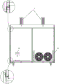
FIG. 1 is a schematic side view of an embodiment of the present invention.
Fig. 2 is a rear view of an embodiment of the present invention.
Fig. 3 is a top view of an embodiment of the present invention.
Fig. 4 is a schematic view of a four-bank rotary rack dryer of the present invention.
Fig. 5 is a schematic view of a six-bank spin stand dryer of the present invention.
Detailed Description
The invention will be further described with reference to the accompanying drawings in which:
example (b): referring to fig. 1 to 5, a combined dryer includes a heat pump unit 1 and a drying chamber 2, the drying chamber 2 has an air inlet and an air return inlet, the air inlet is communicated with an air outlet of the heat pump unit 1, the drying chamber 2 is a combined box, and more than two rotating frames 3 are disposed in the drying chamber 2 for placing objects to be dried. The rotating frame 3 is provided with a rotating shaft connected with a driving motor 4 on the top surface of the drying chamber, the driving motor is a rotating frame rotating motor, and the bottom of the rotating frame is provided with a mounting seat through a supporting shaft. The heat pump unit and the bottom of the drying chamber are both provided with rollers, the rotating frame 3 in the drying chamber is of multiple layers, and a matched steel screen is arranged on each layer. As shown in fig. 1, fig. 3, fig. 4 and fig. 5, the heat pump unit 1 and the drying chamber 2 of the present invention are independent units, the heat pump unit 1 and the drying chamber 2 are butted to form a whole dryer, the heat pump unit 1 is an air source heat pump mechanism and comprises a heat pump compressor 11 and a heat exchanger 12 which are connected, and a fan 13 is arranged outside the heat exchanger 12. An electric heating device is arranged between the air outlet of the heat pump unit 1 and the air inlet of the drying chamber 2 for heating and dehumidifying. The electrical heating means is an electrical heating wire 14 to heat and remove moisture from the passing air stream. The rotating frame of the invention rotates in a reciprocating way in a certain deflection angle opposite to the opening side, the deflection angle is 0-180 degrees, preferably 45-90 degrees, and the purpose is to heat crops or tea leaves of the rotating frame uniformly.
Referring to fig. 3, 4 and 5, the oven chamber of the present invention is two sets of rotating rack chambers or four sets of rotating rack chambers or six sets of rotating rack chambers, and each of the two sets of rotating rack chambers or four sets of rotating rack chambers or six sets of rotating rack chambers includes a double door surface facing two sets of rotating racks in the oven chamber.
As shown in fig. 3, the drying box 2 is two sets of rotating frame boxes, the two sets of rotating frame boxes and the heat pump unit 1 are combined to form two sets of rotating frame dryers 21, two sets of rotating frames 3 are arranged in the two sets of rotating frame boxes, two driving motors are arranged on the boxes, the two sets of rotating frame boxes comprise a back 211, two side faces 212 and two door faces 213, the back 211 and the two door faces are in butt joint with the heat pump unit, foam heat insulation layers 5 are arranged on each face of the boxes, and an air inlet and an air return inlet are arranged on. In two sets of swivel mount drying-machines, two sets of swivel mounts are the parallel arrangement with the heat pump set, and two sets of swivel mount box are parallel butt joint with the heat pump set promptly.
As shown in fig. 4, the drying box 2 is four sets of rotating frame boxes, the four sets of rotating frame boxes are combined with the heat pump unit 1 to form four sets of rotating frame dryers 22, four sets of rotating frames 3 are arranged in the four sets of rotating frame boxes, the four sets of rotating frames 3 are arranged in an open-character layout, the four sets of rotating frame boxes include a back surface 221 butted with the heat pump unit, an outer surface 222 opposite to the back surface, and double door surfaces 223 on two sides, an air inlet and an air return opening are formed in the back surface, and a heat insulation layer plate 220 is arranged between the two sets of rotating frames adjacent to the back. In the four-group rotary frame dryer, the drying box part is formed by transforming two groups of drying boxes (two groups of rotary frame box bodies), the main bodies of the two groups of rotary frame box bodies are vertical to a heat pump unit and are in butt joint, and the peripheral surface and the middle part are correspondingly transformed.
As shown in fig. 5, the drying box 2 is a six-group swivel frame box, the six-group swivel frame box is combined with the heat pump unit 1 to form a six-group swivel frame dryer 23, six groups of swivel frames 3 are arranged in the six-group swivel frame box, the six-group swivel frame box comprises a back 231 butted with the heat pump unit, an outer double-opening door surface 232 opposite to the back, double-opening door surfaces 233 and fixed surfaces 234 on two sides, an air inlet and an air return inlet are arranged on the back, and a heat insulation laminate 230 is arranged in the middle of the back and extends towards the outer double-opening door surface. In the six-group rotary frame dryer, the drying box part is formed by additionally arranging a two-group drying box (two groups of rotary frame boxes) on the outermost surface of four groups of drying boxes (four groups of rotary frame boxes), specifically, the two groups of rotary frame boxes are directly and horizontally arranged outside the four groups of rotary frame boxes, and the adjacent surfaces and the middle parts are correspondingly modified.
The drying box can be two groups of rotating frame boxes or four groups of rotating frame boxes or six groups of rotating frame boxes, and can be quickly combined through a quick combination interface during modification, such as a partial enlarged view in fig. 2 and 3. The dryer can be expanded from two groups to four groups or six groups along with the increase of the drying capacity of a user, the assembly is flexible, and the power of the heat pump unit meets the requirements of being suitable for two groups, four groups or six groups of drying chambers.
When the electric heating device is used, the electric heating device is controlled to be turned on or turned off through the controller 6 according to actual needs. The heat pump unit is started by the controller 6 to work, the air flow enters the drying chamber through the air inlet of the butt joint surface of the drying chamber 2 and the heat pump unit 1, the rotating frame 3 rotates, the air flow dries multiple layers of crops or tea leaves on the rotating frame, and the air flow is added to the heat pump unit through the air return opening to realize circulation.
The present invention is not limited to the above-described embodiments, and alternatives, modifications, equivalents and solutions which are designed to have the same or similar structures as or to be within the spirit and scope of the present invention are also within the scope of the present invention.
Claims (10)
1. A kind of combined dryer, characterized by: the drying box is a combined box body, and more than two rotating frames are arranged in the drying box and used for placing objects to be dried.
2. The combination dryer of claim 1, wherein: the rotating frame is provided with a rotating shaft connected with a driving motor on the top surface of the drying chamber, and the bottom of the rotating frame is provided with a mounting seat through a supporting shaft.
3. The combination dryer of claim 1, wherein: the heat pump unit and the drying chamber are independent units, the heat pump unit and the drying chamber are in butt joint to form a whole dryer, the heat pump unit is an air source heat pump mechanism, the air source heat pump mechanism comprises a heat pump compressor and a heat exchanger which are connected, and a fan is arranged on the outer side of the heat exchanger.
4. The combination dryer of claim 1, wherein: an electric heating device is arranged between the air outlet of the heat pump unit and the air inlet of the drying chamber for heating and dehumidifying.
5. The combination dryer of claim 4, wherein: the electrical heating device is an electrical furnace wire to heat and remove moisture in the air flow passing through.
6. The combination dryer of claim 1, wherein: the heat pump unit and the bottom of the drying chamber are both provided with rollers, the rotating frame in the drying chamber is in multiple layers, and a matched steel screen is arranged on each layer.
7. The combination dryer of one of claims 1 to 6, wherein: the drying box is two groups of rotating frame boxes, two groups of rotating frames are arranged in the two groups of rotating frame boxes, the two groups of rotating frame boxes comprise back surfaces, two side surfaces and two opening door surfaces, which are in butt joint with the heat pump unit, and air inlets and air return openings are formed in the back surfaces.
8. The combination dryer of one of claims 1 to 6, wherein: the drying box is a box body with four groups of rotating frames, the four groups of rotating frames are arranged in the box body with four groups of rotating frames, the four groups of rotating frames are arranged in a square shape, the box body with four groups of rotating frames comprises a back surface which is in butt joint with the heat pump unit, an outer surface which is opposite to the back surface and double door surfaces at two sides, the back surface is provided with an air inlet and an air return opening, and a heat insulation layer plate is arranged between the two groups of rotating frames adjacent to the back.
9. The combination dryer of one of claims 1 to 6, wherein: the drying box is a six-group rotating frame box body, six groups of rotating frames are arranged in the six groups of rotating frame box bodies, the six groups of rotating frame box bodies comprise back faces butted with the heat pump units, outer double-opening door faces opposite to the back faces and double-opening door faces on two sides, air inlets and air return openings are formed in the back faces, and heat insulation laminates are arranged in the middle positions of the back faces and extend towards the outer double-opening door faces.
10. The combination dryer of one of claims 1 to 6, wherein: the drying box is two groups of rotating frame boxes or four groups of rotating frame boxes or six groups of rotating frame boxes, and the two groups of rotating frame boxes or the four groups of rotating frame boxes or the six groups of rotating frame boxes respectively comprise a double-opening door surface which faces the two groups of rotating frames in the box body.
Priority Applications (1)
| Application Number | Priority Date | Filing Date | Title |
|---|---|---|---|
| CN202010200122.0A CN111238197A (en) | 2020-03-20 | 2020-03-20 | Combined drying machine |
Applications Claiming Priority (1)
| Application Number | Priority Date | Filing Date | Title |
|---|---|---|---|
| CN202010200122.0A CN111238197A (en) | 2020-03-20 | 2020-03-20 | Combined drying machine |
Publications (1)
| Publication Number | Publication Date |
|---|---|
| CN111238197A true CN111238197A (en) | 2020-06-05 |
Family
ID=70875629
Family Applications (1)
| Application Number | Title | Priority Date | Filing Date |
|---|---|---|---|
| CN202010200122.0A Pending CN111238197A (en) | 2020-03-20 | 2020-03-20 | Combined drying machine |
Country Status (1)
| Country | Link |
|---|---|
| CN (1) | CN111238197A (en) |
Citations (8)
| Publication number | Priority date | Publication date | Assignee | Title |
|---|---|---|---|---|
| CN201343883Y (en) * | 2008-11-17 | 2009-11-11 | 贵州省烟草科学研究所 | Combined type movable curing barn |
| CN104729261A (en) * | 2015-03-24 | 2015-06-24 | 河北省机电一体化中试基地 | Circulation type energy saving heat pump drying system for drying crops |
| CN205561461U (en) * | 2016-02-03 | 2016-09-07 | 昆明农沃新能源科技有限公司 | Combination heat source formula fruit vegetables drying -machine |
| KR20170054748A (en) * | 2015-11-10 | 2017-05-18 | 주식회사 청록공간 | Versatile vacuum devices |
| CN207066049U (en) * | 2017-06-30 | 2018-03-02 | 湖南中茶茶业有限公司 | A kind of novel energy-conserving tea drier |
| CN208108678U (en) * | 2018-04-20 | 2018-11-16 | 浙江正理生能科技有限公司 | Baking room |
| CN208487920U (en) * | 2018-06-13 | 2019-02-12 | 厦门本草真源生物医药科技有限公司 | A kind of medicinal material drying device |
| CN211854749U (en) * | 2020-03-20 | 2020-11-03 | 驰春机械(厦门)有限公司 | Combined drying machine |
-
2020
- 2020-03-20 CN CN202010200122.0A patent/CN111238197A/en active Pending
Patent Citations (8)
| Publication number | Priority date | Publication date | Assignee | Title |
|---|---|---|---|---|
| CN201343883Y (en) * | 2008-11-17 | 2009-11-11 | 贵州省烟草科学研究所 | Combined type movable curing barn |
| CN104729261A (en) * | 2015-03-24 | 2015-06-24 | 河北省机电一体化中试基地 | Circulation type energy saving heat pump drying system for drying crops |
| KR20170054748A (en) * | 2015-11-10 | 2017-05-18 | 주식회사 청록공간 | Versatile vacuum devices |
| CN205561461U (en) * | 2016-02-03 | 2016-09-07 | 昆明农沃新能源科技有限公司 | Combination heat source formula fruit vegetables drying -machine |
| CN207066049U (en) * | 2017-06-30 | 2018-03-02 | 湖南中茶茶业有限公司 | A kind of novel energy-conserving tea drier |
| CN208108678U (en) * | 2018-04-20 | 2018-11-16 | 浙江正理生能科技有限公司 | Baking room |
| CN208487920U (en) * | 2018-06-13 | 2019-02-12 | 厦门本草真源生物医药科技有限公司 | A kind of medicinal material drying device |
| CN211854749U (en) * | 2020-03-20 | 2020-11-03 | 驰春机械(厦门)有限公司 | Combined drying machine |
Similar Documents
| Publication | Publication Date | Title |
|---|---|---|
| TWI352763B (en) | ||
| KR101630143B1 (en) | Dehumidification device and dehumidification system | |
| AU2017385579B2 (en) | Dual type dryer | |
| CN211854749U (en) | Combined drying machine | |
| CN208478872U (en) | A kind of moisture-proof heat dissipation power distribution cabinet | |
| WO2018006448A1 (en) | Dehumidifier system | |
| CN111238197A (en) | Combined drying machine | |
| WO2013153080A1 (en) | Laundry drying machine | |
| US10401053B2 (en) | Fan bracket for a portable dehumidifier | |
| CN211284887U (en) | Dehydrating unit is used in processing of denim cloth | |
| CN213740191U (en) | Clothes treatment equipment | |
| CN210486298U (en) | Convection pressurization wind formula heat pump dehumidification drying machine | |
| CN211261476U (en) | Continuous drying device of paper gypsum board | |
| CN209007261U (en) | A kind of coating oxidation aloxite paper ventilation type drying unit | |
| CN218511393U (en) | Heat pump dryer | |
| CN206398878U (en) | A kind of dehumidifier with fresh air function | |
| CN215176731U (en) | High-efficient stable ground rice piece face piece desiccator | |
| CN218721902U (en) | Rotary drying and dehumidifying all-in-one machine | |
| CN100513902C (en) | Dehumidifier capable of blowing hot-air to room | |
| CN109595700A (en) | A kind of adjustable angle degree type damping dehumidifier | |
| CN218065177U (en) | Dehumidification module, dehumidification device, bathroom heater | |
| CN113310302A (en) | High-efficient stable ground rice piece face piece desiccator | |
| CN116399098B (en) | Air source heat pump dryer | |
| CN218764276U (en) | Dual-system drying room | |
| CN217303394U (en) | Suspension vibration type multifunctional heat pump drying device |
Legal Events
| Date | Code | Title | Description |
|---|---|---|---|
| PB01 | Publication | ||
| PB01 | Publication | ||
| SE01 | Entry into force of request for substantive examination | ||
| SE01 | Entry into force of request for substantive examination |