CN111237656A - Anti-explosion lighting device convenient to replace and long in service life - Google Patents
Anti-explosion lighting device convenient to replace and long in service life Download PDFInfo
- Publication number
- CN111237656A CN111237656A CN202010097937.0A CN202010097937A CN111237656A CN 111237656 A CN111237656 A CN 111237656A CN 202010097937 A CN202010097937 A CN 202010097937A CN 111237656 A CN111237656 A CN 111237656A
- Authority
- CN
- China
- Prior art keywords
- power supply
- lamp
- tube
- explosion
- fixed
- Prior art date
- Legal status (The legal status is an assumption and is not a legal conclusion. Google has not performed a legal analysis and makes no representation as to the accuracy of the status listed.)
- Withdrawn
Links
Images


Classifications
-
- F—MECHANICAL ENGINEERING; LIGHTING; HEATING; WEAPONS; BLASTING
- F21—LIGHTING
- F21L—LIGHTING DEVICES OR SYSTEMS THEREOF, BEING PORTABLE OR SPECIALLY ADAPTED FOR TRANSPORTATION
- F21L2/00—Systems of electric lighting devices
-
- F—MECHANICAL ENGINEERING; LIGHTING; HEATING; WEAPONS; BLASTING
- F21—LIGHTING
- F21V—FUNCTIONAL FEATURES OR DETAILS OF LIGHTING DEVICES OR SYSTEMS THEREOF; STRUCTURAL COMBINATIONS OF LIGHTING DEVICES WITH OTHER ARTICLES, NOT OTHERWISE PROVIDED FOR
- F21V17/00—Fastening of component parts of lighting devices, e.g. shades, globes, refractors, reflectors, filters, screens, grids or protective cages
- F21V17/10—Fastening of component parts of lighting devices, e.g. shades, globes, refractors, reflectors, filters, screens, grids or protective cages characterised by specific fastening means or way of fastening
- F21V17/12—Fastening of component parts of lighting devices, e.g. shades, globes, refractors, reflectors, filters, screens, grids or protective cages characterised by specific fastening means or way of fastening by screwing
-
- F—MECHANICAL ENGINEERING; LIGHTING; HEATING; WEAPONS; BLASTING
- F21—LIGHTING
- F21V—FUNCTIONAL FEATURES OR DETAILS OF LIGHTING DEVICES OR SYSTEMS THEREOF; STRUCTURAL COMBINATIONS OF LIGHTING DEVICES WITH OTHER ARTICLES, NOT OTHERWISE PROVIDED FOR
- F21V17/00—Fastening of component parts of lighting devices, e.g. shades, globes, refractors, reflectors, filters, screens, grids or protective cages
- F21V17/10—Fastening of component parts of lighting devices, e.g. shades, globes, refractors, reflectors, filters, screens, grids or protective cages characterised by specific fastening means or way of fastening
- F21V17/16—Fastening of component parts of lighting devices, e.g. shades, globes, refractors, reflectors, filters, screens, grids or protective cages characterised by specific fastening means or way of fastening by deformation of parts; Snap action mounting
- F21V17/162—Fastening of component parts of lighting devices, e.g. shades, globes, refractors, reflectors, filters, screens, grids or protective cages characterised by specific fastening means or way of fastening by deformation of parts; Snap action mounting the parts being subjected to traction or compression, e.g. coil springs
-
- F—MECHANICAL ENGINEERING; LIGHTING; HEATING; WEAPONS; BLASTING
- F21—LIGHTING
- F21V—FUNCTIONAL FEATURES OR DETAILS OF LIGHTING DEVICES OR SYSTEMS THEREOF; STRUCTURAL COMBINATIONS OF LIGHTING DEVICES WITH OTHER ARTICLES, NOT OTHERWISE PROVIDED FOR
- F21V19/00—Fastening of light sources or lamp holders
Abstract
The invention relates to an explosion-proof lighting device with long service life and convenient replacement, which comprises a base, a controller, a bracket, a lamp shell and a sealing mechanism, wherein the lighting mechanism comprises a rotating assembly, a round pipe, a power supply assembly and a plurality of lighting assemblies, each lighting assembly comprises a lamp shade, a lamp tube, a temperature sensor and two mounting units, each power supply assembly comprises a power supply, a telescopic unit, a power supply plate and two power supply blocks, the sealing mechanism comprises a replacement port, a sealing plate, a fixing assembly and a connecting assembly, each fixing assembly comprises an insertion pipe, a threaded pipe and a screw rod, the explosion-proof lighting device with long service life and convenient replacement is characterized in that the sealing mechanism is used for conveniently opening the replacement port, the lighting assemblies corresponding to the replacement port are conveniently replaced when equipment is used or idle, thereby providing the utility of the device.
Description
Technical Field
The invention relates to the field of explosion-proof illumination, in particular to an explosion-proof illumination device which is convenient to replace and long in service life.
Background
The explosion-proof lamp is used in dangerous places where combustible gas and dust exist, and can prevent electric arcs, sparks and high temperature possibly generated in the lamp from igniting the combustible gas and dust in the surrounding environment, so that the lamp which meets the explosion-proof requirement is also called as an explosion-proof lamp and an explosion-proof illuminating lamp, and different combustible gas mixture environments have different requirements on the explosion-proof grade and the explosion-proof form of the explosion-proof lamp, specifically refer to GB3836 and IEC 60079.
In order to guarantee the illumination brightness, the inside of the conventional convenient illuminating lamp generally adopts a high-power illuminating lamp, but in this way, the inside of the lamp is heated up too fast easily, the lamp runs at high temperature, the service life of the lamp is very easy to shorten, and moreover, the lamp tube of the conventional explosion-proof illuminating lamp is usually fixedly installed inside the lamp shell and is not easy to detach and replace, so that the practicability of the conventional explosion-proof illuminating device is reduced.
Disclosure of Invention
The technical problem to be solved by the invention is as follows: in order to overcome the defects of the prior art, the anti-explosion lighting device which is convenient to replace and has long service life is provided.
The technical scheme adopted by the invention for solving the technical problems is as follows: an explosion-proof lighting device convenient to replace and long in service life comprises a base, a controller, a support, a lamp shell and a sealing mechanism, wherein the controller is fixed above the base, a PLC is arranged in the controller, the lamp shell is arranged above the base through the support, the sealing mechanism is positioned above the lamp shell, an opening is formed in one side of the lamp shell, a glass sheet is arranged in the opening, and a lighting mechanism is arranged in the lamp shell;
the lighting mechanism comprises a rotating assembly, a round pipe, a power supply assembly and a plurality of lighting assemblies, wherein the rotating assembly and the power supply assembly are both positioned on the inner side of the round pipe, the lighting assemblies are circumferentially and uniformly distributed on the periphery of the round pipe, each lighting assembly comprises a lampshade, a lamp tube, a temperature sensor and two mounting units, the lampshade is fixed on the round pipe, two ends of each lamp tube are respectively connected with the inner walls of two ends of the lampshade through the two mounting units, the temperature sensors are fixed at the bottom in the lampshade, two conductive blocks are arranged at one end, close to the round pipe, of the lampshade, the power supply assembly comprises a power supply, a telescopic unit, a power supply plate and two power supply blocks, the power supply is fixed in the lamp housing, the power supply and the temperature sensors are both electrically connected with the PLC, the power supply plate is connected with the power supply through, the power supply blocks correspond to the conductive blocks one to one;
the sealing mechanism comprises a replacing port, a sealing plate, a fixing component and a connecting component, the replacing port is arranged on the lamp shell, the sealing plate is covered on the replacing port, two ends of the sealing plate are connected with the lamp shell through the connecting component and the fixing component respectively, the fixing component comprises an insertion pipe, a threaded pipe and a screw rod, the insertion pipe is fixed on the sealing plate, the threaded pipe is fixed on the lamp shell, the insertion pipe and the threaded pipe are sleeved on the screw rod, and a thread matched with the screw rod is arranged at the connecting position of the threaded pipe and the screw rod.
As preferred, rotate for the drive pipe, the runner assembly includes first motor, gear, a plurality of dogtooth and two slip units, first motor is fixed in the lamp body, first motor is connected with the PLC electricity, first motor is connected with gear drive, dogtooth circumference evenly distributed is on the inner wall of pipe, gear and dogtooth meshing, the both ends of pipe are respectively through the interior wall connection at the both ends of two slip units and lamp body.
Preferably, in order to realize the stable rotation of pipe, the slip unit includes ring channel and a plurality of slider, slider circumference evenly distributed is on the pipe, the ring channel is fixed on the inner wall of lamp body, slider and ring channel sliding connection.
Preferably, in order to further realize the stable rotation of the circular tube, the annular groove is a dovetail groove.
Preferably, in order to facilitate the disassembly and assembly of the lamp tube, the mounting unit comprises a sliding rod, a convex plate, a conductive tube and a spring, the convex plate is located on the inner side of the lamp bead, the conductive tube is sleeved on the lamp tube and is electrically connected with the conductive block, the conductive tube is connected with the inner wall of the lamp shade through the spring, the spring is in a compression state, one end of the sliding rod is fixedly connected with the conductive tube, and the other end of the sliding rod penetrates through the lamp shade and is fixedly connected with the convex plate.
Preferably, in order to control the power supply board to move, the telescopic unit comprises an air cylinder, a cylinder body of the air cylinder is fixed on a power supply, an air rod of the air cylinder is fixedly connected with the power supply board, and the air cylinder is electrically connected with the PLC.
Preferably, to avoid corrosion of the screw, the screw is coated with an anti-corrosion zinc coating.
Preferably, in order to facilitate rotation of the sealing plate, the connecting assembly includes a central shaft, a connecting rod and two sleeves, the sleeves are fixed to the lamp housing, two ends of the central rod are respectively disposed in the two sleeves, and the central shaft is fixedly connected to the sealing plate through the connecting rod.
As preferred, for the convenience of equipment removal, the four corners department of base is equipped with the removal subassembly, the removal subassembly includes trompil, mount, lifting unit, lifter plate and gyro wheel, the trompil sets up on the base, the shape of mount is the U-shaped, the top at the base is fixed at the both ends of mount, the both ends of lifter plate are established respectively at the both ends of mount, the lifter plate passes through the lifting unit and is connected with the center department of mount, the gyro wheel is fixed in the below of lifter plate, the gyro wheel is located the trompil directly over.
Preferably, in order to control the lifting plate to move, the lifting unit comprises a second motor, a driving rod and a driven rod, the second motor is fixed below the center of the fixing frame and is electrically connected with the PLC, the second motor is in transmission connection with the driving rod, and the driving rod is hinged to the lifting plate through the driven rod.
The anti-explosion lighting device convenient to replace and long in service life has the advantages that the lighting mechanism drives the circular tube to rotate, high-temperature operation time of the lamp tube is shortened, the service life of the lamp tube is prolonged, the replacement opening is conveniently opened through the sealing mechanism, the lighting assembly corresponding to the replacement opening is conveniently replaced when the device is used or is idle, and therefore the practicability of the device is provided.
Drawings
The invention is further illustrated with reference to the following figures and examples.
FIG. 1 is a schematic structural view of a long-life explosion-proof lighting device of the present invention which is easy to replace;
FIG. 2 is a cross-sectional view of the lamp envelope of the long-life explosion-proof lighting unit of the present invention which is easy to replace;
FIG. 3 is a schematic structural view of the lighting mechanism of the explosion-proof lighting device of the present invention, which is easy to replace and has a long service life;
FIG. 4 is a schematic structural view of the moving assembly of the long-life explosion-proof lighting device of the present invention, which is easy to replace;
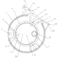
in the figure: 1. the automatic lamp comprises a base, 2 parts of a controller, 3 parts of a bracket, 4 parts of a lamp shell, 5 parts of a glass sheet, 6 parts of a round tube, 7 parts of a lamp shade, 8 parts of a lamp tube, 9 parts of a conductive block, 10 parts of a power supply, 11 parts of a power supply plate, 12 parts of the power supply block, 13 parts of a sealing plate, 14 parts of an insertion tube, 15 parts of a threaded tube, 16 parts of a screw rod, 17 parts of a first motor, 18 parts of a gear, 19 parts of an annular groove, 20 parts of a sliding block, 21 parts of a sliding rod, 22 parts of a convex plate, 23 parts of the conductive tube, 24 parts of a spring, 25 parts of a cylinder, 26 parts of a central shaft, 27 parts of a connecting rod, 28 parts of a sleeve, 29 parts of a fixing frame, 30 parts of a lifting.
Detailed Description
The present invention will now be described in further detail with reference to the accompanying drawings. These drawings are simplified schematic views illustrating only the basic structure of the present invention in a schematic manner, and thus show only the constitution related to the present invention.
As shown in fig. 1, an explosion-proof lighting device with a long service life and convenient to replace comprises a base 1, a controller 2, a support 3, a lamp housing 4 and a sealing mechanism, wherein the controller 2 is fixed above the base 1, a PLC is arranged in the controller 2, the lamp housing 4 is arranged above the base 1 through the support 3, the sealing mechanism is positioned above the lamp housing 4, an opening is formed in one side of the lamp housing 4, a glass sheet 5 is arranged in the opening, and a lighting mechanism is arranged in the lamp housing 4;
a PLC, i.e., a programmable logic controller, which employs a programmable memory for storing therein a program, executing instructions for user-oriented operations such as logic operation, sequence control, timing, counting, and arithmetic operation, and controlling various types of machines or production processes through digital or analog input/output, is essentially a computer dedicated for industrial control, has a hardware structure substantially the same as that of a microcomputer, and is generally used for data processing and instruction reception and output for realizing central control.
In the explosion-proof illuminating lamp, the lamp shell 4 is supported by the support 3, a user can operate the device through the controller 2 to operate, the generated light penetrates through the glass sheet 5 to illuminate the surrounding by using the illuminating mechanism in the lamp shell 4, the lamp shell 4 is conveniently opened through the sealing mechanism, and the lamp tube 8 in the illuminating mechanism is replaced.
As shown in fig. 2-3, the lighting mechanism includes a rotating assembly, a circular tube 6, a power supply assembly and a plurality of lighting assemblies, the rotating assembly and the power supply assembly are both located inside the circular tube 6, the lighting assemblies are circumferentially and uniformly distributed around the circular tube 6, the lighting assemblies include a lampshade 7, a lamp tube 8, a temperature sensor 35 and two mounting units, the lampshade 7 is fixed on the circular tube 6, two ends of the lamp tube 8 are respectively connected with inner walls of two ends of the lampshade 7 through the two mounting units, the temperature sensor 35 is fixed at the bottom inside the lampshade 7, one end of the lampshade 7 close to the circular tube 6 is provided with two conductive blocks 9, the power supply assembly includes a power supply 10, a telescopic unit, a power supply board 11 and two power supply blocks 12, the power supply 10 is fixed inside the lamp housing 4, and the power supply 10 and the temperature sensor 35 are both electrically connected with the, the power supply plate 11 is connected with the power supply 10 through a telescopic unit, the two power supply blocks 12 are respectively fixed at two ends of the power supply plate 11, and the power supply blocks 12 correspond to the conductive blocks 9 one by one;
the lighting mechanism comprises a plurality of lighting assemblies on the periphery of the round tube 6, and during equipment lighting, the power supply plate 11 is pushed by the telescopic unit to move, so that two power supply blocks 12 on the power supply plate 11 are close to two conductive blocks 9 of the lampshade 7 of the lighting assembly closest to the glass sheet 5, a power supply 10 supplies power to a lamp tube 8 in the lampshade 7, the lamp tube 8 emits light, and the generated light penetrates through the glass sheet 5 to illuminate. Utilize temperature sensor 35 to inspect the temperature in lamp shade 7, and give PLC with temperature data transfer, PLC detects the temperature data after too high, control flexible unit drives power supply board 11 and is close to power 10 and removes, then drive 6 rotations of pipe by runner assembly, adjust each lighting assembly's position, make another lighting assembly's fluorescent tube 8 aim at behind the glass piece 5, drive power supply board 11 by flexible unit and keep away from power 10, supply power to fluorescent tube 8, therefore, throw light on through each fluorescent tube 8 alternate operation, shorten the operating time under the 8 high temperatures of fluorescent tube, thereby be convenient for prolong the life of fluorescent tube 8.
As shown in fig. 2, the sealing mechanism includes a replacing port, a sealing plate 13, a fixing component and a connecting component, the replacing port is disposed on the lamp housing 4, the sealing plate 13 covers the replacing port, two ends of the sealing plate 13 are connected with the lamp housing 4 through the connecting component and the fixing component respectively, the fixing component includes an insertion tube 14, a threaded tube 15 and a screw 16, the insertion tube 14 is fixed on the sealing plate 13, the threaded tube 15 is fixed on the lamp housing 4, the insertion tube 14 and the threaded tube 15 are both sleeved on the screw 16, and a screw thread matched with the screw 16 is disposed at a connection position of the threaded tube 15 and the screw 16.
When the fluorescent tube 8 in certain lighting assembly damages or reaches life, when needing to be changed, drive pipe 6 through rotating assembly and rotate, make this lighting assembly rotate to aim at after changing the mouth to, rotate screw rod 16, make screw rod 16 under the effect of screwed pipe 15, remove along screw rod 16 self axis, keep away from behind the intubate 14, rotate closing plate 13 through coupling assembling, thereby open and change the mouth, then can conveniently change fluorescent tube 8 in the lamp shade 7 through the installation element, after finishing changing, rotate closing plate 13 to cover on changing the mouth, screw rod 16 aims at intubate 14 this moment, reverse rotation screw rod 16 again, can make in screw rod 16 inserts intubate 14, the position of fixed closing plate 13, realize the change to fluorescent tube 8. Because the replacing opening and the opening are positioned at different positions, the lamp tube 8 at other positions can be replaced simultaneously when the equipment is used for lighting, and therefore the practicability of the equipment is improved.
As preferred, rotate for the drive pipe 6, the runner assembly includes first motor 17, gear 18, a plurality of dogtooth and two slip units, first motor 17 is fixed in lamp body 4, first motor 17 is connected with the PLC electricity, first motor 17 is connected with gear 18 transmission, dogtooth circumference evenly distributed is on the inner wall of pipe 6, gear 18 and dogtooth meshing, the both ends of pipe 6 are respectively through the interior wall connection at the both ends of two slip units and lamp body 4.
The PLC controls the first motor 17 to start, drives the gear 18 to rotate, the gear 18 acts on the convex teeth meshed with the gear, and the convex teeth are fixed on the inner wall of the circular tube 6, so that the circular tube 6 rotates under the limiting effect of the sliding units at the two ends.
As shown in fig. 3, the sliding unit includes an annular groove 19 and a plurality of sliding blocks 20, the sliding blocks 20 are uniformly distributed on the circular tube 6 in the circumferential direction, the annular groove 19 is fixed on the inner wall of the lamp housing 4, and the sliding blocks 20 are connected with the annular groove 19 in a sliding manner.
The annular groove 19 fixed in the lamp shell 4 is used for fixing the rotating track of the sliding block 20, and the sliding block 20 is fixedly connected with the circular tube 6, so that the circular tube 6 can rotate stably.
Preferably, in order to further realize the stable rotation of the circular tube 6, the annular groove 19 is a dovetail groove. Because the annular groove 19 is a dovetail groove, the sliding block 20 cannot be separated from the annular groove 19, and the stable rotation of the circular tube 6 is further ensured.
As shown in fig. 3, the mounting unit includes a sliding rod 21, a convex plate 22, a conductive tube 23 and a spring 24, the convex plate 22 is located on the inner side of the lamp bead, the conductive tube 23 is sleeved on the lamp tube 8, the conductive tube 23 is electrically connected with the conductive block 9, the conductive tube 23 is connected with the inner wall of the lamp shade 7 through the spring 24, the spring 24 is in a compressed state, one end of the sliding rod 21 is fixedly connected with the conductive tube 23, and the other end of the sliding rod 21 penetrates through the lamp shade 7 and is fixedly connected with the convex plate 22.
When the lamp 8 is disassembled, one of the conductive tubes 23 is moved close to the inner wall of the lampshade 7, so that the conductive tube 23 is separated from one end of the lamp tube 8, the other conductive tube 23 is operated in the same way, the lamp tube 8 can be disassembled, when the lamp 8 is assembled, two ends of the lamp tube 8 are respectively inserted into the conductive tubes 23 in sequence, the compressed springs 24 act on the conductive tubes 23, the moving direction of the conductive tubes 23 is fixed through the slide rods 21, and the convex plates 22 limit the movement of the slide rods 21, so that the lamp tube 8 is fixedly assembled.
Preferably, in order to control the movement of the power supply board 11, the telescopic unit comprises an air cylinder 25, a cylinder body of the air cylinder 25 is fixed on the power supply 10, an air rod of the air cylinder 25 is fixedly connected with the power supply board 11, and the air cylinder 25 is electrically connected with the PLC. The PLC controls the cylinder 25 to start, adjusts the air quantity in the cylinder body, enables the air rod of the cylinder 25 to move, and then drives the power supply board 11 to move.
Preferably, to avoid corrosion of the screw 16, the screw 16 is coated with an anti-corrosive zinc coating. The corrosion of the screw 16 caused by the contact with water vapor is avoided by the anti-corrosion zinc coating.
Preferably, in order to facilitate the rotation of the sealing plate 13, the connecting assembly includes a central shaft 26, a connecting rod 27 and two sleeves 28, the sleeves 28 are fixed on the lamp housing 4, both ends of the central shaft are respectively arranged in the two sleeves 28, and the central shaft 26 is fixedly connected with the sealing plate 13 through the connecting rod 27. The rotation of the central shaft 26 is facilitated by a sleeve 28 fixed to the lamp housing 4, and the rotation of the sealing plate 13 is facilitated by the central shaft 26 being fixedly connected to the sealing plate 13 via a connecting rod 27.
As shown in fig. 4, the four corners of base 1 are equipped with the removal subassembly, the removal subassembly includes trompil, mount 29, lifting unit, lifter plate 30 and gyro wheel 31, the trompil sets up on base 1, the shape of mount 29 is the U-shaped, the top at base 1 is fixed at the both ends of mount 29, the both ends of lifter plate 30 are established respectively at the both ends of mount 29, lifter plate 30 is connected through the center department of lifting unit with mount 29, gyro wheel 31 is fixed in the below of lifter plate 30, gyro wheel 31 is located directly over the trompil.
Utilize the lift unit on mount 29 to drive lifter plate 30 to go up and down to remove, when lifter plate 30 moves down, gyro wheel 31 passes trompil and ground contact for base 1 breaks away from ground, thereby makes things convenient for the equipment to remove, and after lifter plate 30 moved up, base 1 and ground contact, gyro wheel 31 breaks away from ground, and then fixable device.
Preferably, in order to control the movement of the lifting plate 30, the lifting unit comprises a second motor 32, a driving rod 33 and a driven rod 34, the second motor 32 is fixed below the center of the fixed frame 29, the second motor 32 is electrically connected with the PLC, the second motor 32 is in transmission connection with the driving rod 33, and the driving rod 33 is hinged with the lifting plate 30 through the driven rod 34. The PLC controls the second motor 32 to start, drives the driving rod 33 to rotate, and the driving rod 33 acts on the lifting plate 30 through the driven rod 34, so that the lifting plate 30 can move up and down along the vertical direction.
When the explosion-proof lighting device operates, the round tube 6 can be driven to rotate through the rotating assembly, the lighting assembly is driven to rotate, after the temperature of the lamp tube 8 is too high, the round tube 6 is controlled to rotate, the power is cut off, the lighting assembly can emit light for lighting by other lighting assemblies, the high-temperature operation time of the lamp tube 8 is shortened, the service life of the lamp tube 8 is prolonged, the sealing plate 13 can be driven to rotate through the connecting assembly, a replacing port is opened, the lamp tube 8 in the lighting assembly corresponding to the replacing port is replaced, the sealing plate 13 is covered, the screw rod 16 is rotated, the screw rod 16 is inserted into the insertion tube 14, the sealing plate 13 can be fixed, the replacement operation of the lamp tube 8 is completed, the replacement operation can be carried out in the lighting process of the equipment.
Compared with the prior art, this explosion-proof lighting device convenient to change long service life passes through lighting mechanism and drives 6 rotations of pipe, shortens 8 high temperature operation duration of fluorescent tube to prolong 8 life of fluorescent tube, not only, conveniently open through sealing mechanism and change the mouth, carry out convenient fluorescent tube 8 change operation to the lighting assembly who corresponds with changing the mouth when equipment use or idle, thereby provide the practicality of equipment.
In light of the foregoing description of the preferred embodiment of the present invention, many modifications and variations will be apparent to those skilled in the art without departing from the spirit and scope of the invention. The technical scope of the present invention is not limited to the content of the specification, and must be determined according to the scope of the claims.
Claims (10)
1. The explosion-proof lighting device convenient to replace and long in service life is characterized by comprising a base (1), a controller (2), a support (3), a lamp shell (4) and a sealing mechanism, wherein the controller (2) is fixed above the base (1), a PLC is arranged in the controller (2), the lamp shell (4) is arranged above the base (1) through the support (3), the sealing mechanism is positioned above the lamp shell (4), an opening is formed in one side of the lamp shell (4), a glass sheet (5) is arranged in the opening, and a lighting mechanism is arranged in the lamp shell (4);
the lighting mechanism comprises a rotating assembly, a round pipe (6), a power supply assembly and a plurality of lighting assemblies, wherein the rotating assembly and the power supply assembly are positioned on the inner side of the round pipe (6), the lighting assemblies are uniformly distributed on the periphery of the round pipe (6) in the circumferential direction, each lighting assembly comprises a lampshade (7), a lamp tube (8), a temperature sensor (35) and two installation units, the lampshade (7) is fixed on the round pipe (6), the two ends of the lamp tube (8) are respectively connected with the inner walls of the two ends of the lampshade (7) through the two installation units, the temperature sensor (35) is fixed at the bottom of the lampshade (7), two conductive blocks (9) are arranged at one end, close to the round pipe (6), of the lampshade (7), each power supply assembly comprises a power supply (10), a telescopic unit, a power supply plate (11) and two power supply blocks (12), the power supply (10) is fixed in the lamp housing, the power supply (10) and the temperature sensor (35) are electrically connected with the PLC, the power supply plate (11) is connected with the power supply (10) through a telescopic unit, the two power supply blocks (12) are respectively fixed at two ends of the power supply plate (11), and the power supply blocks (12) correspond to the conductive blocks (9) one by one;
the sealing mechanism comprises a replacing port, a sealing plate (13), a fixing component and a connecting component, the replacing port is arranged on the lamp housing (4), the sealing plate (13) covers the replacing port, two ends of the sealing plate (13) are connected with the lamp housing (4) through the connecting component and the fixing component respectively, the fixing component comprises an insertion tube (14), a threaded tube (15) and a screw rod (16), the insertion tube (14) is fixed on the sealing plate (13), the threaded tube (15) is fixed on the lamp housing (4), the insertion tube (14) and the threaded tube (15) are both sleeved on the screw rod (16), and threads matched with the screw rod (16) are arranged at the connecting part of the threaded tube (15) and the screw rod (16).
2. The explosion-proof lighting device convenient for replacement and long in service life as claimed in claim 1, wherein the rotating assembly comprises a first motor (17), a gear (18), a plurality of convex teeth and two sliding units, the first motor (17) is fixed in the lamp housing (4), the first motor (17) is electrically connected with the PLC, the first motor (17) is in transmission connection with the gear (18), the convex teeth are circumferentially and uniformly distributed on the inner wall of the circular tube (6), the gear (18) is meshed with the convex teeth, and two ends of the circular tube (6) are respectively connected with the inner walls of two ends of the lamp housing (4) through the two sliding units.
3. The explosion-proof lighting device with long service life and convenient replacement as claimed in claim 2, wherein the sliding unit comprises an annular groove (19) and a plurality of sliding blocks (20), the sliding blocks (20) are uniformly distributed on the circular tube (6) in the circumferential direction, the annular groove (19) is fixed on the inner wall of the lamp housing (4), and the sliding blocks (20) are connected with the annular groove (19) in a sliding manner.
4. The replacement-convenient explosion-proof lighting fixture of long service life according to claim 3, wherein said annular groove (19) is a dovetail groove.
5. The explosion-proof lighting device convenient for replacement and long in service life as claimed in claim 1, wherein the mounting unit comprises a sliding rod (21), a convex plate (22), a conductive tube (23) and a spring (24), the convex plate (22) is located on the inner side of the lamp bead, the conductive tube (23) is sleeved on the lamp tube (8), the conductive tube (23) is electrically connected with the conductive block (9), the conductive tube (23) is connected with the inner wall of the lamp shade (7) through the spring (24), the spring (24) is in a compressed state, one end of the sliding rod (21) is fixedly connected with the conductive tube (23), and the other end of the sliding rod (21) passes through the lamp shade (7) and is fixedly connected with the convex plate (22).
6. The easy-to-replace explosion-proof lighting device with long service life according to claim 1, wherein the telescopic unit comprises an air cylinder (25), the cylinder body of the air cylinder (25) is fixed on the power supply (10), the air rod of the air cylinder (25) is fixedly connected with the power supply board (11), and the air cylinder (25) is electrically connected with the PLC.
7. The replacement-convenient explosion-proof lighting fixture having a long service life as set forth in claim 1, wherein said screw (16) is coated with an anti-corrosion zinc coating.
8. The explosion-proof lighting device with long service life convenient for replacement as claimed in claim 1, wherein said connecting assembly comprises a central shaft (26), a connecting rod (27) and two sleeves (28), said sleeves (28) are fixed on the lamp housing (4), both ends of said central shaft are respectively arranged in the two sleeves (28), said central shaft (26) is fixedly connected with the sealing plate (13) through the connecting rod (27).
9. The easy-to-replace explosion-proof lighting device with long service life according to claim 1, wherein the base (1) is provided with moving components at four corners, the moving components comprise openings, a fixing frame (29), a lifting unit, a lifting plate (30) and rollers (31), the openings are arranged on the base (1), the fixing frame (29) is U-shaped, two ends of the fixing frame (29) are fixed above the base (1), two ends of the lifting plate (30) are respectively sleeved at two ends of the fixing frame (29), the lifting plate (30) is connected with the center of the fixing frame (29) through the lifting unit, the rollers (31) are fixed below the lifting plate (30), and the rollers (31) are located directly above the openings.
10. The replacement-convenient explosion-proof lighting device with long service life according to claim 9, wherein the lifting unit comprises a second motor (32), a driving rod (33) and a driven rod (34), the second motor (32) is fixed below the center of the fixing frame (29), the second motor (32) is electrically connected with the PLC, the second motor (32) is in transmission connection with the driving rod (33), and the driving rod (33) is hinged with the lifting plate (30) through the driven rod (34).
Priority Applications (1)
| Application Number | Priority Date | Filing Date | Title |
|---|---|---|---|
| CN202010097937.0A CN111237656A (en) | 2020-02-18 | 2020-02-18 | Anti-explosion lighting device convenient to replace and long in service life |
Applications Claiming Priority (1)
| Application Number | Priority Date | Filing Date | Title |
|---|---|---|---|
| CN202010097937.0A CN111237656A (en) | 2020-02-18 | 2020-02-18 | Anti-explosion lighting device convenient to replace and long in service life |
Publications (1)
| Publication Number | Publication Date |
|---|---|
| CN111237656A true CN111237656A (en) | 2020-06-05 |
Family
ID=70862907
Family Applications (1)
| Application Number | Title | Priority Date | Filing Date |
|---|---|---|---|
| CN202010097937.0A Withdrawn CN111237656A (en) | 2020-02-18 | 2020-02-18 | Anti-explosion lighting device convenient to replace and long in service life |
Country Status (1)
| Country | Link |
|---|---|
| CN (1) | CN111237656A (en) |
Cited By (1)
| Publication number | Priority date | Publication date | Assignee | Title |
|---|---|---|---|---|
| CN112908000A (en) * | 2021-01-15 | 2021-06-04 | 海宁康铭照明电器有限公司 | Be used for old person to walk safety warning light device night |
Citations (11)
| Publication number | Priority date | Publication date | Assignee | Title |
|---|---|---|---|---|
| EP0459090A1 (en) * | 1990-05-29 | 1991-12-04 | Erni Elektroapparate Gmbh | Device for independent conservation of the continuity of light signals or similar lighting installations |
| CN207049720U (en) * | 2017-08-08 | 2018-02-27 | 北京灵欧标识系统有限公司 | A kind of closed lamp box of magnetic-type rail luminating system |
| CN107842804A (en) * | 2017-11-16 | 2018-03-27 | 盱眙亚意服饰有限公司 | It is a kind of based on the gardens of photovoltaic generation with easy-to-mount LED |
| CN208058539U (en) * | 2017-12-12 | 2018-11-06 | 武汉工程大学 | A kind of environment design lamps and lanterns |
| CN208832153U (en) * | 2018-09-27 | 2019-05-07 | 深圳市旭日伟光科技有限公司 | A kind of air permeable waterproof LED lamp tube |
| CN109724027A (en) * | 2019-02-25 | 2019-05-07 | 深圳市安思科电子科技有限公司 | A kind of heat radiating type city illumination equipment with light bulb handoff functionality |
| CN208935988U (en) * | 2018-09-29 | 2019-06-04 | 丹阳市华东照明灯具有限公司 | A kind of street lamp of convertible lamp cap |
| CN109973889A (en) * | 2019-03-21 | 2019-07-05 | 广东中京建设有限公司 | A kind of city illumination street lamp control system |
| CN110094645A (en) * | 2019-04-08 | 2019-08-06 | 深圳市乐业科技有限公司 | A kind of LED lamp tube for being conveniently replaceable and installing |
| CN209605098U (en) * | 2019-05-09 | 2019-11-08 | 宁波华标照明科技有限公司 | The mounting structure of fluorescent tube |
| CN110715209A (en) * | 2019-10-24 | 2020-01-21 | 刘金丽 | Preparation type LED street lamp capable of being used alternately |
-
2020
- 2020-02-18 CN CN202010097937.0A patent/CN111237656A/en not_active Withdrawn
Patent Citations (11)
| Publication number | Priority date | Publication date | Assignee | Title |
|---|---|---|---|---|
| EP0459090A1 (en) * | 1990-05-29 | 1991-12-04 | Erni Elektroapparate Gmbh | Device for independent conservation of the continuity of light signals or similar lighting installations |
| CN207049720U (en) * | 2017-08-08 | 2018-02-27 | 北京灵欧标识系统有限公司 | A kind of closed lamp box of magnetic-type rail luminating system |
| CN107842804A (en) * | 2017-11-16 | 2018-03-27 | 盱眙亚意服饰有限公司 | It is a kind of based on the gardens of photovoltaic generation with easy-to-mount LED |
| CN208058539U (en) * | 2017-12-12 | 2018-11-06 | 武汉工程大学 | A kind of environment design lamps and lanterns |
| CN208832153U (en) * | 2018-09-27 | 2019-05-07 | 深圳市旭日伟光科技有限公司 | A kind of air permeable waterproof LED lamp tube |
| CN208935988U (en) * | 2018-09-29 | 2019-06-04 | 丹阳市华东照明灯具有限公司 | A kind of street lamp of convertible lamp cap |
| CN109724027A (en) * | 2019-02-25 | 2019-05-07 | 深圳市安思科电子科技有限公司 | A kind of heat radiating type city illumination equipment with light bulb handoff functionality |
| CN109973889A (en) * | 2019-03-21 | 2019-07-05 | 广东中京建设有限公司 | A kind of city illumination street lamp control system |
| CN110094645A (en) * | 2019-04-08 | 2019-08-06 | 深圳市乐业科技有限公司 | A kind of LED lamp tube for being conveniently replaceable and installing |
| CN209605098U (en) * | 2019-05-09 | 2019-11-08 | 宁波华标照明科技有限公司 | The mounting structure of fluorescent tube |
| CN110715209A (en) * | 2019-10-24 | 2020-01-21 | 刘金丽 | Preparation type LED street lamp capable of being used alternately |
Cited By (1)
| Publication number | Priority date | Publication date | Assignee | Title |
|---|---|---|---|---|
| CN112908000A (en) * | 2021-01-15 | 2021-06-04 | 海宁康铭照明电器有限公司 | Be used for old person to walk safety warning light device night |
Similar Documents
| Publication | Publication Date | Title |
|---|---|---|
| CN108302406B (en) | Street lamp with automatic bulb replacement function based on Internet of things | |
| WO2021134806A1 (en) | Lamp module | |
| CN202008053U (en) | Rotary desk lamp | |
| CN111237656A (en) | Anti-explosion lighting device convenient to replace and long in service life | |
| CN202008072U (en) | Rotary pendant lamp | |
| CN110410731A (en) | A kind of convenient and fast LED stage lamp of dismounting with colour change function | |
| CN112032607A (en) | LED driving device and LED lighting device | |
| CN108591900A (en) | LED underground lamp | |
| CN202040761U (en) | Rotation ceiling lamp and rotation driver thereof | |
| CN201985685U (en) | Motor for luminous revolving object | |
| CN202032501U (en) | Modular rotating lamp holder component, as well as rotary lamp, rotary glowing globe model and rotary advertising lamp box having the same | |
| CN102252289B (en) | Rotary ceiling lamp and rotary driver thereof | |
| CN105698073B (en) | A kind of LED environmental protection and energy saving wall lamps of automatic adjustable direction of illumination | |
| CN211902541U (en) | Intelligent public lighting system | |
| CN202511224U (en) | Modular rotating lamp holder component with universal electricity-picking holder and rotating lamp | |
| CN201718133U (en) | Temperature-controlled indicating device for household electrical appliance | |
| CN206904781U (en) | A kind of LED Ceiling lights | |
| CN111023003A (en) | Multicolor early warning LED warning lamp | |
| CN217057451U (en) | Outdoor wall lamp of LED | |
| WO2009002026A2 (en) | Naturally-cooled led lighting device | |
| CN220540916U (en) | Household LED lamp | |
| CN202511225U (en) | Rotating lamp head with universal power pickup seat and rotating lamp | |
| CN102563563B (en) | Rotating lamp cap with universal socket | |
| CN219713304U (en) | LED lamp | |
| JP2012234753A (en) | Led charged bulb |
Legal Events
| Date | Code | Title | Description |
|---|---|---|---|
| PB01 | Publication | ||
| PB01 | Publication | ||
| SE01 | Entry into force of request for substantive examination | ||
| SE01 | Entry into force of request for substantive examination | ||
| WW01 | Invention patent application withdrawn after publication |
Application publication date: 20200605 |
|
| WW01 | Invention patent application withdrawn after publication |