Disclosure of Invention
The invention aims to provide an automatic temperature control valve which can adjust the on-off of an oil duct according to the environmental temperature so as to solve the problems of large oil absorption resistance and unsmooth oil absorption at low temperature.
Another object of the present invention is to provide a radiator for a steering system, which can effectively dissipate heat at a high temperature and can prevent a large resistance to oil absorption and a poor oil absorption at a low temperature.
In particular, the present invention provides an automatic temperature control valve comprising:
the shell is internally provided with a containing cavity and is provided with a liquid inlet and a liquid outlet which are communicated with the containing cavity;
the valve body assembly is arranged in the cavity and is used for dividing the cavity into an upper valve cavity and a lower valve cavity, the upper valve cavity is communicated with the liquid inlet, and the lower valve cavity is communicated with the liquid outlet; wherein the content of the first and second substances,
the valve body assembly includes:
the valve body base is provided with a through hole and a liquid through hole which are communicated with the valve upper cavity and the valve lower cavity;
the valve core assembly is arranged in the through hole in a penetrating mode, one end of the valve core assembly is provided with a valve plate exposed out of the upper valve cavity, and the valve core assembly is configured to rotate along the axis of the through hole, so that the valve plate closes the liquid through hole when rotating to the liquid through hole;
the first limiting assembly and the second limiting assembly are arranged on one side, close to the valve plate, of the valve body base and located on two sides of the valve plate, and are configured to deform in opposite directions when the ambient temperature exceeds a preset temperature, so that when the ambient temperature is lower than the preset temperature, the first limiting assembly does not deform and limits the valve plate to open the liquid through hole; when the environment temperature exceeds the preset temperature, the first limiting assembly deforms towards the direction close to the valve body base to remove the limitation on the valve plate, and meanwhile, the second limiting assembly deforms towards the direction far away from the valve body base to limit the rotation of the valve plate, so that the liquid through hole is closed.
Optionally, the valve core assembly comprises:
the two ends of the mounting column extend out of the through hole, one end of the mounting column close to the upper valve cavity is provided with a first thread structure, one end of the mounting column close to the lower valve cavity is provided with a second thread structure, and displacement of the valve core assembly in the axial direction of the valve core assembly is limited through the cooperation of the first thread structure, the second thread structure and a nut;
the spiral fan blade is arranged in the middle of the outer wall of the mounting column and arranged according to a preset angle, and the spiral fan blade rotates when being pushed by liquid flowing through the through hole, so that the valve core assembly rotates along with the rotation of the spiral fan blade.
Optionally, the first limiting assembly comprises:
the thermal deformation amount of metal close to the valve upper cavity is larger than that of metal close to the valve body base, so that the middle part of the metal close to the valve upper cavity of the first limiting assembly protrudes in the direction far away from the valve body base when the ambient temperature exceeds the preset temperature, and two ends of the metal are close to the valve body base; and
the first limiting protrusion is located at one end of the first limiting assembly, and the two ends of the first limiting assembly move towards the valve body base when approaching the valve body base, so that the valve plate is not limited.
Optionally, the second limiting assembly comprises:
the thermal deformation of metal close to the upper valve cavity is smaller than that of metal close to the valve body base, so that the middle part of the metal close to the valve body base of the second limiting assembly protrudes towards the valve body base when the ambient temperature exceeds the preset temperature, and the two ends of the metal are close to the direction far away from the valve body base;
and the second limiting protrusion is positioned at one end of the second limiting assembly, and the two ends of the second limiting assembly move in the direction far away from the valve body base when approaching in the direction far away from the valve body base so as to limit the rotation of the valve plate.
Optionally, the valve plate includes:
the main body is of a wafer structure;
and the limiting structure is arranged on the circumference of the main body and matched with the first limiting bulge and the second limiting bulge to control the rotation of the valve plate.
Optionally, the housing comprises:
the extension part is arranged inside the shell and used for overlapping the valve body assembly;
the automatic temperature control valve further comprises:
and the compression spring is arranged in the valve upper cavity and used for fixing the valve body assembly in the shell.
Optionally, the housing further comprises an upper end cover and a lower end cover, and the upper end cover and the lower end cover are connected through bolts.
Optionally, the housing further comprises a sealing ring disposed between the upper end cap and the lower end cap for sealing the housing.
Particularly, the invention also provides a radiator for a steering system, which comprises the automatic temperature control valve; and
one end of the first oil cavity is provided with a first oil inlet, the other end of the first oil cavity is provided with a first oil outlet, and hydraulic oil flows into the first oil cavity through the first oil inlet;
one end of the second oil cavity is provided with a second oil outlet, and the hydraulic oil flows out through the second oil outlet;
a plurality of fins, each of said fins being in communication with said first oil chamber and said second oil chamber;
the liquid inlet of the automatic temperature control valve is communicated with the first oil cavity through the first oil outlet, and the liquid inlet is communicated with the first oil outlet;
the radiator is configured in such a way that when the ambient temperature is lower than a first preset temperature, the automatic temperature control valve is opened, and the hydraulic oil flows out to the oil outlet through the automatic temperature control valve; and when the ambient temperature exceeds the first preset temperature, the automatic temperature control valve is closed, and the hydraulic oil flows to the second oil cavity through the radiating fin.
In particular, the invention also provides a vehicle comprising the radiator for the steering system.
According to the scheme provided by the invention, the automatic temperature control valve is provided with the first limiting assembly and the second limiting assembly which can be reversely deformed according to the environment temperature, so that the liquid through hole is opened when the environment temperature is lower than the preset temperature, and the liquid through hole is closed when the environment temperature exceeds the preset temperature. Therefore, in practical application, the opening and closing of the automatic temperature control valve can be controlled only according to temperature change. For example, when the automatic temperature control valve is applied to a radiator of a steering system, the automatic temperature control valve can be opened when the temperature of hydraulic oil is lower than a preset value, namely, the hydraulic oil does not need to be radiated, so that the hydraulic oil directly flows through the automatic temperature control valve without passing through a radiating fin, and the problems of large oil absorption resistance and unsmooth oil absorption of the radiator of the steering system at a low temperature can be solved.
The above and other objects, advantages and features of the present invention will become more apparent to those skilled in the art from the following detailed description of specific embodiments thereof, taken in conjunction with the accompanying drawings.
Detailed Description
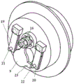
FIG. 1 is a top view of an automatic temperature control valve according to one embodiment of the present invention. FIG. 2 is a front view of an automatic temperature control valve according to one embodiment of the present invention. FIG. 3 is a schematic cross-sectional view of an automatic temperature control valve according to one embodiment of the present invention. As shown in fig. 1-3, the present invention provides an automatic temperature control valve comprising a housing 1 and a valve body assembly. The shell 1 is internally provided with a containing cavity, and is provided with a liquid inlet 2 and a liquid outlet 3 which are communicated with the containing cavity. The valve body assembly is arranged in the containing cavity and is used for dividing the containing cavity into a valve upper cavity 6 and a valve lower cavity 7, the valve upper cavity 6 is communicated with the liquid inlet 2, and the valve lower cavity 7 is communicated with the liquid outlet 3. FIG. 4 is a top view of a valve body assembly of an automatic temperature control valve according to one embodiment of the present invention. Fig. 5 is a schematic structural view of a valve body assembly of an automatic temperature control valve according to still another embodiment of the present invention. As shown in fig. 4 and 5, the valve body assembly includes a valve body base 4, a valve core assembly 17 (shown in fig. 6), a first limit assembly 19 and a second limit assembly 20. The valve body base 4 is provided with a through hole 10 and a liquid passing hole 5 communicating the valve upper chamber 6 and the valve lower chamber 7. The valve core assembly 17 is arranged in the through hole 10 in a penetrating mode, one end of the valve core assembly 17 is provided with a valve plate 9 exposed out of the valve upper cavity 6, and the valve core assembly 17 is configured to rotate along the axis of the through hole 10, so that the valve plate 9 closes the liquid through hole 5 when rotating to the position of the liquid through hole 5. First spacing subassembly 19 and the second spacing subassembly 20 all set up in valve body base 4 and are close to one side of valve block 9 and lie in the both sides of valve block 9, and first spacing subassembly 19 and the second spacing subassembly 20 configure to and take place opposite direction's deformation when ambient temperature surpasss and predetermine the temperature to when making ambient temperature be less than and predetermine the temperature, first spacing subassembly 19 does not take place deformation and restriction valve block 9 so that the through-flow hole 5 is opened. When the ambient temperature exceeds the preset temperature, the first limiting assembly 19 deforms towards the direction close to the valve body base 4 to remove the limitation on the valve plate 9, and meanwhile, the second limiting assembly 20 deforms towards the direction far away from the valve body base 4 to limit the rotation of the valve plate 9, so that the liquid through hole 5 is closed. In one embodiment, the valve body base 4 is made of steel.
According to the scheme of this embodiment, through set up the first spacing subassembly and the spacing subassembly of second that can be according to ambient temperature reverse deformation on automatic temperature control valve, realize that the through-flow hole is opened when ambient temperature is less than preset temperature, the through-flow hole seals when ambient temperature exceedes preset temperature. Therefore, in practical application, the opening and closing of the automatic temperature control valve can be controlled only according to temperature change.
Fig. 6 is a schematic structural view of a valve cartridge assembly of an automatic temperature control valve according to another embodiment of the present invention. As shown in fig. 6, the valve core assembly 17 further includes a mounting post 8 and a helical fan blade 11. As shown in fig. 3, both ends of the mounting column 8 extend out of the through hole 10, one end close to the upper valve cavity 6 is provided with a first thread structure, one end close to the lower valve cavity 7 is provided with a second thread structure, and displacement of the valve core assembly 17 in the axial direction thereof is limited through cooperation of the first thread structure and the second thread structure with the nut. The spiral fan blade 11 is disposed on the middle portion of the outer wall of the mounting column 8, and is disposed according to a preset angle, and the spiral fan blade 11 rotates when receiving the driving force of the liquid flowing through the through hole 10, so that the valve core assembly 17 rotates along with the rotation of the spiral fan blade 11. In one embodiment, a boss may also be provided on the end of the spool assembly 17 protruding into the lower valve chamber 7 to limit the displacement of the spool assembly 17 in the axial direction thereof.
According to the scheme of this embodiment, the spiral fan blade 11 is arranged on the valve core assembly 17, and the spiral fan blade 11 is arranged according to a preset angle so that the spiral fan blade can rotate when being pushed by fluid, so as to drive the valve plate 9 to rotate. It can be seen that the automatic temperature control valve in this embodiment is a pure mechanical structure, and the driving force of the rotation of the spiral fan blade 11 comes from the pushing of the fluid. Of course, in other embodiments, a motor may be used to drive the valve plate 9 to rotate to open and close the fluid hole.
Fig. 7 is a schematic structural view of a first metal component of an automatic temperature control valve according to still another embodiment of the present invention. As shown in fig. 7, the first stopper member 19 includes a first stopper protrusion 21 and two metal sheets 25 and 26 of different materials. The thermal deformation amount of the metal 26 close to the valve upper cavity 6 is larger than that of the metal 25 close to the valve body base 4, so that the middle part of the metal 26 close to the valve upper cavity of the first limiting component 19 protrudes in the direction far away from the valve body base 4 when the ambient temperature exceeds the preset temperature, and the two ends of the metal 26 are close to the valve body base 4. The first limiting protrusion 21 is located at one end of the first limiting component 19, and the two ends of the first limiting component 19 move towards the valve body base 4 when approaching the valve body base 4, so that the valve sheet 9 is not limited. In one embodiment, the metal of the first stop assembly 19 adjacent the upper valve chamber 6 is copper and the metal adjacent the valve body base 4 is iron.
Optionally, the second position-limiting member 20 comprises two metal sheets made of different materials and the second position-limiting protrusion 22. It should be noted that fig. 6 may also be referred to as a second limiting component. The thermal deformation of the metal of the two metal sheets made of different materials, which is close to the valve upper cavity 6, is less than that of the metal close to the valve body base 4, so that the middle part of the metal of the second limiting component 20, which is close to the valve body base 4, protrudes towards the valve body base 4 when the ambient temperature exceeds the preset temperature, and the two ends of the metal are close to the direction far away from the valve body base 4. The second limiting protrusion 22 is located at one end of the second limiting component 20, and moves in a direction away from the valve body base 4 when two ends of the second limiting component 20 approach in a direction away from the valve body base 4, so as to limit the rotation of the valve plate 9. Preferably, the two metal sheets of different materials on the first limiting component 19 and the second limiting component 20 are bonded together by strong glue. In one embodiment, the metal of the first stop assembly 19 adjacent the upper valve chamber 6 is iron and the metal adjacent the valve body base 4 is copper.
In a preferred embodiment, when the ambient temperature is lower than the preset temperature, neither the first limiting assembly nor the second limiting assembly deforms, the first limiting assembly is configured to be capable of being matched with the valve plate to limit the rotation of the valve plate when the ambient temperature is lower than the preset temperature, and the second limiting assembly is configured to not limit the rotation of the valve plate when the ambient temperature is lower than the preset temperature. The above function can be realized by setting the distance between the first limit component and the valve body base to be greater than the distance between the second limit component and the valve body base. In this embodiment, the valve plate rotates in the following order as the ambient temperature changes from low to high to low: 1. when the environment temperature is lower than the preset temperature, the valve plate rotates anticlockwise until the valve plate contacts the first limiting assembly to be limited, and the valve plate stops rotating; 2. when the ambient temperature exceeds the preset temperature, the first limiting assembly deforms towards the valve body base and removes the limitation on the valve sheet, at the moment, the valve sheet continues to rotate anticlockwise until the valve sheet is limited by contacting with the second limiting assembly which deforms towards the direction far away from the valve body base due to the rise of the ambient temperature, and the valve sheet stops rotating; 3. when the environment temperature is lower than the preset temperature, the first limiting assembly and the second limiting assembly recover, the limit of the second limiting assembly on the valve plate is removed, the valve plate continues to rotate anticlockwise until the valve plate contacts the first limiting assembly and is limited, and the valve plate stops rotating. The operation is repeated in a circulating way.
In one embodiment, the preset temperature may be any one of 20 ℃ to 50 ℃.
In one embodiment, the first stop assembly 19 and the second stop assembly 20 are each secured to the valve body base 4 by a mounting nut 24.
Optionally, as shown in fig. 4, the valve plate includes a main body and a limiting structure 23. The main body is of a wafer structure. Limiting structure 23 is arranged on the circumference of the main body, and limiting structure 23 is matched with first limiting protrusion 21 and second limiting protrusion 22 to control rotation of valve plate 9. In one embodiment, the valve plate 9 is mounted to the valve core assembly 17 by a nut 16. It should be noted that the valve plate 9 can rotate around the mounting portion after being mounted, so as to open and close the fluid hole. In one embodiment, two nuts placed on either side of the valve plate can be provided to secure the valve plate to the valve core assembly 17, with the two nuts adjusting and tightening the valve plate. And the position of the valve plate in the axial direction can be adjusted as required by arranging the two nuts.
It should be noted that, the height of the first limiting protrusion 21 may be greater than the height of the second limiting protrusion 22, so that when the ambient temperature is lower than the preset temperature, the first limiting assembly 19 limits the rotation of the valve plate, and the second limiting assembly 20 does not limit the rotation of the valve plate.
Alternatively, as shown in fig. 3, the housing 1 includes a protrusion 14 provided inside the housing 1 for overlapping the valve body assembly. Accordingly, the valve body assembly is provided with a ring of overlap around its periphery which engages the extension 14. Fig. 8 is a schematic structural view of an automatic temperature control valve according to still another embodiment of the present invention. As shown in fig. 8, the automatic thermo-valve further includes a compression spring 15 provided in the valve upper chamber 6 for fixing the valve body assembly inside the housing 1.
Optionally, as shown in fig. 2, the housing 1 further comprises an upper end cover and a lower end cover, which are connected by bolts 12. Preferably, as shown in fig. 3, the housing 1 further includes a sealing ring 13 disposed between the upper end cap and the lower end cap for sealing the housing 1 to prevent the outflow of liquid inside the housing 1.
It should be noted that the mounting positions or structures of the first limiting component 19, the second limiting component 20, the first limiting protrusion 21, the second limiting protrusion 22, the limiting structure 23 and the spiral fan blade 11 in the above embodiments can be changed to rotate the valve plate clockwise, for example: for the first limiting component 19 and the second limiting component 20, the distance between the first limiting component 19 and the valve body base is smaller than the distance between the second limiting component 20 and the valve body base or the height of the first limiting protrusion 21 is smaller than the height of the second limiting protrusion 22, and accordingly, the limiting structure 23 can be arranged at the relative position as shown in fig. 4, and accordingly, the preset angle of the spiral fan blade 11 also needs to be changed to enable the spiral fan blade to rotate reversely when pushed by fluid, and finally the valve blade is driven to rotate clockwise.
Fig. 9 is a schematic structural view of a radiator for a steering system according to still another embodiment of the present invention. As shown in fig. 9, the present invention also provides a radiator for a steering system, including the above-described automatic temperature control valve 40, the first oil chamber 31, the second oil chamber 32, and a plurality of fins 33. A first oil inlet is formed in one end of the first oil chamber 31, a first oil outlet is formed in the other end of the first oil chamber 31, and hydraulic oil flows into the first oil chamber 31 through the first oil inlet. A second oil outlet is formed in one end of the second oil chamber 32, and hydraulic oil flows out through the second oil outlet. Each of the plurality of fins 33 communicates with the first oil chamber 31 and the second oil chamber 32. In one embodiment, the number of fins 33 is 5.
Preferably, the first oil chamber 31, the plurality of fins 33 and the second oil chamber 32 are fixed by two cross members 34, and the cross members 34 are solid plate members for stabilization.
The liquid inlet of the automatic temperature control valve 40 is communicated with the first oil cavity through a first oil outlet, and the liquid inlet is communicated with the first oil outlet.
In the embodiment, the radiator is configured such that when the ambient temperature is lower than a first preset temperature, the automatic temperature control valve is opened, and the hydraulic oil flows out to the oil outlet through the automatic temperature control valve; and when the ambient temperature exceeds a first preset temperature, the automatic temperature control valve is closed, and the hydraulic oil flows to the second oil cavity through the radiating fin. Through the setting of this embodiment, for hydraulic oil provides the binary channels, one is the main passageway through the passageway of fin, and one is the main passageway through the passageway of automatic temperature control valve, can realize that hydraulic oil low temperature is straight through and avoid the fin circulation resistance big, the not smooth problem of oil absorption, and high temperature effectively dispels the heat. By the arrangement, the radiator of the steering system is in a good operating environment, and the performance and the reliability of the radiator are improved.
When the ambient temperature is lower than the first preset temperature, hydraulic oil flows through the channel of the automatic temperature control valve in sequence: a first oil inlet of the first oil chamber 31, a first oil outlet of the first oil chamber 31, an oil inlet of the automatic temperature control valve, an upper valve chamber, a liquid through hole, a lower valve chamber and an oil outlet of the automatic temperature control valve.
When the ambient temperature exceeds a first preset temperature, hydraulic oil flows through the channels of the radiating fins in sequence: a first oil inlet of the first oil chamber 31, a first oil outlet of the first oil chamber 31, a cooling fin, the second oil chamber 32, and a second oil outlet of the second oil chamber 32.
When the radiator works, a certain amount of hydraulic oil flows through the through hole of the automatic temperature control valve under the pressure of oil suction, and the spiral fan blade is pushed to enable the mounting rod and the valve plate to rotate anticlockwise. When the temperature was less than first preset temperature, the rotation of valve block can be blockked to first spacing arch of first spacing subassembly, and the through-flow hole was opened this moment, because the flow resistance of fin passageway is big, and a large amount of hydraulic oil can flow into the oil-out from automatic temperature control valve's passageway, reduces the oil absorption resistance. When the temperature of the hydraulic oil exceeds the first preset temperature, the first limiting assembly deforms towards the valve body base to remove the limit of the valve block, then the valve block rotates anticlockwise continuously, the valve block is limited by the second limiting protrusion when the valve block rotates to the second limiting assembly, the valve block just blocks the liquid through hole, only a small amount of hydraulic oil flows through the through hole, and a large amount of hydraulic oil flows through the radiating fin channel under the action of oil absorption pressure to reach the second oil outlet, so that the effective radiating effect is achieved. When the temperature of the hydraulic oil is lower than the first preset temperature again, the second limiting assembly is deformed towards the valve body base to remove the limit of the valve plate, and then the valve plate continues to rotate anticlockwise until the valve plate contacts the first limiting assembly and is limited. The above process cycles back and forth with changes in temperature.
In one embodiment, the first preset temperature may be any one of 20 ℃ to 50 ℃.
Preferably, in one embodiment, the material of the main body portion of the heat sink is aluminum, which can increase the heat dissipation effect.
In particular, the invention also provides a vehicle comprising the radiator for the steering system. The heat dissipation plate can effectively dissipate heat at high temperature and solve the problems of large circulation resistance and unsmooth oil absorption of the heat dissipation plate at low temperature.
Thus, it should be appreciated by those skilled in the art that while a number of exemplary embodiments of the invention have been illustrated and described in detail herein, many other variations or modifications consistent with the principles of the invention may be directly determined or derived from the disclosure of the present invention without departing from the spirit and scope of the invention. Accordingly, the scope of the invention should be understood and interpreted to cover all such other variations or modifications.