CN111225596B - Means and methods for vaginal route - Google Patents
Means and methods for vaginal route Download PDFInfo
- Publication number
- CN111225596B CN111225596B CN201880067375.6A CN201880067375A CN111225596B CN 111225596 B CN111225596 B CN 111225596B CN 201880067375 A CN201880067375 A CN 201880067375A CN 111225596 B CN111225596 B CN 111225596B
- Authority
- CN
- China
- Prior art keywords
- cannula
- kit
- dilator
- longitudinal axis
- sleeve
- Prior art date
- Legal status (The legal status is an assumption and is not a legal conclusion. Google has not performed a legal analysis and makes no representation as to the accuracy of the status listed.)
- Active
Links
Images


Classifications
-
- A—HUMAN NECESSITIES
- A61—MEDICAL OR VETERINARY SCIENCE; HYGIENE
- A61B—DIAGNOSIS; SURGERY; IDENTIFICATION
- A61B17/00—Surgical instruments, devices or methods, e.g. tourniquets
- A61B17/34—Trocars; Puncturing needles
- A61B17/3494—Trocars; Puncturing needles with safety means for protection against accidental cutting or pricking, e.g. limiting insertion depth, pressure sensors
- A61B17/3496—Protecting sleeves or inner probes; Retractable tips
-
- A—HUMAN NECESSITIES
- A61—MEDICAL OR VETERINARY SCIENCE; HYGIENE
- A61B—DIAGNOSIS; SURGERY; IDENTIFICATION
- A61B1/00—Instruments for performing medical examinations of the interior of cavities or tubes of the body by visual or photographical inspection, e.g. endoscopes; Illuminating arrangements therefor
- A61B1/00131—Accessories for endoscopes
- A61B1/00137—End pieces at either end of the endoscope, e.g. caps, seals or forceps plugs
-
- A—HUMAN NECESSITIES
- A61—MEDICAL OR VETERINARY SCIENCE; HYGIENE
- A61B—DIAGNOSIS; SURGERY; IDENTIFICATION
- A61B1/00—Instruments for performing medical examinations of the interior of cavities or tubes of the body by visual or photographical inspection, e.g. endoscopes; Illuminating arrangements therefor
- A61B1/00147—Holding or positioning arrangements
- A61B1/00154—Holding or positioning arrangements using guiding arrangements for insertion
-
- A—HUMAN NECESSITIES
- A61—MEDICAL OR VETERINARY SCIENCE; HYGIENE
- A61B—DIAGNOSIS; SURGERY; IDENTIFICATION
- A61B1/00—Instruments for performing medical examinations of the interior of cavities or tubes of the body by visual or photographical inspection, e.g. endoscopes; Illuminating arrangements therefor
- A61B1/005—Flexible endoscopes
- A61B1/01—Guiding arrangements therefore
-
- A—HUMAN NECESSITIES
- A61—MEDICAL OR VETERINARY SCIENCE; HYGIENE
- A61B—DIAGNOSIS; SURGERY; IDENTIFICATION
- A61B1/00—Instruments for performing medical examinations of the interior of cavities or tubes of the body by visual or photographical inspection, e.g. endoscopes; Illuminating arrangements therefor
- A61B1/313—Instruments for performing medical examinations of the interior of cavities or tubes of the body by visual or photographical inspection, e.g. endoscopes; Illuminating arrangements therefor for introducing through surgical openings, e.g. laparoscopes
-
- A—HUMAN NECESSITIES
- A61—MEDICAL OR VETERINARY SCIENCE; HYGIENE
- A61B—DIAGNOSIS; SURGERY; IDENTIFICATION
- A61B17/00—Surgical instruments, devices or methods, e.g. tourniquets
- A61B17/00234—Surgical instruments, devices or methods, e.g. tourniquets for minimally invasive surgery
-
- A—HUMAN NECESSITIES
- A61—MEDICAL OR VETERINARY SCIENCE; HYGIENE
- A61B—DIAGNOSIS; SURGERY; IDENTIFICATION
- A61B17/00—Surgical instruments, devices or methods, e.g. tourniquets
- A61B17/02—Surgical instruments, devices or methods, e.g. tourniquets for holding wounds open; Tractors
- A61B17/0218—Surgical instruments, devices or methods, e.g. tourniquets for holding wounds open; Tractors for minimally invasive surgery
-
- A—HUMAN NECESSITIES
- A61—MEDICAL OR VETERINARY SCIENCE; HYGIENE
- A61B—DIAGNOSIS; SURGERY; IDENTIFICATION
- A61B17/00—Surgical instruments, devices or methods, e.g. tourniquets
- A61B17/34—Trocars; Puncturing needles
- A61B17/3417—Details of tips or shafts, e.g. grooves, expandable, bendable; Multiple coaxial sliding cannulas, e.g. for dilating
- A61B17/3421—Cannulas
- A61B17/3423—Access ports, e.g. toroid shape introducers for instruments or hands
-
- A—HUMAN NECESSITIES
- A61—MEDICAL OR VETERINARY SCIENCE; HYGIENE
- A61B—DIAGNOSIS; SURGERY; IDENTIFICATION
- A61B17/00—Surgical instruments, devices or methods, e.g. tourniquets
- A61B17/34—Trocars; Puncturing needles
- A61B17/3462—Trocars; Puncturing needles with means for changing the diameter or the orientation of the entrance port of the cannula, e.g. for use with different-sized instruments, reduction ports, adapter seals
-
- A—HUMAN NECESSITIES
- A61—MEDICAL OR VETERINARY SCIENCE; HYGIENE
- A61B—DIAGNOSIS; SURGERY; IDENTIFICATION
- A61B17/00—Surgical instruments, devices or methods, e.g. tourniquets
- A61B17/34—Trocars; Puncturing needles
- A61B17/3494—Trocars; Puncturing needles with safety means for protection against accidental cutting or pricking, e.g. limiting insertion depth, pressure sensors
-
- A—HUMAN NECESSITIES
- A61—MEDICAL OR VETERINARY SCIENCE; HYGIENE
- A61B—DIAGNOSIS; SURGERY; IDENTIFICATION
- A61B17/00—Surgical instruments, devices or methods, e.g. tourniquets
- A61B17/34—Trocars; Puncturing needles
- A61B17/3498—Valves therefor, e.g. flapper valves, slide valves
-
- A—HUMAN NECESSITIES
- A61—MEDICAL OR VETERINARY SCIENCE; HYGIENE
- A61B—DIAGNOSIS; SURGERY; IDENTIFICATION
- A61B17/00—Surgical instruments, devices or methods, e.g. tourniquets
- A61B17/42—Gynaecological or obstetrical instruments or methods
-
- A—HUMAN NECESSITIES
- A61—MEDICAL OR VETERINARY SCIENCE; HYGIENE
- A61B—DIAGNOSIS; SURGERY; IDENTIFICATION
- A61B17/00—Surgical instruments, devices or methods, e.g. tourniquets
- A61B17/42—Gynaecological or obstetrical instruments or methods
- A61B17/4241—Instruments for manoeuvring or retracting the uterus, e.g. during laparoscopic surgery
-
- A—HUMAN NECESSITIES
- A61—MEDICAL OR VETERINARY SCIENCE; HYGIENE
- A61B—DIAGNOSIS; SURGERY; IDENTIFICATION
- A61B34/00—Computer-aided surgery; Manipulators or robots specially adapted for use in surgery
- A61B34/30—Surgical robots
-
- A—HUMAN NECESSITIES
- A61—MEDICAL OR VETERINARY SCIENCE; HYGIENE
- A61B—DIAGNOSIS; SURGERY; IDENTIFICATION
- A61B90/00—Instruments, implements or accessories specially adapted for surgery or diagnosis and not covered by any of the groups A61B1/00 - A61B50/00, e.g. for luxation treatment or for protecting wound edges
- A61B90/50—Supports for surgical instruments, e.g. articulated arms
-
- A—HUMAN NECESSITIES
- A61—MEDICAL OR VETERINARY SCIENCE; HYGIENE
- A61M—DEVICES FOR INTRODUCING MEDIA INTO, OR ONTO, THE BODY; DEVICES FOR TRANSDUCING BODY MEDIA OR FOR TAKING MEDIA FROM THE BODY; DEVICES FOR PRODUCING OR ENDING SLEEP OR STUPOR
- A61M29/00—Dilators with or without means for introducing media, e.g. remedies
- A61M29/02—Dilators made of swellable material
-
- A—HUMAN NECESSITIES
- A61—MEDICAL OR VETERINARY SCIENCE; HYGIENE
- A61B—DIAGNOSIS; SURGERY; IDENTIFICATION
- A61B17/00—Surgical instruments, devices or methods, e.g. tourniquets
- A61B17/00234—Surgical instruments, devices or methods, e.g. tourniquets for minimally invasive surgery
- A61B2017/00238—Type of minimally invasive operation
- A61B2017/00278—Transorgan operations, e.g. transgastric
-
- A—HUMAN NECESSITIES
- A61—MEDICAL OR VETERINARY SCIENCE; HYGIENE
- A61B—DIAGNOSIS; SURGERY; IDENTIFICATION
- A61B17/00—Surgical instruments, devices or methods, e.g. tourniquets
- A61B2017/00367—Details of actuation of instruments, e.g. relations between pushing buttons, or the like, and activation of the tool, working tip, or the like
- A61B2017/00398—Details of actuation of instruments, e.g. relations between pushing buttons, or the like, and activation of the tool, working tip, or the like using powered actuators, e.g. stepper motors, solenoids
-
- A—HUMAN NECESSITIES
- A61—MEDICAL OR VETERINARY SCIENCE; HYGIENE
- A61B—DIAGNOSIS; SURGERY; IDENTIFICATION
- A61B17/00—Surgical instruments, devices or methods, e.g. tourniquets
- A61B2017/0042—Surgical instruments, devices or methods, e.g. tourniquets with special provisions for gripping
-
- A—HUMAN NECESSITIES
- A61—MEDICAL OR VETERINARY SCIENCE; HYGIENE
- A61B—DIAGNOSIS; SURGERY; IDENTIFICATION
- A61B17/00—Surgical instruments, devices or methods, e.g. tourniquets
- A61B2017/00982—General structural features
- A61B2017/00991—Telescopic means
-
- A—HUMAN NECESSITIES
- A61—MEDICAL OR VETERINARY SCIENCE; HYGIENE
- A61B—DIAGNOSIS; SURGERY; IDENTIFICATION
- A61B17/00—Surgical instruments, devices or methods, e.g. tourniquets
- A61B17/28—Surgical forceps
- A61B17/29—Forceps for use in minimally invasive surgery
- A61B2017/2901—Details of shaft
- A61B2017/2906—Multiple forceps
-
- A—HUMAN NECESSITIES
- A61—MEDICAL OR VETERINARY SCIENCE; HYGIENE
- A61B—DIAGNOSIS; SURGERY; IDENTIFICATION
- A61B17/00—Surgical instruments, devices or methods, e.g. tourniquets
- A61B17/34—Trocars; Puncturing needles
- A61B17/3417—Details of tips or shafts, e.g. grooves, expandable, bendable; Multiple coaxial sliding cannulas, e.g. for dilating
- A61B17/3421—Cannulas
- A61B2017/3443—Cannulas with means for adjusting the length of a cannula
-
- A—HUMAN NECESSITIES
- A61—MEDICAL OR VETERINARY SCIENCE; HYGIENE
- A61B—DIAGNOSIS; SURGERY; IDENTIFICATION
- A61B17/00—Surgical instruments, devices or methods, e.g. tourniquets
- A61B17/34—Trocars; Puncturing needles
- A61B17/3417—Details of tips or shafts, e.g. grooves, expandable, bendable; Multiple coaxial sliding cannulas, e.g. for dilating
- A61B17/3421—Cannulas
- A61B2017/3445—Cannulas used as instrument channel for multiple instruments
-
- A—HUMAN NECESSITIES
- A61—MEDICAL OR VETERINARY SCIENCE; HYGIENE
- A61B—DIAGNOSIS; SURGERY; IDENTIFICATION
- A61B17/00—Surgical instruments, devices or methods, e.g. tourniquets
- A61B17/34—Trocars; Puncturing needles
- A61B17/3417—Details of tips or shafts, e.g. grooves, expandable, bendable; Multiple coaxial sliding cannulas, e.g. for dilating
- A61B17/3421—Cannulas
- A61B2017/345—Cannulas for introduction into a natural body opening
- A61B2017/3452—Cannulas for introduction into a natural body opening for the rectum, e.g. for hemorrhoid surgery
-
- A—HUMAN NECESSITIES
- A61—MEDICAL OR VETERINARY SCIENCE; HYGIENE
- A61B—DIAGNOSIS; SURGERY; IDENTIFICATION
- A61B17/00—Surgical instruments, devices or methods, e.g. tourniquets
- A61B17/34—Trocars; Puncturing needles
- A61B17/3417—Details of tips or shafts, e.g. grooves, expandable, bendable; Multiple coaxial sliding cannulas, e.g. for dilating
- A61B2017/3454—Details of tips
- A61B2017/3456—Details of tips blunt
-
- A—HUMAN NECESSITIES
- A61—MEDICAL OR VETERINARY SCIENCE; HYGIENE
- A61B—DIAGNOSIS; SURGERY; IDENTIFICATION
- A61B17/00—Surgical instruments, devices or methods, e.g. tourniquets
- A61B17/34—Trocars; Puncturing needles
- A61B17/3462—Trocars; Puncturing needles with means for changing the diameter or the orientation of the entrance port of the cannula, e.g. for use with different-sized instruments, reduction ports, adapter seals
- A61B2017/3466—Trocars; Puncturing needles with means for changing the diameter or the orientation of the entrance port of the cannula, e.g. for use with different-sized instruments, reduction ports, adapter seals for simultaneous sealing of multiple instruments
-
- A—HUMAN NECESSITIES
- A61—MEDICAL OR VETERINARY SCIENCE; HYGIENE
- A61B—DIAGNOSIS; SURGERY; IDENTIFICATION
- A61B17/00—Surgical instruments, devices or methods, e.g. tourniquets
- A61B17/42—Gynaecological or obstetrical instruments or methods
- A61B2017/4216—Operations on uterus, e.g. endometrium
-
- A—HUMAN NECESSITIES
- A61—MEDICAL OR VETERINARY SCIENCE; HYGIENE
- A61B—DIAGNOSIS; SURGERY; IDENTIFICATION
- A61B34/00—Computer-aided surgery; Manipulators or robots specially adapted for use in surgery
- A61B34/30—Surgical robots
- A61B2034/301—Surgical robots for introducing or steering flexible instruments inserted into the body, e.g. catheters or endoscopes
-
- A—HUMAN NECESSITIES
- A61—MEDICAL OR VETERINARY SCIENCE; HYGIENE
- A61B—DIAGNOSIS; SURGERY; IDENTIFICATION
- A61B34/00—Computer-aided surgery; Manipulators or robots specially adapted for use in surgery
- A61B34/30—Surgical robots
- A61B2034/302—Surgical robots specifically adapted for manipulations within body cavities, e.g. within abdominal or thoracic cavities
-
- A—HUMAN NECESSITIES
- A61—MEDICAL OR VETERINARY SCIENCE; HYGIENE
- A61B—DIAGNOSIS; SURGERY; IDENTIFICATION
- A61B90/00—Instruments, implements or accessories specially adapted for surgery or diagnosis and not covered by any of the groups A61B1/00 - A61B50/00, e.g. for luxation treatment or for protecting wound edges
- A61B90/03—Automatic limiting or abutting means, e.g. for safety
- A61B2090/033—Abutting means, stops, e.g. abutting on tissue or skin
- A61B2090/034—Abutting means, stops, e.g. abutting on tissue or skin abutting on parts of the device itself
-
- A—HUMAN NECESSITIES
- A61—MEDICAL OR VETERINARY SCIENCE; HYGIENE
- A61B—DIAGNOSIS; SURGERY; IDENTIFICATION
- A61B90/00—Instruments, implements or accessories specially adapted for surgery or diagnosis and not covered by any of the groups A61B1/00 - A61B50/00, e.g. for luxation treatment or for protecting wound edges
- A61B90/06—Measuring instruments not otherwise provided for
- A61B2090/061—Measuring instruments not otherwise provided for for measuring dimensions, e.g. length
-
- A—HUMAN NECESSITIES
- A61—MEDICAL OR VETERINARY SCIENCE; HYGIENE
- A61B—DIAGNOSIS; SURGERY; IDENTIFICATION
- A61B90/00—Instruments, implements or accessories specially adapted for surgery or diagnosis and not covered by any of the groups A61B1/00 - A61B50/00, e.g. for luxation treatment or for protecting wound edges
- A61B90/08—Accessories or related features not otherwise provided for
- A61B2090/0807—Indication means
- A61B2090/0811—Indication means for the position of a particular part of an instrument with respect to the rest of the instrument, e.g. position of the anvil of a stapling instrument
-
- A—HUMAN NECESSITIES
- A61—MEDICAL OR VETERINARY SCIENCE; HYGIENE
- A61B—DIAGNOSIS; SURGERY; IDENTIFICATION
- A61B90/00—Instruments, implements or accessories specially adapted for surgery or diagnosis and not covered by any of the groups A61B1/00 - A61B50/00, e.g. for luxation treatment or for protecting wound edges
- A61B90/50—Supports for surgical instruments, e.g. articulated arms
- A61B2090/508—Supports for surgical instruments, e.g. articulated arms with releasable brake mechanisms
Abstract
Trocar assemblies and methods of use are described in which a trocar assembly is configured to provide access to an intra-peritoneal space through a rectouterine pouch to a surgical tool, optionally including one or more surgical robotic components. The diameter of the surgical tool may optionally be 5mm or greater. In some embodiments, the cannula portion has an inner lumen sized to provide access to a plurality of surgical tools via the rectouterine pouch and simultaneously transvaginally into the intra-peritoneal space. In some embodiments, one or two dilators are optionally used, forming an incision sized to receive the distal aperture of the cannula. The dilator may be sized to form (optionally, starting with a needle of 2mm or less in diameter) a rectangular hole. In some embodiments, the width of the rectangular aperture in the major axis is at least twice the width in the minor axis.
Description
Disclosure of Invention
According to some specific embodiments of the present invention, there is provided a stepped dilator for use with a trocar kit to provide abdominal access via a body recess, comprising: an expander body having a longitudinal axis in a proximal to distal direction; a first tapered region of the dilator body that tapers towards a distal end of the dilator body; a second tapered region of the dilator body tapering in a distal direction away from the first tapered region and separated from the first tapered region by an isolation region.
In some particular embodiments, the isolation region comprises a region of constant cross-section perpendicular to a longitudinal axis extending between the first tapered region and the second tapered region.
In some embodiments, the isolation zone comprises a region having no cross-section perpendicular to the longitudinal axis in any direction other than the largest cross-section perpendicular to the longitudinal axis of the first tapered region.
In some embodiments, the length of the isolation region is at least 3 mm.
In some embodiments, the length of the isolation region is no greater than 20 mm.
In some embodiments, the length of the isolation zone is 5-15 mm.
In some embodiments, the overall taper range of at least one of the first tapered region and the second tapered region tapers between its smallest cross-section and its largest cross-section, and the largest cross-section perpendicular to the longitudinal axis is 15mm or less above the longitudinal distance.
In some particular embodiments, the diameter of the step dilator perpendicular to the longitudinal axis is increased by at least 7.5mm by the taper range of at least one of the first tapered region and the second tapered region.
In some embodiments, the cross-section of the first tapered region having the largest cross-section perpendicular to the longitudinal axis has at least one axis of about 10mm or more.
In some embodiments, the distal tip of the first tapered region comprises 4mm2Or smaller anterior surface aperture and expands in a distal direction from the anterior surface aperture through a radius of curvature of at least 2.5 mm.
In some embodiments, the front surface aperture is an aperture of the lumen that is sized to allow a trocar having a diameter of less than or equal to about 2mm to be partially advanced through the aperture in the longitudinal direction.
In some embodiments, the cross-section of the first tapered region having the largest cross-section perpendicular to the longitudinal axis has at least one axis of about 7.5mm or more.
According to some embodiments of the present invention, there is provided a kit comprising the stepped dilator of claim 1, and further a handle and trocar; wherein the step dilator and handle together define an inner lumen sized to receive the trocar leading from the proximal end of the handle to the distal tip of the step dilator.
In some embodiments, the trocar is provided with a handle that extends at least 5cm beyond a distal end of the handle when a distal tip of the trocar is advanced 5mm beyond a distal tip of the step dilator.
In some embodiments, the trocar is provided as a sharpened, internal, spring-loaded core for use as a puncture needle having an extended position and a collapsed position; the die includes: a blunt end that extends beyond a sharp tip of the trocar in the extended position and prevents the sharp tip from damaging tissue; and the tubular core is moved to the folded position when sufficient longitudinal force is applied such that it no longer extends through the sharp tip, allowing the sharp tip to be operable to penetrate tissue.
In some embodiments, the kit is provided with a stop arrangement configured to block advancement of the distal tip of the trocar greater than 5mm beyond the distal tip of the stepped dilator.
In some embodiments, the cross-section of the second conical region having the largest cross-section perpendicular to the longitudinal axis has at least one axis of about 21mm or more.
According to some embodiments of the present invention, a cannula for providing abdominal access via a wall of a body recess is provided. In the cannula, a cross-section of the lumen of the cannula transverse to the longitudinal axis of the cannula has a major axis and a minor axis, and wherein the length of the major axis is at least twice the length of the minor axis.
In some embodiments, the length of the minor axis is between 5mm and 10 mm.
In some embodiments, the length of the major axis is between 10mm and 30 mm.
In some embodiments, the lumen wall defining the cross-section of the cannula comprises straight sections on opposite sides of the cross-section.
In some embodiments, the straight sections are interconnected through a curved section.
In some embodiments, the length of the cannula is at least 5 cm.
In some embodiments, the edge of the aperture defined at the distal end of the cannula comprises: a first edge portion extending along one side of the hole, and a second edge portion extending along another side of the hole, wherein the first edge portion extends to a further side than the second edge portion along the longitudinal axis.
In some embodiments, the first edge portion and the second edge portion extend along opposite sides of the aperture.
In some embodiments, the first edge portion and the second edge portion extend along the long cross-sectional axis.
In some embodiments, the cannula includes a handle extending at least 10cm from the proximal end of the cannula.
According to some embodiments of the present invention, there is provided a cannula for use with a trocar to provide access to an abdominal cavity via a body recess, characterized by: an edge of the aperture defined at the distal end of the cannula includes: a first edge portion extending along one side of the hole, and a second edge portion extending along another side of the hole, wherein the first edge portion extends to a further side than the second edge portion along the longitudinal axis.
In some specific embodiments, the first edge portion is positioned at least 5mm further than the second edge portion.
In some embodiments, each of the first edge portion and the second edge portion includes a respective straight section.
According to some specific embodiments of the present invention, there is provided a method of using a cannula to provide abdominal access to a body depression via the body depression, the method comprising: inserting the distal end of the cannula into the dilated hole of the rectouterine pouch via a transvaginal approach; wherein an edge of the aperture defined at the distal end of the cannula comprises: a first edge portion extending along one side of the hole, and a second edge portion extending along another side of the hole, wherein the first edge portion is positioned to extend further along the sleeve and further from the expanded hole than the second edge portion; and wherein the sleeve is inserted such that the hole at the distal end of the sleeve is oriented to open towards the side of the second edge portion and to face the rectum adjacent to the rectouterine pouch.
In some embodiments, the method comprises: inserting a flexible mechanical arm through the cannula into the rectouterine pouch so that it exits the hole in a direction away from the rectum.
In some embodiments, inserting the distal end of the cannula into the rectouterine pouch comprises sliding the cannula over an outer dilator; the outer dilator having a tapered distal insertion end sized and shaped to slide over an inner dilator having a tapered distal insertion end, the inner dilator having a rounded tip; the sleeve is fittingly slid over the outer dilator; and at least the external dilator is inserted into the rectouterine pouch via the transvaginal route.
In some embodiments, the method comprises: sliding the sleeve over the outer dilator while the inner dilator remains within the outer dilator.
In some embodiments, inserting the distal end of the cannula into the rectouterine pouch comprises sliding the cannula over a stepped dilator; the stepped dilator has a tapered distal insertion end with a rounded tip, a second tapered region, and an isolation region between the second tapered region and the tapered distal insertion end; the sleeve matingly slides over the stepped dilator; and the dilator is inserted into the rectouterine pouch by a transvaginal route.
In some embodiments, the rounded tip has an aperture sized to pass through a trocar having a diameter of less than or equal to about 2 mm.
According to some specific embodiments of the present invention, there is provided a kit for providing abdominal access via a body depression, comprising: a cannula, wherein a cross-section of the lumen of the cannula transverse to the longitudinal axis of the cannula has an axis long enough to allow simultaneous insertion of at least two cylindrical members, each cylindrical member having a diameter of at least 8 mm; a stepped dilator having a dilator body with: a first tapered region of the dilator body that tapers toward a distal end of the dilator body; and a second tapered region of the dilator body that tapers in a distal direction, is proximal to the first tapered region, and is separated from the first tapered region by an isolation region; a trocar provided with a handle region that extends beyond a proximal end of an inner dilator when a distal tip of the trocar is advanced to a distal tip of the inner dilator.
In some embodiments, the length of the long axis of the cross-section of the cannula lumen is at least 21 mm.
In some embodiments, the sleeve has a short cross-sectional axis; the length of the long cross-sectional axis is at least twice the length of the short cross-sectional axis.
In some embodiments, the kit comprises: an arm sheath for a plurality of robotic arms sized to have a minimum diameter of about 10mm and a maximum diameter of at least twice the minimum diameter to fit within the sheath.
According to some embodiments of the present invention, there is provided a method of gaining access to the abdominal cavity through a body depression, comprising: inserting a first step of a stepped dilator into a rectouterine pouch to widen a hole in a wall of the rectouterine pouch; and inserting the second step of the stepped dilator into the rectouterine pouch to widen the hole; wherein the first step and the second step of the stepped dilator each comprise a region that narrows in a distal direction, and wherein the first step and the second step of the stepped dilator are separated by an isolation region of at least 3mm length.
In some embodiments, the method is performed after: inserting the stepped dilator laterally into a wall of the rectouterine pouch; and advancing a trocar from within the stepped dilator to create the hole in the wall of the rectouterine pouch.
In some embodiments, the lumen of the cannula has at least one cross-sectional axis that is 20mm long.
In some embodiments, the lumen of the cannula has at least one cross-sectional axis that is about 12mm long.
According to some embodiments of the present invention, there is provided a method of gaining access to the abdominal cavity through a body depression, comprising: inserting the camera into the intra-abdominal space with the wall of the rectouterine pouch in the field of view of the camera; illuminating the wall of the rectouterine pouch with an abdominally located illumination device; selecting a location of a hole in the wall of the rectouterine pouch based on light from the illumination device visible from outside the rectouterine pouch; advancing a trocar from outside the rectouterine pouch to press against a selected location in the wall of the rectouterine pouch; verifying a position of the trocar based on one or more images from the camera within the intra-peritoneal space; and piercing the rectouterine pouch with the trocar to pass through the hole.
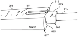
According to some specific embodiments of the present invention, there is provided a kit for setting a position of a robot arm system along a longitudinal axis of a cannula inserted into a body orifice, wherein the robot arm system comprises a motor unit and at least one robot arm positioned away from the motor unit along the longitudinal axis, the kit comprising: a cannula comprising a cannula body configured for insertion into the body orifice; a mounting block configured for attachment to the cannula; and an assembly attached to the mounting block and including a spacer arm and an alignment arm and movable between a stowed position and a deployed position; wherein the deployed position of the assembly in which the assembly indicates a predetermined position along the longitudinal axis places elements of the alignment arm.
In some embodiments, the mounting block is attached to the cannula by connecting to an access device having a lumen sized to matingly receive the cannula therein.
In some embodiments, the spacer arm and the alignment arm are arranged by articulation about a plurality of stop hinges, each stop hinge defining at least one stopped deployed position and a stopped stowed position.
In some embodiments, the kit further comprises: the motor unit and the at least one robotic arm extend distally from the motor unit to a predetermined distance from a stop receptacle of the motor unit; wherein when the at least one robotic arm is inserted into the cannula, the distal end of the at least one robotic arm is aligned with the distal end of the cannula and the stop portion of the alignment arm contacts the stop-receiver of the motor unit to prevent longitudinal advancement of the motor unit.
In some embodiments, the kit comprises: an arm guard having an inner cavity sized to receive the at least one robotic arm; and an outer surface sized to fit within the sleeve.
According to some specific embodiments of the present invention, there is provided an inner dilator for use with a trocar kit to provide abdominal access via a body recess, having a distal insertion end with a longitudinal distance of 15mm or less between a distal tip and a fully expanded cross-section of the inner dilator, wherein: the fully expanded cross-section of the inner dilator has at least one axis of about 10mm or more; the distal tip of the insertion end comprises 4mm2Or a smaller front surface aperture, and a distal tip of the insertion end expands along the taper from the front surface aperture through a radius of curvature of at least 2.5 mm; and the front surface aperture is an aperture of the lumen that is sized to allow a trocar having a diameter of less than or equal to about 2mm to be partially advanced through the aperture in the longitudinal direction.
In some embodiments, the fully expanded cross-section of the inner dilator has at least one axis of about 7.5mm or less.
According to some embodiments of the present invention, there is provided a kit comprising the inner dilator described above, in conjunction with a trocar, wherein the inner dilator is at least 17cm in length and the trocar is provided with a handle extending at least 5cm beyond the proximal end of the inner dilator when the distal tip of the trocar is advanced 5mm beyond the distal tip of the inner dilator.
In some embodiments, the trocar is provided as a sharpened, internal, spring-loaded core for use as a puncture needle; wherein the tubular core in its extended position prevents the sharp tip of the trocar from damaging tissue, but when sufficient longitudinal force is applied, the tubular core collapses such that the sharp tip is operable to penetrate tissue.
In some embodiments, the kit is provided with a stop device configured to block advancement of the distal tip of the trocar beyond the distal tip of the step dilator by greater than 5 mm.
According to some specific embodiments of the present invention, there is provided a kit comprising the inner dilator described above, together with an outer dilator, wherein the outer dilator has a distal insertion end that tapers over a longitudinal distance between a distal opening and a fully expanded cross-section of the outer dilator, wherein the fully expanded cross-section of the inner dilator has at least one shaft of about 21mm or more.
In some embodiments, the distal opening has a lumen sized to cooperatively surround the fully expanded cross-section of the inner dilator.
In some embodiments, the kit is provided with a stop configured to block the distal tip of the outer dilator from advancing more than 15mm beyond the distal tip of the inner dilator.
According to some embodiments of the present invention, there is provided a trocar kit for providing access to an abdominal cavity via a body depression, comprising: a cannula having a lumen with a cross-section transverse to a longitudinal axis of the cannula having an axis long enough to allow simultaneous insertion of at least two cylindrical members, each cylindrical member having a diameter of at least 8 mm; the inner dilator is at least long enough to leave an outer treatment region of about 10cm while fully inserted into a body bore of length 7cm, and has a distal insertion end that tapers over a sufficiently short longitudinal distance to be 4mm2A full first step dilation is achieved in the movement between the distal tip of area or less and a fully dilated cross section of the inner dilator, wherein the fully dilated cross section of the inner dilator has at least one axis with a length of about half of the long axis of the cannula cross section; the trocar having a handle region extending beyond the proximal end of the inner dilator when the distal tip of the trocar is advanced to the distal tip of the inner dilator; and an outer dilator, wherein the outer dilator has a distal insertionAn entry end extending between a distal opening having a length of 15mm or less and a fully expanded cross-section of the outer dilator, wherein the fully expanded cross-section of the outer dilator is sized to be matingly encompassed by the lumen of the cannula.
In some embodiments, the length of the long cross-sectional axis of the cannula lumen is at least 21 mm.
In some embodiments, the sleeve has a short cross-sectional axis; the length of the long cross-sectional axis is at least twice the length of the short cross-sectional axis.
According to some embodiments of the present invention, there is provided a trocar kit for providing access to an abdominal cavity via a body depression, comprising: an inner dilator, an outer dilator, and a cannula; wherein: the outer dilator sized and shaped to be matingly inserted over the inner dilator; the cannula being sized and shaped to be fittingly inserted over the outer dilator; the inner dilator is provided having a rounded distal tip with an aperture sized for longitudinal passage of a trocar portion having a diameter less than or equal to about 2 mm; and the lumen of the cannula has at least one cross-sectional axis of at least 20 mm; and the lumen of the cannula has at least one cross-sectional axis of less than about 12 mm.
In some embodiments, the inner dilator and the outer dilator are each tapered along the longitudinal axis from a respective narrower distal insertion end to a respective full-size cross-section within 15 mm.
According to some embodiments of the present invention, there is provided a method of gaining access to the abdominal cavity through a body depression, comprising: inserting an inner dilator laterally onto the wall of the rectouterine pouch; advancing a trocar from within the inner dilator to create a hole in the wall of the rectouterine pouch; inserting the inner dilator, not exceeding 15mm in length, into the rectouterine pouch to widen the hole; inserting the distal end of the cannula into the rectouterine pouch by sliding the outer dilator over the inner dilator and through the hole while the hole is held open by the inner dilator; wherein the lumen of the cannula has at least one cross-sectional axis having a length of at least 20 mm.
In some embodiments, the lumen of the cannula has at least one cross-sectional axis of less than about 12 mm.
According to some embodiments of the present invention, there is provided a method of gaining access to the abdominal cavity through a body depression, comprising: inserting the camera into the intra-abdominal space with the wall of the rectouterine pouch in the field of view of the camera; illuminating the wall of the rectouterine pouch with an abdominally located illumination device; selecting a location of a hole in the wall of the rectouterine pouch based on light from the illumination device visible from outside the rectouterine pouch; advancing a trocar from outside of the rectouterine pouch to press against a selected location in the wall of the rectouterine pouch; verifying a position of the trocar based on one or more images from the camera within the intra-peritoneal space; and piercing the rectouterine pouch with the trocar to pass through the hole.
According to some specific embodiments of the present invention, there is provided a kit for setting a position of a robot arm system along a longitudinal axis of a cannula inserted into a body orifice, wherein the robot arm system comprises a motor unit and at least one robot arm positioned away from the motor unit along the longitudinal axis, the kit comprising: a cannula, comprising: a cannula body configured for insertion into the body orifice; and a cannula handle extending distally along a longitudinal axis of the cannula; a mounting block comprising: a mounting block body, and a clamp configured to clamp the cannula handle at a selected longitudinal position relative to the mounting block body; and a motor unit stop comprising a longitudinally extending member attached to the mounting block body and movable between a first position extending a predetermined length from the mounting block body to a proximal end of the motor unit stop and a second position; wherein the proximal end of the motor unit stop in the first position is positioned to contact and prevent longitudinal advancement of the motor unit when the at least one robotic arm is inserted into the cannula, thereby defining a predetermined longitudinal position of the robotic arm system relative to the cannula; and wherein the second position of the motor unit stop removes the motor unit stop proximal end from a position that prevents longitudinal advancement of the motor unit from the predetermined longitudinal position.
In some particular embodiments, the motor unit stop is attached to the mounting block body by a hinge, the first position comprises an orientation of the motor unit stop along a longitudinal axis of the cannula, and the movement between the first position and the second position comprises rotation of the motor unit stop on the hinge.
In some embodiments, the motor unit stop is movable between the first position and the second position, the at least one robotic arm not interfering with the position of the cannula or the motor unit when the at least one robotic arm is inserted into the cannula.
In some embodiments, the kit further comprises: a motor unit and at least one robotic arm extending distally from the motor unit to a predetermined distance from a stop receiving location of the motor unit; wherein when at least one robotic arm is inserted into the cannula, the distal end of the at least one robotic arm is aligned with the distal end of the cannula and the motor unit stop contacts the stop receiving location of the motor unit to prevent longitudinal advancement of the motor unit.
In some embodiments, the kit includes a plurality of extenders, each extender including a tube having a lumen cross-section sized to receive a robotic arm having a cross-sectional axis at least 7mm long, the length of the cross-sectional axis being set to extend longitudinally from the proximal end of the stopper to a position distal to the longitudinal position of the mounting block body.
In some embodiments, the mounting block body is an aperture that is inserted to receive a plurality of extenders in a position and orientation that allows the robotic arm to be guided along a longitudinal axis to the cannula body.
According to some specific embodiments of the present invention, there is provided a kit comprising: an inner dilator having a distal tip sized to partially dilate the incision, and an outer dilator sized to slide distally over the inner dilator to further dilate the incision with the distal tip of the outer dilator, wherein: the overall expansion of the inner and outer dilators is at least sufficient to allow for the simultaneous insertion of at least two cylindrical members, each cylindrical member having a diameter of at least about 8mm, and the longitudinal distance along each of the inner and outer dilators is less than about 20 mm; at least one of the inner and outer dilators is marked near the proximal end to indicate the relative position of the two dilators, including at least one mark indicating the alignment of the distal ends of the two dilators and a mark indicating the difference in longitudinal position of one dilator relative to the other at the longitudinal distance at which dilation occurs.
In some embodiments, the inner dilator and the outer dilator are both marked with a distance scale indicating the distance along each dilator to its distal end.
In some embodiments, the distance scales of the inner dilator and the outer dilator are digitally calibrated when the distal ends of each dilator are aligned.
In some embodiments, the kit comprises: an indicator indexer configured to vary a force required to longitudinally translate the inner and outer dilators as a function of their relative longitudinal positions.
Unless defined otherwise, all technical and/or scientific terms used herein have the same meaning as commonly understood by one of ordinary skill in the art to which this invention belongs. Although methods and materials similar or equivalent to those described herein can be used in the practice or testing of embodiments of the present invention, exemplary methods and/or materials are described below. In case of conflict, the patent specification, including definitions, will control. In addition, the materials, methods, and examples are illustrative only and not necessarily limiting.
Drawings
Some specific embodiments of the invention are described below, by way of example only, with reference to the accompanying drawings. In particular, reference will now be made in detail to the accompanying drawings, details of which are illustrated by way of example and for purposes of illustrative discussion. In this regard, it will be apparent to one skilled in the art how the embodiments of the invention may be practiced using the description taken in conjunction with the accompanying drawings.
In these drawings:
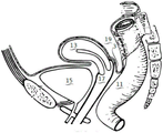
FIG. 1 is a schematic illustration of a portion of the human female pelvic anatomy, referenced herein, according to some embodiments of the invention.
Fig. 2A schematically illustrates a kit of trocar assemblies according to some embodiments of the present invention.
Fig. 2B schematically illustrates distal portions of components in a kit of trocar assemblies according to some specific embodiments of the present invention.
Fig. 3A-3H schematically illustrate methods of using a trocar assembly to establish an intraperitoneal pathway through the wall of the rectouterine pouch or another body wall, according to some specific embodiments of the invention.
Fig. 3I schematically illustrates the cannula configuration of fig. 3H and an inserted tool according to some embodiments of the invention.
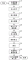
Fig. 3J is a schematic flow chart summarizing preparation for laparoscopic surgery using a trocar according to some embodiments of the present invention.
Figure 3K is a schematic flow chart illustrating a method of dilating and cannulating an access incision into a rectouterine pouch according to some embodiments of the present invention.
Fig. 3L schematically illustrates a wider view (compared to fig. 3H) of the positioning of a cannula according to some embodiments of the invention relative to the anatomy of the female lower abdominal/pelvic region.
Figure 4 schematically illustrates a dual verification method of positioning an incision for providing transvaginal access to a rectouterine pouch, according to some embodiments of the present invention.
Fig. 5A-5C schematically illustrate different stop mechanisms for trocar components according to some embodiments of the present invention.
Fig. 5D-5F schematically illustrate a needle, a needle holder and a needle handle according to some embodiments of the invention.
Fig. 5G-5I schematically illustrate mechanisms for controlling the relative positions of an inner dilator, an outer dilator, and a needle according to some specific embodiments of the present invention.
Fig. 5J is a flow chart that schematically outlines a method for establishing and maintaining a known penetration depth of a trocar, dilator, and/or cannula component using an indicator, according to some embodiments of the invention.
Fig. 5K illustrates an example of the manufacture of an expansion and sleeve assembly including the components described and illustrated in, for example, fig. 3A-3I and 5D-5I, according to some specific embodiments of the present invention.
Fig. 6A-6E schematically illustrate dilation using a single dilator trocar kit according to some embodiments of the present invention.
Figures 7A-7B are images taken of the interior of an insufflating abdomen of a robotic arm inserted through a cannula in a configuration similar to that of figure 3I according to some embodiments of the present invention.
Fig. 8A-8B illustrate dimensional features of an outer dilator and an inner dilator according to some specific embodiments of the present invention.
Fig. 9A-9D include views illustrating an instrument holder for a cannula and a use configuration thereof according to some embodiments of the present invention, wherein the instrument holder includes a motor unit stop for setting an initial robotic arm position.
Fig. 10A-10E schematically illustrate views representing a collapsed instrument holder for a cannula for setting an initial robotic arm position relative to the cannula and its configuration, in accordance with some specific embodiments of the present invention.
Fig. 10F-10J schematically illustrate components of a folding instrument holder, according to some embodiments of the present invention.
Fig. 11A-11E schematically illustrate a stepped dilator, dilator handle and trocar according to some embodiments of the present invention.
Figures 12A-12C schematically illustrate a duckbill gasket in accordance with some embodiments of the present invention for sealing a passage to a proximal bore of an access device.
Detailed Description
In some embodiments thereof, the present invention relates to the field of laparoscopic surgery, and more particularly, to devices and methods for laparoscopic access to the abdominal space.
SUMMARY
A broad aspect of some embodiments of the present invention relates to trocar components (individually and/or in kits) configured to provide an abdominal space for a surgical tool via a rectouterine pouch, optionally including one or more surgical robotic members (referred to herein as "robotic arms"). A rectouterine pouch access to the peritoneal space offers potential advantages over, for example, an umbilical access to the peritoneal space to reduce invasiveness, reduce patient trauma, reduce visible scarring, and/or speed of operation.
An aspect of some embodiments of the invention relates to a cannula having a lumen with an elliptical cross-section and configured to simultaneously receive two or more substantially cylindrical tools extending side-by-side along the lumen.
In some embodiments, a cannula member is provided having a longitudinal length sufficient to extend between the walls of the rectouterine pouch and a location proximal to the entrance to the vagina, for example, a longitudinal length of about 7-15 cm. Optionally, the intravaginal length of the sleeve (e.g., between 7cm and about 15cm) is optionally expanded by employing the sleeve with an appendage.
Optionally, the cannula lumen cross-section is sized to enable simultaneous, side-by-side intraperitoneal access to two substantially cylindrical (e.g., tubular) tools of about 8.6mm diameter. In some embodiments, the substantially cylindrical tool comprises a tubular robotic arm. In some embodiments, the length of the longest axis of the lumen cross-section of the cannula is at least twice the length of the shortest axis. Optionally, the cross-section of the casing is dimensioned such that the maximum axial length of the cross-section of the third tool is about 6mm or less. Such an elliptical cross-section has potential advantages over a circular cross-section sized to pass two or more such cylindrical tools, may allow for a smaller overall cannula circumference, and require a correspondingly smaller incision to receive the cannula.
In some embodiments, the cannula has a distal bore that is inclined relative to the longitudinal axis of the cannula such that when inserted into the rectouterine pouch it opens in the direction of the intra-peritoneal space. Potentially, this helps to provide space for robotic members and/or other tools to bend to access the intraperitoneal space.
Optionally, the cannula is made of stainless steel or another material that can be sterilized and re-sterilized to the standard of surgical use. Optionally, the cannula is disposable and provided in a sterile state.
An aspect of some embodiments of the invention relates to the geometry of the dilator configured to effect incision dilation while advancing to maintain a short and/or controlled longitudinal distance, thereby avoiding injury to delicate tissue near the rectouterine pouch; and a dilation method that adjusts to the geometry of the dilator.
A significant potential complication of opening a rectouterine pouch incision to the peritoneal cavity is damage to the rectum. Damage may be due to, for example, excessive penetration resulting in puncture, scratching, and/or crushing during initial puncture and/or expansion of the incision. In some embodiments, the limit of maximum longitudinal travel is set by the width of the rectouterine pouch and the need to reduce the likelihood of accidental damage to nearby internal organs, such as the rectum.
In some embodiments of the present invention, features of the trocar kit and/or methods of use thereof are potentially useful for reducing the risk of injury due to excessive penetration during intubation. In particular, in some embodiments, the target insertion depth (e.g., minimum depth at full expansion) is kept low (e.g., expansion up to about 7.5 to 15mm occurs over a longitudinal insertion depth of about 10-20mm (e.g., 13mm, 15mm, 17mm, 19mm, or 20 mm)). In some embodiments, the expansion occurs over an insertion depth of approximately up to 30mm, 40mm, or 50 mm.
The total insertion depth of the dilator is optionally slightly greater than here (e.g., up to about 2 to 5.5cm) after completion of the dilator itself. However, during the expansion phase to advance the expandable portion of the expander through the incision, it is particularly likely that potentially damaging forces are applied, as this is the phase of the expander operation where it is expected that resistance will be overcome by using additional force.
Alternatively, insertion to an excessive depth during the dilation phase of the procedure is considered to be inherently more risky to cause injury than by reducing the maximum peak insertion force (e.g., due to internal proximity of delicate tissue), which can shorten the mechanical advantage of the dilation depth.
In some embodiments, the dilator is provided as a pair of dilators. In some embodiments, the pair of dilators includes a first dilator and a second dilator, wherein the first dilator has a cross-section that is smaller than the cross-section of the second dilator. Optionally, the first dilator is configured as an "inner" dilator relative to the second, larger, and "outer" dilators. The inner and outer dilators are configured to slide longitudinally relative to each other.
In some embodiments, the dilator is provided as a single dilator that is dilated using a stepwise multiple (e.g., two or three) stage dilator dilation approach.
In some embodiments, each dilator or dilator step provides each stage of expansion from an initial incision width (minimum cross-sectional area of the dilator table) to a final incision width (maximum cross-sectional area of the dilator table) within about 15mm of longitudinal advancement. Optionally, the expansion occurs within another longitudinal lead distance, for example, a distance in the range of about 10 to 20mm, for example in the range of 13mm, 15mm, 17mm, 19mm or 20 mm.
The amount of widening over the stroke of the dilator table itself is optionally in the range of about 7.5 to 15mm, e.g. about 7.5mm, 10mm, 12mm, 12.5mm or 15 mm. The relatively rapid rate of expansion as a function of longitudinal advancement receives a loss of mechanical advantage in exchange for a reduced required insertion depth to accomplish expansion. When multiple dilators are used, the total insertion depth during dilation may be about the length of one step (optionally plus a few millimeters, e.g., plus 5 to 10mm, after the dilating portion of the dilator). Wherein a subsequent dilator is inserted over the previous dilator. When separate (step-wise expansion) expanders are used, the insertion depth during expansion may be the sum of the lengths of the individual expansion steps. Adding an optional spacer region between the expansion steps, the spacer region having a length of, for example, about 5 to 15 mm; and optionally a few more millimeters (e.g., 5 to 10mm) beyond the dilating portion of the dilator. For example, the total insertion depth may be about 50 mm. In some embodiments, the length of the isolation region is at least 3 mm. Additionally or alternatively, the length of the isolation region is less than about 20 mm.
In this regard, the inventors have recognized that the mechanical properties of the bag wall tissue associated with resistance to expansion (e.g., resistance to tearing and/or stretching) are potentially less mechanically advantageous than other access locations such as the skin, fat, and/or muscle layers of the umbilical cord region, as compared to the mechanical properties of other intra-peritoneal walls. This allows for the use of dilator designs with reduced mechanical advantage (duller) in exchange for potential advantages such as shorter dilator insertion depths and/or a smaller number of dilation steps.
By providing mid-stop expansion, dividing the expansion into multiple stages (e.g., by using multiple expanders and/or multiple independent expander steps), greater control over expansion can potentially be provided. This potentially reduces the chance of uncontrolled tearing during dilation, and/or allows the initial dilation to be checked to ensure that there is no accidental damage (e.g., excessive bleeding) that may be exacerbated by further dilation.
In some embodiments, the first dilator and/or dilator step has a blunt distal-most portion. The distal-most portion optionally has a port through which the trocar may extend. Optionally, the distal-most portion is curved proximally, widening in both width and height by a radius of at least about 2.5mm, and then expanding primarily in width to form a wide oval cross-section of about 15mm (or another distance, e.g., in the range of about 10-20 mm) proximal to the distal-most portion.
In some embodiments, the second dilator and/or the dilator step have a distal-most portion defining a lumen sized to slide over the first dilator. The outer perimeter of the distal-most cross-section is only slightly larger than the rectangular cross-section at the proximal end of the enlarged cross-sectional area of the first dilator. From there, the cross-section of the second dilator also expands proximally by about 15mm (or another distance, for example in the range of about 10 to 20 mm). The maximum value of further expansion is for example about 5mm, 7.5mm, 10mm or 12.5 mm. Optionally, the expansion along one axis of the incision cross-section is greater than the expansion along the other axis; for example, there may be a relative coefficient of expansion of about 1:1.5, 1:2, or 1: 3.
In some embodiments, the sleeve is sized to slide over the second dilator to a position where its distal hole is inserted into the rectal uterine pouch.
In some embodiments, a trocar for use with a first dilator is provided with a holder and/or handle sized such that maximum distal advancement of the trocar is limited by interference between the handle and/or holder. In some embodiments, the dilators are provided with stops and/or indicating indexers that allow their relative positions to be tracked, and/or resist, indicate and/or prevent over-advancement of one dilator relative to another.
Optionally, the dilator, handle, holder, and/or trocar are made of stainless steel or another suitable material that can be sterilized and re-sterilized to standard surgical use (e.g., by autoclaving). Optionally, one or more of these components are disposable and provided in a sterile state.
An aspect of some embodiments of the invention relates to maintaining and/or enhancing dilator safety performance by assisting with feedback features and/or methods of monitoring dilator advancement.
In some embodiments, the likelihood of losing control of the position (e.g., sudden accidental advancement as the tissue yields and/or when the end of the dilated region of the dilator is reached) is reduced by moving each dilator relative to a fixed reference (e.g., fixed at the patient's bedside). For example, the first dilator moves with reference to its initial position and/or to the needle that has been inserted; and/or the second dilator is moved relative to the insertion location of the first dilator. Monitoring the position relative to the fixed reference position potentially encourages the user of the dilator to mitigate the application of force as the target position of the dilator is approached.
In some embodiments, the stop arrangement changes (e.g., increases) the sliding resistance between the two components in relative motion as the target dilator advancement limit is approached and/or reached. The change may indicate to the user that the target location is reached, and/or mechanically resist advancing beyond the target location.
An aspect of some embodiments of the invention relates to a method of cannulating the wall of the rectal uterine pouch while monitoring the puncture using information passed across the rectal uterine pouch. In some embodiments, the initial rectouterine pouch penetration (e.g., using a trocar) is visualized by using a camera and/or light source that has been inserted into the intra-peritoneal space from another location (e.g., the umbilical cord). After needle contact, the indentation area may be observed internally before the actual penetration. Alternatively or additionally, transillumination of the wall of the enterosarcoma pouch by an intraperitoneally positioned light source was observed from outside the pouch to aid in positioning of the needle for initial penetration. This approach has potential advantages because the external rectal wall is located in a difficult to access directly (due to its location deep in the vagina) and nearby sensitive internal structures, which can lead to surgical complications if damaged during intubation. Inside-out and outside-in double needle position verification allows to see from the outside (by illumination) that the target port position (aimed by the needle that will form the initial opening) is located relative to a reasonable position to the internal structure to be avoided, and then to confirm that the needle locates the actual port position actually created to the target position.
It is noted that the method described in relation to the rectouterine pouch may be applied to other areas of intubation where the first introduction of the camera and light source is from the first port into the body space and will be created by performing intubation. Another port in one region may provide some advantages (e.g., a larger incision more suitable for accommodating larger tools, and/or providing a preferred direction and/or location of tool access), but may also present a greater risk of complications during creation (e.g., because it is located in an area that is more difficult to target externally, and/or is associated with some safety risk due to improper performance). More generally, in some embodiments, where multiple ports are to be used, a second port and subsequent ports may be opened under side view after the camera and illumination are established within the first port.
An aspect of some embodiments of the invention relates to achieving a reliable and preferably fast initial positioning of the robotic arm relative to the intubation surgical channel. The cannula helps provide access to the surgical field, not only internally, but also at the end of the restrictive tunnel. The robotic arms themselves may be articulated along their length to vary the outcome of the commanded movement depending upon their starting position and the potential motion constraints imposed with respect to the cannula and/or the geometry of the internal body space in which they operate.
Two particularly important parameters are: a longitudinal advancement distance of the one or more robotic arms through the cannula lumen, and an angle of approach of the one or more robotic arms. Incorrect longitudinal travel distance may result in unexpected motion limitations (e.g., due to the articulated arm portion not exiting the cannula as early as expected) and even injury (e.g., due to an advance and colliding with body tissue). Incorrect angles of approach may result in twisting of the mechanical arm and/or the cannula due to interference with the advancement of the mechanical arm. In some more extreme cases, this may cause the robotic arm to be difficult to advance, and/or cause the cannula position to be confused. Even if the alignment is correct enough to achieve safe introduction of the robotic arm into the surgical field, the robotic arm may not fully function as intended due to the side interference forces. It may be difficult to judge such forces by visual inspection to correct or compensate.
These concerns potentially apply to one or both of the robotic arm movement entirely under the direct guidance of the surgeon and the robotic arm movement at least partially under automated control. Furthermore, it may be difficult to determine the angle of approach and the initial distance of longitudinal advancement required for the intended device operation, potentially resulting in repeated and/or laborious setup periods prior to the beginning of the surgical procedure.
In some embodiments of the invention, the equipment element attached to the sleeve is arranged to provide an indication of the location where the robotic arm device should be placed. In some embodiments, these elements include spacers and/or guides that, once deployed, need to provide a clear indication of whether the robotic arm-cannula alignment is correct and/or help prevent incorrect alignment.
Before explaining at least one embodiment of the invention in detail, it is to be understood that the invention is not necessarily limited in its application to the details of construction and to the arrangements of the components and/or methods described and/or illustrated in the drawings. The invention is capable of other embodiments or of being practiced or carried out in various ways.
Dilator and cannula for rectouterine pouch
Referring now to fig. 1, fig. 1 is a schematic illustration of a portion of the human female pelvic anatomy referenced herein according to some specific embodiments of the present invention.
Specifically mentioned herein by way of description is a rectouterine pouch 19 which comprises a portion of the rectouterine pouch wall 3 accessible from the vagina 17. Also shown in figure 1 are the bladder 15, uterus 13 and rectum 11. As shown, the uterus 13 is in a curved position (i.e., tilted toward the bladder). In a large number of patients, the uterus 13 may be inverted (i.e., tilted backwards) or in another position. In some embodiments, the uterus may be steered retrograde into a position that improves the intraperitoneal passage through the rectouterine recessed wall 3; for example by using a uterine manipulator.
Reference is now made to fig. 2A, which schematically illustrates a kit of trocar assemblies 200 according to some specific embodiments of the present invention.
In some embodiments, trocar assembly 200 is sized and shaped to transvaginally open an intra-peritoneal aperture in rectouterine pouch 19 through vagina 17.
In some embodiments, trocar assembly 200 includes trocar 207, inner dilator 205, outer dilator 203, and/or cannulae 201, 1010. The components are optionally sized and shaped to nest in the next in the order listed. Optionally, the distance that the trocar members 200 longitudinally advance along each other is indicated and/or limited by the use of a stop and/or an indicator indexer, such as leaf spring arrangement 503 or another device, such as described with respect to fig. 5A-5C.
Reference is now made to fig. 2B, which schematically illustrates a distal portion of components in a kit of trocar assemblies 200 according to some specific embodiments of the present invention. Reference is also made to fig. 3A-3H, which schematically illustrate a method of establishing intraperitoneal access through the rectouterine concavity wall 3 or another body wall using trocar assembly 200, according to some embodiments of the invention.
While fig. 3A-3H illustrate a two dilator expansion process, it should be understood that more dilators (e.g., three, four, five, or more) may alternatively be used. Optionally, using more dilators in combination with a steeper dilator tip design (i.e., less expansion per millimeter of advancement) may help reduce insertion resistance. Optionally, only one dilator is used (e.g., as described herein with respect to fig. 6A-6E). The inventors have found that two dilators, each one extending along a longitudinal distance of about 15mm, is obviously sufficient to reach a fully dilated dimension of about 30mm x 10mm without overusing the insertion force and/or increasing the risk of injury to the patient. In particular, 15mm appears to be a safe distance directly through the vaginal wall 3 into the rectouterine pouch 19, which does not cause significant injury to the adjacent rectouterine pouch 19.
In fig. 3A, the distal end of the internal dilator 205 is shown, e.g., blunt tip 215, positioned in contact with the rectal uterine pouch wall 3, extending forward to the wall 3 of the rectal uterine pouch 19. In some embodiments, the transvaginal approach is performed. The vagina 17 is not shown in the sequence of fig. 3A to 3H, but can be understood as surrounding the distal portion of the trocar assembly near the rectal uterine recess wall 3.
In fig. 3B, sharp tip 217 of trocar 207 protrudes from distal port 216 of inner dilator 205 sufficiently to pierce rectouterine recess wall 3 and enter rectouterine recess 19.
Alternatively, trocar 207 may have a diameter of no more than 2mm (distal port 216 may be sized large enough to pass through trocar 207; for example, distal port 216 may have a diameter of about 2.1mm to pass through 2mm diameter trocar 207). This restriction in diameter may help to reduce the risk of serious complications when accidentally inserted into rectum 11. Trocar 207 may optionally comprise a Veress needle having a blunt spring-loaded central stylet which in its extended position prevents the tip of the needle from injuring tissue but which collapses on application of sufficient longitudinal force so that the tip can be used to penetrate tissue. Such needles potentially serve to prevent accidental injury (e.g., penetration into the rectum 11) during penetration of the wall 3 of the rectouterine pouch 19.
In some embodiments, trocar 207 is limited by a stop means to protrude no more than a few millimeters (e.g., no more than about 3mm, 5mm, 8mm, or 10mm) from the distal tip of inner dilator 205, limited by a stop and/or an indicating indexer. Potentially, the chance of needle-induced injury is reduced by over-penetrating the outer tissue wall to be dilated and injuring the inner tissue surface, a restriction on the protrusion. The selected penetration distance (e.g., 5mm) is sufficient to stretch and puncture the outer tissue wall with tissue pressed against inner dilator 205 with trocar 207, while short enough to prevent puncturing any deeper tissue walls beyond the outer tissue. For example, a method of positioning trocar 207 for penetration is described herein with respect to fig. 4.
In the position of fig. 3C, the inner dilator 205 is advanced through the hole opened by the trocar 207 until the wide cross-section 219 of the distal end region of the inner dilator 205. During advancement, the blunt tip 215 of the internal dilator 205 is first advanced into the hole in the rectal uterine depression wall 3 made of the needle 207. Further advancement of the dilator 205 widens the hole in the wall 3 as the tip expands through the tapered region 218 of the dilator 205 between the blunt tip 215 and the wide cross-section 219. In some embodiments, the first (distal) dilator step of the stepped dilator 1100 (i.e., the portion of the dilator 1100 that includes the distal tapered region 1121) is used for these operations.
In some embodiments, the total distance between the wide cross-section 219 and the distal-most profile of the blunt tip 215 (at the distal port 216) is about 15 mm. Potentially, the distance is short enough to prevent damage to the wall of the rectouterine pouch 19 opposite the wall 3 penetrated by the inner dilator 205 (e.g., short enough to prevent injury to the rectum). However, providing a certain expansion distance allows for a widening slope of the expander tip, providing a mechanical advantage during insertion, thereby gradually widening the tissue at the puncture. In some embodiments, another dilator tip length is used, for example about 10mm, 12mm, 14mm, 16mm, or 18 mm.
In some embodiments, blunt tip 215 is rounded from a substantially flat distal-most profile with a radius of curvature of about 2.5 mm. While the blunt profile may initially result in a higher resistance to advancement of the inner dilator 205, the blunt profile has the potential to reduce the likelihood of injury to the wall of the rectouterine pouch 19 opposite the wall 3 penetrated by the inner dilator 205 (e.g., short enough to prevent injury to the rectum).
Alternatively, the length of the longest axis of the cross-section 219 is about 20mm and the length of the shortest axis thereof is about 10 mm. Optionally, the length of the largest axis of the inner dilator 205 at the cross-section 219 is, for example, about 15mm, 16mm, 17mm, 18mm, 19mm, or 20 mm. Optionally, the length of the shortest axis of the cross-section 219 is, for example, about 5mm, 7mm, 8mm, 10mm, 11mm or 13 mm. Optionally, the ratio of the length between the longest axis and the shortest axis is, for example, about 1.5, 2, 2.5, 3, or 3.5. In some embodiments, the expansion of one or both of the longest and shortest axes of the cross-section 219 uses the entire available length of the dilator tip. In some embodiments, proximal expansion across the shortest cross-sectional axis occurs over a distance of, for example, about 2.5mm, 3mm, or 4mm of longitudinal travel, and then flattens out. Optionally, proximal expansion in the longest cross-sectional axis occurs over a distance of, for example, about 8mm, 10mm, 12mm, 13mm, 15mm, or 18 mm.
Optionally, the expansion through the longest cross-sectional axis of the tapered region 218 is substantially linear, which is the expansion of a longitudinal distance for a portion of the inner dilator 205 up to the wide cross-section 219. Optionally, the expansion is non-linear, e.g., the curved arc expands faster and/or slower as the entire circumference of the hole into the rectouterine concavity 3 becomes larger. For example, a relatively blunt tip potentially exploits tissue compliance due to elasticity around the initially smaller entry incision, whereas a more gradual cross-sectional expansion is employed where inelastic expansion (e.g., by tearing) predominates.
Optionally, the expansion rate (slope) gradually increases moving towards the proximal end. Potentially, this allows the percentage elongation of the hole perimeter as a function of longitudinal advancement to be kept at a lower initial value than the percentage produced by greater linear expansion over the same distance. This may reduce resistance to insertion, thereby potentially reducing the risk of injury. Alternatively, linear or non-linear expansion is employed through the tapered region 213 of the outer dilator 203.
In some embodiments, the needle 207 is retracted prior to and/or as the inner dilator 205 is advanced, thereby potentially reducing the risk of injury to the opposing wall. In some embodiments, the advancement distance of the inner dilator 205 is controlled by recording the position of the inner dilator 205 at the time of needle penetration and comparing that position to a more advanced position. Optionally, the stop is positioned after the initial penetration of needle 207 and locked in place relative to the patient (e.g., by a positioning arm on a table) so as to allow no more than a predetermined total advancement distance (e.g., 15 mm).
In fig. 3D, outer dilator 203 is shown advanced longitudinally over inner dilator 205 until it reaches wall 3 of rectouterine pouch 19 (e.g., such that distal edge 212 of outer dilator 203 contacts wall 3). In fig. 3E, the outer dilator 203 is further advanced until the level of the wide profile 214 of the outer dilator 203. It should be noted that the advancement in fig. 3E shows the distal edge 212 of the outer dilator 203 being brought to the same longitudinal position as the dilator 203. In some embodiments, the second (proximal) expansion step of the stepped dilator 1100 (i.e., the portion of the dilator 1100 of fig. 11A-11E, including the proximal tapered region 1117) is used for these operations. In addition to being advanced over the inner dilator, the proximal tapered region 1117 follows the distal tapered region 1121, and optionally the intermediate isolation region 1119, as described herein with respect to fig. 11A-11E.
Fig. 3A-3D show the inner dilator 205 being inserted first, followed by the outer dilator 203 being inserted over the inner dilator 205. In some embodiments, the outer dilator 203 is optionally used as a first inserted dilator (or inserted with the inner dilator 205), then punctured using the trocar 203, expanded with the inner dilator 205 slid distally from within the outer dilator 203, and finally expanded with the outer dilator 203 slid distally over the inner dilator 205. This provides a potential advantage, for example at the location of the puncture target site for needle 207, as can be seen by the relatively open lumen of outer dilator 203 when trans-illuminating the wall 3 of rectal pouch 19. Differences in the insertion sequence may also affect the placement of stop/indexing indexers (e.g., as described with respect to fig. 5A-5K) for determining the relative distance of the different expandable sections during insertion and/or expansion.
Optionally, the distal aperture 220 of the outer dilator 203 is sized to properly accommodate the wide cross-section 219 of the inner dilator 205. The outer perimeter at the distal edge 212 may be only slightly larger than the distal aperture 220 (i.e., optionally, the distal edge 212 is sharp). Optionally, the distal edge 212 is blunt and/or rounded, for example, having an initial wall thickness (or diameter, in the case of a rounded edge) of about 100 μm, 200 μm, 500 μm, or 1 mm.
In some embodiments, the distance between the distal edge 212 and the wide profile 214 is about 15 mm. In particular, the distance can optionally be any distance described with respect to the distance between the distal-most profile of the inner dilator 205 and the wide cross-section 219. Optionally, the two distances are substantially equal. Optionally, the distance of outer dilator 203 is slightly shorter (e.g., about 0.5mm, 1mm, or 1.5mm shorter), which potentially reduces the likelihood of injury due to tissue contact with distal edge 212. The outer dilator 203 is controlled relative to the inner dilator 205 through the use of stops and/or index indexers, e.g., as described herein with respect to fig. 5A-5C.
Optionally, the length of the longest axis of wide cross-section 214 is, for example, about 20mm, 23mm, 25mm, 27mm, 33mm, or 35 mm. Optionally, the shortest axis of the wide cross-section 214 is, for example, about 5mm, 7mm, 8mm, 10mm, 11mm, or 13 mm. Optionally, the ratio of the length between the longest axis and the shortest axis is, for example, about 1.5, 2, 2.5, 3, or 3.5. The dimensional instructions also apply to the beveled distal side of the cannula 201, 1010 and the bore 209 and lumen of the cannula 201, 1010, which are sized to slide over the outer dilator 203 in a suitable manner (e.g., with a relative dimensional tolerance of about 1mm or less). The lumen of the cannula 201, 1010 is sized to receive a plurality of (typically tubular, cannulated and/or cylindrical) tools, e.g., two tools having a diameter of 8mm or greater and one tool having a diameter of about 5-6mm or greater, positioned side-by-side. In some embodiments, the cross-section of the cannula 201, 1010 and dilator 203, 205 is substantially rectangular (e.g., as shown in fig. 2B and 5K), with rounded ends (e.g., rounded such that the short sides are formed as substantially circular arc shaped portions).
The rounded head shape can be potentially advantageous for enclosing multiple side-by-side cylindrical tools as it allows for stacking of the outermost tool side toward the outside of the cross-section while minimizing wasted angular space ("waste" is not as important relative to the cannula interior, but rather relative to creating a potentially larger than necessary cut hole). Rounded corners (as opposed to sharp corners) also provide potential advantages during insertion as it facilitates the distribution of forces that may otherwise tend to concentrate cutting forces on the corners and cause, for example, difficult to predict dilation and/or incision healing to be more difficult to predict. Between the arcuate ends, the straight segments (employed in some embodiments) have the potential advantage of maintaining the outer profile adapted to maintain full circumferential contact with the surrounding dilated tissue (e.g., maintaining a tension seal) without the need for additional widening, which creates space that does not require the use of a cylindrical tool. In some embodiments, slight outward curvature is introduced along the longer sides of the cross-section (e.g., less than 1mm curvature per 5mm circumference) potentially enhancing tensile contact between the dilators and/or cannulae and the aperture edges of the tissue wall through which they penetrate.
In the examples shown herein (e.g., fig. 2B, 5K), the cross-sections of the dilator and cannula shown show mirror symmetry about the major and minor axes. However, in some embodiments, the cross-sectional shape need not have any particular symmetrical arrangement, and may be otherwise shaped (e.g., irregularly triangular with rounded corners) to accommodate different sized arrangements of tools.
In fig. 3F, the vaginal cannula 201 is shown with its distal-most edge 211 raised to the position of the wall 3. In fig. 3G, cannula 201 is shown advanced into rectouterine pouch 19 such that distal most edge 211 is substantially flat. Fig. 3H shows the cannula 201 with the inner dilator 203 and the outer dilator 205 removed. Optionally, the inner dilator 205 may be removed at any time after the outer dilator 203 is in place. Optionally, both dilators 203, 205 are removed together.
In some embodiments, the lumen cross-section of cannula 201 is sized to suitably slide over a section of outer dilator 203 having the dimensions of wide cross-section 214. Optionally, the advancement of the cannula 201 is performed by using the handle 202. The maximum advancement of the cannula 201 relative to the outer dilator 203 is controlled by the use of stops and/or indexing indexers.
In some embodiments, the lumen of cannula 201 is about 7cm or other length long enough to reach a distance (e.g., up to about 15cm) between a distal-most position within the rectouterine pouch and a proximal position at or outside the vaginal opening. Optionally, a flange 221 is provided at the proximal end of the lumen of the cannula 201. While cannula 201 (with handle 202, described below) is shown in fig. 3F-3I, it should be understood that the foregoing description of cannula 201 also applies to the use of cannula 1010 of fig. 10B in some embodiments.
In some embodiments, the handle 202 of the cannula 201 is long enough to extend beyond either of the dilators 203, 205 when the dilators 203, 205 are inserted, and is sufficient to pass to provide a gripping area (e.g., a gripping area of about 10 cm; total length is at least about 37 cm). In some embodiments, the inner dilator 205 is at least long enough to reach its fully inserted position while providing a handle (e.g., about 17cm in overall length), while the outer dilator 203 is at least 10cm in length (e.g., about 27cm in overall length).
Reference is now made to fig. 3L, which schematically illustrates a broader view (compared to fig. 3H) of the positioning of the cannulae 201, 1010 relative to the anatomy of the female lower abdominal/pelvic region, in accordance with some specific embodiments of the present invention. The anatomical structures shown include the uterus 15, vagina 17, bladder 15, rectum 11, and rectouterine pouch 19, as also shown in fig. 1. The handle of the cannula 201, 1010 and optional associated devices, such as an insufflation seal, not shown in the figures, may provide a cannula and/or trocar portion, such as at the vaginal orifice, which may be telescopically mounted to extend the length of the cannula 201, 1010.
In some embodiments, the angled distal orifice 209 of the cannula 201, 1010 is angled between the forwardmost distal edge portion 211 and the subsequent more proximal edge portion 210. In some embodiments, the longitudinal distance between distal-most edge portion 211 and proximal-most edge portion 210 is about 15 mm. In some embodiments, the distance is, for example, about 10mm, 12mm, 14mm, 16mm, or 18 mm. A potential advantage of the angling of the distal aperture 209 is to allow the cannula edge to be relatively retracted on the unprotected side of the cannula, which otherwise might accidentally be positioned to scrape against the rectum 11. For the most protruding front end side of the hole 211: (1) during insufflation, the tissue is usually lifted from the rectum, reducing the risk of contact from this side; (2) as the robotic arms enter the peritoneal cavity deeper, they will typically be bent through the plane of the leading edge where they exit the cannula. This potentially prevents the leading edge from contacting delicate internal tissue. The position of the robotic arm can be seen, for example, in fig. 7A-7B.
Reference is now made to fig. 3I, which schematically illustrates the cannula configuration of fig. 3H and an inserted tool, in accordance with some specific embodiments of the present invention. Referring also to fig. 7A-7B, fig. 7A-7B are images of a robotic arm inserted through a cannula 201 (from the point of view of the interior of the insufflating abdomen) in a configuration similar to that of fig. 3I, according to some embodiments of the present invention. The description of fig. 3I and 7A-7B with respect to sleeve 201 also applies to sleeve 1010 of fig. 10B.
In fig. 3I, the lumen of the cannula 201 is shown occupied by two substantially cylindrical members, e.g., a robotic arm 305 (having a diameter of, e.g., about 8.6 mm) and another cylindrical (e.g., tubular) member including a tool 307. (e.g., a laparoscopic illumination source, a camera, a clamp, a cutter, and/or other tools). In some embodiments, the lumen cross-section of the cannula 201 is sized to accommodate a plurality of substantially cylindrical members (e.g., robotic arms) each having a diameter of at least about 8mm, and optionally another tool operated through a 2mm diameter tube. At least about 5 mm.
As shown in fig. 3I, the tool exiting the angled distal hole 209 of the cannula 201 located in the rectouterine pouch 19 is optionally oriented to bend down from the hole, into the rest of the peritoneal cavity in which laparoscopic surgery is to be performed (e.g., trimming the ligament in preparation for a hysterectomy). Optionally, this direction may be facilitated by the angled slot of the distal aperture 209 described herein with respect to fig. 3F-3H.
In fig. 7A-7B, the robotic arms 305 include a surgical tool 704 positioned on a distal end of each robotic arm 305. The robotic arm 305 is shown entering the insufflating abdominal cavity from cannula 201 through angled distal port 209. Also shown in the figure are: the cannula 201 has entered the abdominal cavity through the dilation incision 702.
Reference is now made to fig. 3J, which is a schematic flow chart summarizing the preparation for laparoscopic surgery using trocar 200, in accordance with some specific embodiments of the present invention. The illustrated flow chart represents the set-up portion of a larger procedure (e.g., hysterectomy), including the elements of the method described with respect to fig. 3A-3I.
Optionally, at block 110, in some embodiments, a laparoscopically mounted camera is inserted into the peritoneal space, for example, from the umbilical cord. Optionally, a camera is provided together with the illumination source. Alternatively, a separately mounted illumination source may also be inserted from the umbilical.
At block 112, in some embodiments, the peritoneal space is insufflated, for example, by inflating with CO 2. Insufflation is performed during this process to enhance access and/or visibility.
At block 114, in some embodiments, the cuff is inserted transvaginally. The cuff potentially helps to maintain insufflation pressure (pseudoperitoneum) for visualization and/or access during the remainder of the procedure. The cuff may be provided, for example, as a nylon sleeve (Applied Medical Resources Corporation) or as part of an transanal access platform (Applied Medical Resources Corporation). In some embodiments, the cuff is inserted at a later stage; for example, at block 122, the insert is immediately prior to the sealing unit.
At block 116, in some embodiments, a speculum is inserted into the vagina to assist in visualization (alternatively or additionally, using a hook).
At block 118, in some embodiments, the uterine manipulator is inserted transvaginally into the uterus. The uterine manipulator may be, for example, a Karl Storz uterine manipulator. Uterine manipulators are used to move the uterus during surgery, for example, to help provide a working space for other instruments, and/or to help move the uterus away from the rectum to provide greater safety. If a holding hook is used, the holding hook can be removed at this time.
At block 120, in some embodiments, expansion and introduction of the cannula is performed, for example, as described herein with respect to fig. 3A-3G, 3K, 6A-6E, and/or 11A-11E. The speculum may be removed during dilation, for example if it begins to interfere with dilation, or thereafter.
At block 122, in some embodiments, a sealing unit is attached to the cannula 201 (or cannula 1010, e.g., as described herein with respect to fig. 10A-10C). The sealing unit optionally comprises an element of the system; optionally in combination with elements specifically adapted for use with the cannula 201. Optionally, the uterine manipulator is repositioned to pass through the sealing unit.
At block 124, in some embodiments, pinning is performed. Securing includes securing the cannula and/or sealing unit to a platform (e.g., an operating table) that is fixed relative to the patient.
At block 125, in some embodiments, one or more robotic arms are aligned with the cannula 201, 1010 in preparation for introduction into the cannula 201, 1010, e.g., as described herein with respect to fig. 9A-9D or fig. 10C-10J.
At block 126, in some embodiments, one or more robotic arms and/or other tools are introduced through the cannula 201, 1010, such as described herein with respect to fig. 3H.
Referring now to fig. 3K, fig. 3K is a schematic flow chart illustrating a method of dilating and cannulating an access incision into a rectouterine pouch according to some embodiments of the present invention. In some embodiments, the method of fig. 3K details the operations of block 120 of fig. 3J.
The method is briefly outlined. Additional details of the operation of FIG. 3K are described herein with respect to FIGS. 3A-3G.
At block 130, in some embodiments, the inner dilator 205 (or, in some embodiments, the stepped dilator 1100 of fig. 11A-11E) is inserted transvaginally to reach the wall 3 of the rectal uterine pouch 19 (e.g., as described with respect to fig. 3A). At block 132, in some embodiments, the tip of the needle (inserted through the internal dilator 207) is positioned to the entry site where the incision is to be made (e.g., described in detail with reference to fig. 4). At block 134, in some embodiments, the rectal pouch is punctured (e.g., as described with respect to fig. 3B). At block 136, in some embodiments, the uterine rectal recess wall 3 intersects the first dilator (e.g., the tip of the inner dilator 205) (e.g., as described with respect to fig. 3C). Optionally, in some embodiments, the rectal uterine depression wall 3 intersects the first (distal) dilation step of the stepped dilator 1100. At block 138, in some embodiments, the rectal uterine depression wall 3 intersects a second dilator step 203 (e.g., an outer dilator) (e.g., as described with respect to fig. 3D-3E). Optionally, in some embodiments, the rectal uterine depression wall 3 intersects the second (proximal) dilation step of the stepped dilator 1100. At block 140, in some embodiments, the uterine rectal concavity wall intersects the cannula 201, 1010 (e.g., as described in relation to fig. 3F-3G). At block 142, in some embodiments, the dilators 203, 205 and/or trocar 207 are removed and the flow chart ends.
Reference is now made to fig. 4, which schematically illustrates a dual verification method of locating an incision for providing transvaginal access to a rectouterine pouch 19, in accordance with some embodiments of the present invention.
In fig. 4 is shown a schematic view of the rectouterine pouch 19, comprising the vaginal wall 3 of the rectouterine pouch 19, accessed by an internal dilator 205, wherein the trocar 207 is partially extended. Intraperitoneal insertion (e.g., from the umbilical cord) of a camera 402 and illumination source 401 is also shown. The camera 402 and the illumination source 401 are shown on the same laparoscopic instrument 400; and optionally they are provided separately. The camera 402 has an associated field of view 402A and the illumination source 401 has an associated illumination field 401A.
In some embodiments, prior to piercing a region of wall 3, the tip of needle 207 is positioned, wherein the region is selected based on externally observed external observation of light from illumination source 401, which is externally visible (e.g., as viewed through a colposcope, optionally using a speculum and/or uterine manipulator to increase visibility). Alternatively, the selected region is a region where a greater intensity of transmitted illumination light is observed as compared to the surrounding region. Such a well-transmitted wall area may be the thinnest, most easily penetrated portion of the wall 3, accessible through the needle 207.
In some embodiments, camera 402 is used to visualize the results when needle 207 is pressed against wall 3 to pierce the wall. For example, in the camera image, initially visible protrusions may appear at the penetration site (e.g. visible deformations on the side of the wall 3 opposite to the side in contact with the needle), other tissue deformations and/or other changes (e.g. colour changes due to pressure on the tissue), and then the needle itself may become visible. Optionally, visualization aids in verifying that the intended region is being penetrated (e.g., the penetrated region is adapted to provide intraperitoneal access), and/or aids in identifying and/or preventing an impending rectal puncture or other insertion error. By communicating over the entire rectal wall 3 using visual signals even before the wall 3 itself has been pierced, complications can potentially be avoided.
Reference is now made to fig. 5A-5C, which schematically illustrate different stop and/or motion interference devices for use with the trocar component 200, in accordance with some specific embodiments of the present invention.
Fig. 5A shows a stopper and shoulder type stopper device. In this embodiment, the outer dilator 203 is inserted first, or the outer dilator 203 is inserted with the inner dilator 205. The view of fig. 5A cuts away a portion of outer dilator 203 so that the connection between inner dilator 205 and proximal stop 501 can be seen.
The proximal stop 501 is positioned along the inner dilator 205 at a location such that the surface 501A abuts a proximal surface (cut away in fig. 5A) of the outer dilator 203, at a location distal to the inner dilator 203 relative to the outer dilator. The inner dilator 205 should be allowed to move (e.g., the distal-most portion of the inner dilator 205 is 15mm before the distal-most portion of the outer dilator 203). Then, when it is time for the outer dilator 203 to advance, the distance between the surface 501A and the proximal surface of the outer dilator 203 may be measured to determine the advancement distance. Optionally, another stop arrangement (e.g., the stop arrangement of fig. 5B and/or 5C) prevents and/or indicates over-advancement of the outer dilator 203 relative to the distal end of the inner dilator 205.
Figure 5B shows a leaf spring based stopper and/or motion disturbing means. The device includes a bracket 504 connected to the distal end of the outer dilator 203, which in turn supports a leaf spring 505 configured to press down onto the body of the inner dilator 205. Optionally, the interaction is provided with a force (e.g., due to gravity) sufficient to prevent free sliding of the inner dilator 205 relative to the outer dilator 203.
Optionally, the inner dilator 205 comprises a receiving shape 505A (hidden by the leaf spring 505), the receiving shape 505A being positioned to contact the leaf spring 505 and interfere with further longitudinal movement of the outer dilator 203 relative to the inner dilator 205. A stop device may be used to prevent over-expansion. One or both of the inner dilator 205 and the outer dilator 203 are advanced relative to each other. There may be a plurality of different acceptance shapes 505A, allowing different locations to be noted. Although referred to as a "stop," the stop device of fig. 5B may optionally be configured with a shape that interferes with resistance and/or surface friction, rather than completely preventing further longitudinal movement. In such embodiments, the stop device of fig. 5B may alternatively be described as an "index indexer". Optionally, the indicating indexer indicates the relative dilator position by resisting further longitudinal movement and/or the position where the two dilators snap into place (as indicated by audible and/or tactile feedback).
Interference occurs at one or more relative longitudinal positions of the two dilators 203, 205, for example, when the distal most portions of the two dilators are aligned, as shown in fig. 3E. The receiving shape 505A may comprise, for example, an insertion portion into which the leaf spring 505 drops when the two portions are aligned. Additionally or alternatively, the receiving shape 505A includes a raised portion. In this case, the inner lumen of the outer dilator 203 may be shaped to pass over the convex portion of the receiving shape 505A until the leaf spring 505 meets it. Alternatively, the inner lumen of the outer dilator 203 may be shaped to prevent passage of the receiving shape so that it also serves as a type of stop and shoulder arrangement. It should be understood that although the device is shown with respect to two nested dilators, the device may alternatively or additionally be implemented between a cannula and a dilator.
Figure 5C shows a different leaf spring based stop arrangement. In this example, a plurality of leaf springs 503 mounted to the body of the outer dilator 203 are optionally provided. The inner spreader 205 has, somewhere along its length, a receiving shape (not shown) comprising notches and/or protrusions, i.e. parts that are in contact with the leaf spring 503 at some relative longitudinal position of the two spreaders 203, 205; for example, as shown in fig. 3E, when the distal-most ends of the two dilators are aligned. The leaf spring arrangement of fig. 5C can be placed at any suitable location along the body of the outer dilator 203, but is preferably placed at a location that remains outside the body cavity during use. A plurality of such means may be provided on the outer dilator 203 and/or a plurality of receiving shapes may be provided on the inner dilator 205. Optionally, leaf spring means are provided on the inner spreader 205 and appropriate receiving shapes are provided on the outer spreader.
In some embodiments, the stop and/or motion disrupting means replaces the leaf spring with another mechanism. For example, in some embodiments, a plunger (e.g., a spring-loaded compression member such as a ball bearing as described with respect to fig. 8A-8B) is provided. The plunger is pressed down to hold the two nesting components in relative position (e.g., two dilators; a dilator and a cannula), and/or to indicate that a particular relative position has been reached, by friction and/or by interference between the plunger and one or more stops/indicating indexing shapes-and/or by releasing such interference and/or friction.
Reference is now made to fig. 5D-5F, which schematically illustrate a needle 207 and a needle handle 511 according to some embodiments of the present invention, the needle passing through a dilator handle 510.
In fig. 5D, needle 207 is shown partially inserted into the hollow body of dilator handle 510. Dilator handle 510 optionally serves as a handle for inner dilator 205; and the dilator handle 510 serves as the handle for the inner dilator 205. For example, by threads or other attachment means. The proximal end 512 of the needle 207 is adapted for attachment to a needle handle 511 of fig. 5E, such as shown in fig. 5F. In some embodiments, for example, as described with respect to fig. 5G-5I, the relative lengths of the needle 207 and dilator handle 510 (and the relative position of the handle 511 on the needle 207) are configured to help control the maximum distance of distal advancement of the needle 207 relative to the inner dilator 205.
Reference is now made to fig. 5G-5I, which schematically illustrate an apparatus for controlling the relative positioning of an inner dilator 205, an outer dilator 205, and a needle 207, in accordance with some specific embodiments of the present invention. Reference is also made to fig. 8A-8B, which illustrate dimensional features of the outer dilator 203 and the inner dilator 205, according to some specific embodiments of the present invention.
In fig. 5G and 8A-8B, the outer dilator 203 is shown provided with an integrated scale window 515. The tick window 515 optionally includes at least one reference mark along a longitudinal window formed on a portion (e.g., cut into the proximal end) of the outer dilator 203. In some embodiments, the external dilator 203 is used to define a reference position that allows to deduce the current position of the wall 3 of the rectouterine pouch 19. Being too blunt to pierce wall 3, it will typically stop with its distal-most end abutting wall 3. This can be verified by, for example, using a sight glass for observation.
In some embodiments, distance scales (e.g., in centimeters from the distal end) are marked on one or both of the inner dilator 205 and the outer dilator 203, e.g., scale 811 of the outer dilator 203 and scale 813 of the inner dilator 203, dilator 205 (fig. 8A-8B).
Fig. 8A-8B also show a ball detent 815, which is an example of an index indexer. In some embodiments, the ball detent 815 comprises a spring-loaded ball bearing configured to protrude outwardly under resilient pressure from near the proximal end of the inner dilator 205. The inner lumen of the outer dilator 203 is sized so that it can be pushed up and then slid forward along the ball detent 815. During this movement, the balls of the ball detent 815 are pushed inwardly. It acts (by continuing to squeeze outward) to center the outer dilator 203 on the inner dilator 205 and optionally resist spontaneous relative movement (sliding) of the two dilators (e.g., due to the weight of the outer dilator 205). When the outer dilator 203 is fully advanced, the ball detent 815 is released from the proximal side of the outer dilator 203, potentially causing a tactile and/or audible click, and/or a change in the mechanical manipulation of the dilators 203, 205, which indicates to the user that the outer dilator 203 has been fully advanced. Optionally, the outer dilator 203 includes one or more notches and/or protuberances along its lumen at its location and varying the ball stop 815 force that interferes with the relative longitudinal translation of the dilators 203, 205. It should be understood that the ball detent 815 may alternatively be provided on the outer dilator 203 at a location (and optionally its protrusions and/or indentations) where the device slides while interacting with the inner dilator 205. Optionally, an indicating indexer is provided for indicating and/or controlling the relative longitudinal position of other pairs of elements of the trocar kit; for example, between the inner dilator 205 and the needle 207, and/or between the outer dilator 203 and the cannula 201, 1010. In some embodiments, a ball detent is provided that, when locked, controls the relative movement between the stepped dilator 1100 and the cannulae 201, 1010. In some embodiments, a stop is provided that, when locked, controls the relative movement between the cannula 1010 and the access device 1001 (fig. 10A).
In fig. 8B, the ball detent 815 is shown still compressed by the outer dilator 203. In fig. 8A, the ball stop device is not compressed. Once the ball detent 815 is not compressed, the balls are forced outward to the full extent of their travel, resulting in an increase in resistance (upon contact with the proximal surface 817 of the outer dilator 203), accidentally pushing the inner dilator 205 relatively distally to the outer dilator 203.
In fig. 5H, inner dilator 205 is shown partially inserted into outer dilator 203. The graduated markings 517 on the inner dilator 205 allow monitoring of the distal advancement of the inner dilator 205 relative to the outer dilator 203, e.g., monitoring the position of the distal end even with the outer dilator 203 in a distant position (during preparation of the dilating needle) and/or a few millimeters (e.g., 15mm) of the distal end before the outer dilator 205 during initial dilation.
Also in fig. 5H, needle 207 is shown still only partially advanced relative to handle 510 and dilators 203, 205. In some embodiments, the dilator handle 510 fits (e.g., screws) into a socket in the inner dilator 205, holding it at a predetermined distance from the distal end of the inner dilator 205.
In fig. 5I, the relative position of the assembly shown occurs immediately after needle 207 pierces wall 3 of rectouterine pouch 19.
From the relative position monitoring of the scale window 515 and the marker 517, the distal most end of the inner dilator 205 has moved forward even as has the distal most end of the outer dilator 203. The handle 511 has been pushed forward so that it abuts the proximal end of the dilator handle 510, preventing further advancement of the needle 207. The length of the needle 207, the inner dilator 203 and the dilator handle 510 are set so that the needle 207 now protrudes from the front of the inner dilator 203 by a predetermined amount, falling within a distance range sufficient to penetrate the wall 3 of the rectouterine pouch 19, but avoiding the risk of also penetrating the wall of the rectum 11.
Optionally, the distal-most end of the inner dilator 205 is longitudinally offset (e.g., distal) from the distal-most end of the outer dilator 203 by a distance to control the maximum advancement of the needle 207. Optionally, maximum advancement of needle 207 is performed prior to advancing through wall 3 relative to a "look ahead" operation performed on inner dilator 205. This provides the potential advantage of allowing the relative positions of the markings of window 515 and scale 517 to indicate in detail the distance of advancement of the needle.
During dilation, in some embodiments, distal advancement of the outer dilator 203 relative to the inner dilator 205 may disrupt the longitudinal frame of reference initially established by the outer dilator 203. In some embodiments, the inner dilator 205 is clamped in place by advancing the inner dilator 205 into the rectouterine pouch, thereby maintaining the reference frame.
Reference is now made to fig. 5K, which illustrates an example of the manufacture of an expansion and sleeving kit according to some specific embodiments of the present invention, including components such as described and illustrated in fig. 3A-3I and 5D-5I. The items should be proportioned and shown along their entire length, except for needle 207, which is cut off on the right hand (sharp distal end). The top to bottom diagram is:
a needle 207 comprising a handle 511;
Reference is now made to fig. 6A-6E, which schematically illustrate dilation using a single dilator trocar kit, in accordance with some specific embodiments of the invention.
Fig. 6A shows a schematic view of a body cavity (e.g., vagina 17) and optionally an access device 601 used, for example, to help maintain insufflation pressure. In fig. 6B, a uterine manipulator 603 (shown not fully inserted) is optionally added, potentially allowing manipulation to increase visibility of the trocar target area (which may be the wall 3 of the rectouterine pouch 19, not shown). In fig. 6C, a cannula 605 (optionally configured as described herein with respect to cannula 201 or cannula 1010) is inserted into the target area. The cannula 605 includes a handle 605A to allow manipulation of the luminal region of the cannula 605.
In fig. 6D, dilator 607 is optionally inserted into cannula 605 using handle 607A. The tip of the dilator 607 is optionally shaped to begin at the cutting tip from its distal-most longitudinal position. Alternatively, the tip of dilator 607 is blunt (e.g., shaped similar to the shape of inner dilator 205). Optionally, dilator 607 allows passage of the distal end of the trocar through the hole. Alternatively, the initial puncture is made separately through the needle, e.g., dilator 607 is inserted into the lumen of catheter 605 (not shown), and dilator 607 is subsequently inserted.
In some embodiments, the tip of the dilator 607 is enlarged to any suitable cross-sectional dimension; for example, the tip of dilator 607 may be expanded to any suitable cross-sectional dimension. Optionally, the longitudinal distance between the distal-most position and the most expanded tip cross-section is about 15mm or any other suitable distance; for example, any of the cross-sections described with respect to wide cross-section 219. For example as described with respect to the dilator tips of the dilators 203, 205. A single step dilation over the same maximum dilator tip distance may be simpler from an assembly replacement and manipulation standpoint relative to the use of two or more dilators. However, there are potential tradeoffs in increased penetration length (e.g., if the expansion angle is maintained) and/or increased penetration resistance (e.g., if the expansion angle is increased).
In fig. 6E, the tip of dilator 607 is shown maximally advanced and dilation is complete. To complete the trocar, the cannula 605 may now be advanced through the dilated aperture and the dilator 607 removed.
Reference is now made to fig. 5J, which is a flow chart that schematically outlines a method for transitionally establishing and maintaining a known insertion depth of trocar 207, dilator 203, 205, and/or cannula 201, 1010 parts using an indicator, in accordance with some embodiments of the present invention.
At block 551, in some embodiments, the first dilator (e.g., the inner dilator 205) is inserted into position with its blunt tip against the outer wall of the rectal uterine pouch. The position may be set, for example, by direct visualization (e.g., using a speculum), or by indicating where insertion resistance is encountered and/or indirectly (e.g., using a speculum). By shining light in the dilator lumen and monitoring the spot projected through the rectouterine concavity with a camera located in the peritoneal cavity (e.g., where the spot reaches its smallest, most clearly defined shape). Optionally, the first dilator is held in a clamped position, such as position. By means of a clamping arm mounted on the table. Optionally, at block 552, the penetration depth relative to the natural orifice is recorded, a Total Vaginal Length (TVL) is provided, which may be used separately from a transitional method of establishing the trocar assembly position, and/or a set insertion depth is verified through a delivery method.
At block 553, in some embodiments, the trocar 207 is inserted into the dilator 205 via the retainer 210, for example. The number of visible shafts of trocar 207 optionally indicates where the needle tip is located relative to the distal end of the first dilator, in terms of the size of holder 210 itself, which is sized to be inserted to a predetermined longitudinal position relative to the first dilator. This can be used to control the distance of advancement of the trocar 207, as well as control with a stop device (e.g., a shoulder stop device) that prevents over-advancement of the trocar 207. Optionally, the needle remains in place at least until the first dilator is advanced thereover.
At block 555, in some embodiments, a second dilator (e.g., outer dilator 203) is advanced over the first dilator until a portion of the second dilator (e.g., its proximal end or graduation mark) is properly aligned with a portion of the second dilator (e.g., graduation mark on a scale). If an index scale is used, it may be on one or both of the first and second dilators. For the purpose of describing the method, it is assumed that the distal ends of the first and second dilators are aligned with each other at an aligned position; thus, the distal ends of the first and second dilators are aligned with each other. Alternatively, they are offset by some known amount. Additionally or alternatively, the insertion depth of the second dilator relative to the total length of the vagina is used to longitudinally position and/or verify the position of the second dilator.
At this stage, the longitudinal position of the distal ends of the first and second dilators is known relative to the longitudinal direction of the uterine depression wall of the rectum to be dilated. Alternatively, either dilator may be advanced or retracted relative to the other in any suitable order, and their position relative to the rectal uterine recess wall will remain known as long as the order of movement and their distance are tracked.
For example, at block 557, in some embodiments, the first dilator is advanced into the rectouterine pouch while the second dilator remains stationary (e.g., clamped). Optionally, the relative movement is monitored by observing the movement of the graduated markings at the proximal end of the dilator. At block 559, the second dilator is advanced (e.g., until the original relative alignment of the two is restored), such as when the first dilator is advanced sufficiently (e.g., 15mm) to achieve a full first stage dilation. Additionally or alternatively, varying insertion depths are controlled/monitored relative to the total vaginal length.
Additionally or alternatively (at block 558 and/or block 560), the advance distance is controlled by reference to the TVL determined at block 552.
At block 561, the first dilator (and trocar 207, if not already pulled out) may be removed from the site. And the second dilator may remain as a longitudinal positioning reference to position the cannula 201 at block 563. Optionally, the cannula 201 has a handle that is long enough to support the scale and/or reference marks in alignment with some visible portion of the second cannula (scale mark, distal end or index mark) when the cannula 201 is in place. Additionally or alternatively, the insertion depth of the cannula is controlled/monitored relative to the total length of the vagina.
At block 565, the second dilator is removed. The cannula 201 is now positioned transverse to the rectal wall and has a known longitudinal depth relative to the rectal wall.
Optionally, the stepped dilator 1100 of fig. 11A-11E is used with this method, wherein the insertion of fig. 6E optionally occurs in two stages, each of the distal tapered region 1121 and the proximal tapered region 1117, optionally with a pause between the two stages, by allowing the physician to perceive a change in insertion resistance as the transition from the distal tapered region 1121 to the isolation region 1119.
Sleeve fixing and robot alignment sleeve free positioning alignment system
Referring now to fig. 9A-9D, fig. 9A-9D include views illustrating an instrument holder 900 for a cannula 201 and a configuration for use thereof, wherein the instrument holder 900 includes a motor unit stop 902 for setting an initial robotic arm position, according to some embodiments of the present invention.
Fig. 9A schematically illustrates an in-instrument cradle 900 that includes a mounting block 901 and a stop arm 902. In some embodiments, stop arm 902 is hinged on hinge 904 to rotate to different orientations relative to mounting block 901.
Fig. 9B shows the cannula 201 and associated handle 202 mounted to the mounting block 901. In some embodiments, mounting includes positioning the proximal end of the handle 202 in a well-defined position relative to the mounting block 901; for example, flush with the bore 903 of the lumen in block 901, which is sized and shaped to receive the handle 202. The fixation of the cannula 201 relative to the block 901 may optionally be ensured by tightening the handle 905.
Fig. 9C shows an overall mounting arm assembly 910 that includes a table mounting block 911 (e.g., configured with a clip and tensioning handle support to be securely attached to a table or other stable surface) and an articulating arm 912 extending distally from the mounting block 911 secured to a distal end of the mounting block 901.
Fig. 9D shows the instrument holder 900 with the motor unit stop 902 configured to set the initial working distance of the motor unit 930. The motor unit stop 902 is sized such that its distal end marks the distance of the motor when positioned to protrude horizontally from the mounting block 901. The unit 930 should be arranged such that when the cannula 201 is positioned relative to the mounting block 901, as shown in fig. 9B (the cannula is not shown in fig. 9D), its arms (which themselves have a well-known predetermined length) reach a defined (and safe) initial distal-most position within the cannula 201 (e.g. at the distal end of the cannula). A robotic arm 305 (not shown) passes distally within the extender 920 from the motor unit 930. The extender 920 comprises a tube having a lumen size that is sized to pass the robotic arm 305 therethrough, for example, a lumen of at least 7mm, 8mm, 9mm, or 10 mm. The extender 920 may be aligned (e.g., disposed within the slot 921 of fig. 9B) to guide the robotic arm 305 to the cannula 201.
The kit comprising the cannula 201 and handle 202 and instrument holder 900 with motor unit stop 902 (optionally including the extender 920 and/or motor unit 930 and associated arm 305) may facilitate a quick, reproducible initial set-up by appropriately positioning its components at a marked predetermined position, providing a defined initial relationship, e.g., both end alignments, between the distal end of the cannula 201 and the distal end of the robotic arm 305.
To allow the robotic arm to begin moving in the distal direction, the motor unit stop 902 is allowed to swing out of a horizontal position (e.g., downward) so that the motor unit 930 can advance distally without interference. Preferably, a motor unit stopper 902 is attached to the mounting block 901, which is configured to allow switching between a first position preventing the motor unit 930 from advancing and a second position allowing the motor unit 930 to advance; the second position prevents the motor unit 930 from advancing. The connection need not be by a hinge without disturbing the position of the sides of the structure (e.g., without disturbing the position of the cannula 201 or motor unit 930) (e.g., the stop 902 may be telescopic, slidable within the block 901, or otherwise movable). The hinge has the potential advantage of allowing a reproducible longitudinal stop position to be obtained when orienting the stop to a horizontal position (to the longitudinal axis of the cannula) and of being immediately convertible to the non-stop position without effort. The longitudinal force slides the stop 902 or exerts a torque on the fastener to release the stop 902.
Locking positioning alignment system
Referring now to fig. 10A-10E, fig. 10A-10E schematically illustrate a folded instrument holder 1000 for a cannula 1010 and its configuration for use in setting an initial robotic arm position relative to the cannula 1010, according to some specific embodiments of the present invention. Reference is also made to fig. 10F-10J, which schematically illustrate components of a folding instrument holder 1000, in accordance with some specific embodiments of the present invention. With further reference to fig. 12A-12C, a duckbill gasket 1050 is schematically illustrated, in accordance with some embodiments of the present invention, the duckbill gasket 1050 being used to seal access to the proximal aperture of the access device 1001.
Fig. 10A shows an access device 1001, the access device 1001 being shaped for insertion into a gel seal 1003 (in the position shown, for example, in fig. 10B-10C). In use, the gel seal 1003 is positioned at the vaginal entrance to provide protected access. Thus, the elements to the right of the gel seal 1003 will be positioned intravaginally during the procedure, while the elements to the left will be positioned extra-vaginally.
The cross-seal area 1001A of the access device 1001 is flanged on either side and lies within the gel film of the gel seal 1003. In some embodiments, an exterior (proximal) side 1001B of the access device 1001 (also referred to herein as a "trocar") is provided with a mounting tab 1002. The lumen 1004 of the access device 1001 is sized to allow insertion of a stepped dilator 1100 (e.g., as shown in fig. 10B), or alternatively another dilator/dilator system, such as a two-piece dilator comprising an inner dilator 205 and an outer dilator 203. Also shown in fig. 10B assembled with the stepped dilator 1100 are the needle hub 511 and the dilator hub 510 of the needle 207.
The lumen 1004 of the access device 1001 is also sized to allow the cannula 1010 to be inserted over the step dilator 1100 (or other dilation system). In some embodiments, the cannula 1010 is properly received by, and optionally locked to, the access device 1001 when inserted into the cavity 1004. In some embodiments, the cannula 1010 includes a body having an elongated (e.g., oval) cross-section with a beveled distal end aperture 209, such as described with respect to fig. 3L, and a flange 221 on a proximal side thereof. In some embodiments, the flange 221 includes a receiving notch of the ball detent 1006 disposed on the access device 1001 that controls relative movement between the sleeve 1010 and the access device 1001 when locked.
In some embodiments, after positioning cannula 1010, a dual seal "duck bill" washer 1050 (shown in fig. 10C and 12A-12C) is inserted into the proximal aperture of access device 1001. When nothing is inserted into the sleeve 1010, the first sealing member 1050A of the gasket 1050 is normally sealed (the two opposing sides are pushed together). Upon insertion of the robot arm guide 1032 (further explained with respect to fig. 10D-10E), the first sealing member 1050A is forced open, while the second seal is a generally open member 1050B shaped such that it seals around the robot arm guide 1032. The sealing members 1050A and 1050B are made of a soft elastic material, such as silicone rubber. In some embodiments, the gasket body 1050C includes a rigid polymer or metal material that provides support for the sealing members 1050A and 1050B to help maintain the overall shape of the gasket 1050. In some embodiments, each of the seal members 1050A and 1050B is shaped so as to have a major axis and a minor axis, the length of the major axis being at least twice the length of the minor axis.
In some embodiments, the placement of the above-described elements generally corresponds to the operations of block 120 (expanding and introducing the casing) and block 122 (sealing unit) of fig. 3J.
In some embodiments, the securing corresponding to the operations of block 124 of fig. 3J includes attaching the mounting tab 1002 to the mounting block 1020. The mounting block 1020 itself may be fixed to a platform, such as an operating table, that is fixed relative to the patient, for example. In some embodiments, attaching includes inserting mounting protrusion 1002 into receiving hole 1061 (shown in fig. 10J) of mounting block 1020. In some embodiments, notches 1005 or another shape on mounting tab 1002 engage a lock within receiving hole 1061. Optionally, a button 1021 is depressed to assist and/or activate the engagement and/or release of the mounting protrusion 1002 from the lock.
The mounting block 1020 is a component of the instrument holder 1000. The instrument holder 1000 is attached to the mounting block 1020 and further includes a spacing arm 1024 and an alignment arm 1030. In some embodiments, the spacer arms 1024 are attached to the mounting block 1020 by a stopped hinge 1022 and alignment. Arm 1030 is in turn attached to spacer arm 1024 by a retaining hinge 1028. In some embodiments, the spacer arms 1024 are telescoping (reversibly extendable and retractable). Optionally, the release and/or locking of the telescoping is controlled by a button 1026 or other control member.
The use of stop hinges 1022, 1028 and buttons 1026 to position the spacer 1024 and alignment 1030 arms is further illustrated in figures 10D-10E.
In some embodiments of the invention, the cannula 1010 is used to provide intraperitoneal access to one or more robotic arms, for example, the robotic arm 305 as described with respect to fig. 3I and 7A-7B. As described in the summary herein, the robotic arms can be positioned to begin at a well-known longitudinal travel distance through the casing 1010 and at a well-known approach angle (typically an approach angle axially aligned with the casing 1010).
In fig. 10D-10E, the spacer arm 1024 and the alignment arm 1030 comprise an assembly that is shown fully deployed (in the deployed position) to assist in setting the starting position for introducing the robotic arm into the cannula 1010. In some embodiments, this includes:
rotate the spacer arm 1024 90 ° from its stowed position vertically downward (as shown in fig. 10C) to a deployed horizontal position.
By pressing the button 1026 and pulling to expose the telescoping arm portion 1024A, the spacer arm 1024 is extended to set the spacing distance.
Rotate the alignment arm 130 from its stowed position against the spacer arm 1024 (as shown in fig. 10C) to a vertical deployed position.
Optionally, after the robotic arm is properly positioned, the spacer arm 1024 and the alignment arm 1030 are returned to their stowed positions. A potential advantage of post-use storage is that they do not interfere with further movement of the robotic arms (e.g., deeper into the peritoneal cavity).
10F-10J illustrate these components in more detail. Figures 10F-10H show the spacer arms 1024 in a retracted (not extended) configuration. The stopping hinges 1022 and 1028 can be seen, including details of alternative embodiments thereof. For example, in the case of the stop hinge 1022, each (optionally, four) protrusions 1063 are spaced around the circumference of the stop hinge 1022. Each protrusion 1063 extends into a respective notch of plate 1022A. Protrusions 1063 are fixed to the orientation of block 1020 (FIG. 10J), while plate 1022A is fixed to spacer arm 1024. Thus, spacer arm 1024 is fixed in orientation as long as protrusion 1063 engages the notch of plate 1022A. Upon actuation of the button 1062, the protrusion 1063 is recessed from its recess, allowing the spacer arm 1024 to rotate freely. Optionally, once the notch is removed, the protrusion 1063 is held in place by the plate 1022A so that the button 1022A can be released while the spacer arm 1024 continues to move freely.
Once spacer arm 1024 is unfolded a full 90, the notches and tabs 1063 of plate 1022A realign, allowing tabs 1063 to spring back into place, locking spacer arm 1024 in the new orientation. This mechanism has the potential advantage: (1) only one direction of deployment of the spacer arms 1024 is allowed, and (2) sufficiently strong to maintain the horizontally deployed weight of the spacer arms 1024 and the alignment arms 1030 without collapsing.
In some embodiments, the stop hinge 1028 includes a similar mechanism including a tab 1065, a button 1067, and a notched plate 1066. Notched plate 1066 is again secured to spacer arm 1024 while securing tab 1065 to the orientation of alignment arm 1030.
In the fully deployed position of fig. 10D-10E, the horizontal bar 1068 (fig. 101) of the alignment arm 1030 is used to set the height through which the robotic arm should pass horizontally when aligning the cannula 1010 to be flush with the longitudinal axis of the cannula 1010. Similarly, the robotic arm should pass through the space between the vertical rods 1064 in order to access the cannula 1010 along the central longitudinal axis of the cannula 1010. Further, in some embodiments, when some designated portion ("stop receiving portion") of the motor unit or other housing of the robot arm being positioned is pressed against the active portion of the alignment arm 1030, the motor unit or other housing is in place, i.e., acts as a stop, for example, against the vertically extending main rod 1069 of the alignment arm 1030.
Turning now to fig. 10D-10E, in some embodiments, the robotic arms 305 are sheathed (e.g., two circular arms) side-by-side using the arm sheaths 1032 before being passed into the casing 1010 (e.g., in performing the operations of block 126 of fig. 3J). In some embodiments, the arm guard 1032 has a lumen size that is sized to allow at least two robotic arms having a minimum outer diameter of about 8.6mm to pass therethrough. In some embodiments, for example, the minimum diameter of the lumen of arm sheath 1032 is about 9mm, 10mm, or 11 mm.
A potential advantage of the sheath 1032 is to ensure that the robotic arm is straight and, in addition, to ensure that a portion of the robotic arm is not accidentally caught during entry and passage through the cannula 1010. Further, in some embodiments, there is provided a gasket 1034 comprising: mounting holes of each of the two robotic arms may be passed therethrough. A gasket 1034 is suitably attached to the proximal end of the arm guard 1032 to serve as another protective seal. Optionally, the arm sheath 1032 is made of stainless steel. Optionally, the gasket 1034 is made of a flexible polymer such as silicone rubber.
Step type dilator
Reference is now made to fig. 11A-11E, which schematically illustrate a stepped dilator 1100, a dilator handle 510, and a trocar 207, in accordance with some embodiments of the present invention.
In some embodiments, dilator handle 510 and trocar 207 are substantially as described, for example, with respect to fig. 5D-5F, 5H, 5I, and 5K.
In some embodiments, the stepped dilator 1100 includes distal and proximal tapered regions 1121 and 1117 (fig. 11B, 11C) along the distal working end 1115 of the single dilator. In some embodiments, the distal and proximal tapered regions 1121, 1117 are shaped substantially as described with respect to the embodiments of the tapered regions 213 and 218 of the two dilator combinations, such as described herein with respect to fig. 2A-3I and 5K. However, for clarity, some specific details of the shape of the tapered region are repeated here.
In some embodiments, the distal (first) tapered region 1121 has a blunt distal-most portion. The distal-most portion optionally has a port through which trocar 207 may extend. Optionally, the distal-most portion curves proximally, widens in width and height through a radius of about 2.5 millimeters, and then expands primarily in width to form a wide elliptical cross-sectional distance of about 15 millimeters, for example in the range of about 10-20mm, near the distal-most portion (or the other).
In some embodiments, the non-expanded isolation region 1119 extends longitudinally between the distal and proximal tapered regions. Preferably, the isolation region 1119 is sufficiently long to allow a physician upon insertion to sense a decrease in insertion resistance as it passes proximal of the distal tapered region 1121 and responsively reduce the insertion force, thereby halting expansion. The distance may alternatively be in the range of about 5-15 mm. In some embodiments, the isolation region 1119 has a constant cross-section extending proximally from the distal side of the isolation region 1119 until the distal side of the proximal tapered region 1117 is reached. Alternatively, in some embodiments, the isolation region 1119A (fig. 11) includes a constriction (e.g., a tapering constriction) relative to the proximal cross-section of the distal tapered region 1121 that potentially acts as a relief that enables the surgeon to enhance the sense of reduced insertion resistance. This contraction can also allow the surgeon to detect, by feel, the difference between the initial expansion after which the expanded tissue perimeter remains elastic (tending to re-collapse the expanded opening) and the expansion that has caused the tear, thereby potentially reducing the inward force that such a tending-to-expand opening applies to the expander.
In some embodiments, the proximal (second) tapered region 1117 has a distal-most cross-section resulting from a proximal-most portion of the isolation region 1119. The cross-section of the second dilator expands proximally therefrom by about 15mm (or another distance, e.g., in the range of about 10-20 mm). The maximum value of further expansion is expansion of, for example, about 5mm, 7.5mm, 10mm or 12.5 mm. Optionally, the expansion along one axis of the incision cross-section is greater than the expansion along the other axis; for example, there may be a relative coefficient of expansion of about 1:1.5, 1:2, or 1: 3.
In some embodiments, the body 1111 of the dilator 1100 is made of a sterilizable and resterilizable (e.g., autoclave compatible) material, such as stainless steel. Optionally, an insertion region 1113 is provided on one or both sides of the body 1111. This potentially reduces the weight of the dilator 1100 (e.g., in embodiments where the body 1111 is made of a solid metal).
In some embodiments, dilator 1100 has an overall length of at least 17cm without handle 510. In some embodiments, threaded region 1102A is threaded to receive threads of handle 510. The handle 510 is optionally at least 20cm in length.
General concepts
As used herein, the term "about" means "within + 10%, with respect to quantity or value.
The terms "comprising," "including," "having," and combinations thereof mean: "including but not limited to".
The term "consisting of … …" means "including and limited to".
The term "consisting essentially of … …" means that the composition, method, or structure may include other ingredients, steps, and/or components, but does not materially alter the basic and novel characteristics of the claimed composition, method, or structure.
As used herein, the singular forms "a", "an" and "the" include plural references unless the context clearly dictates otherwise. For example, the term "a compound" or "at least one compound" may include a plurality of compounds, including mixtures thereof.
The words "example" and "exemplary" are used herein to mean "serving as an example, instance, or illustration. Any embodiment described as "exemplary" or "exemplary" is not necessarily to be construed as preferred or advantageous over other embodiments and/or to exclude the incorporation of features from other embodiments.
The word "optionally" is used herein to mean "provided in some embodiments and not provided in other embodiments. Any particular embodiment may include a plurality of "optional" features unless such features conflict.
As used herein, the term "method" refers to manners, means, techniques and procedures for accomplishing a given task including, but not limited to, known manners, means or those manners, means, techniques and procedures readily developed from known manners, means, techniques and procedures, and techniques and procedures performed by practitioners of the chemical, pharmacological, biological, biochemical and medical arts.
As used herein, the term "treating" includes abrogating, substantially inhibiting, slowing or reversing the progression of the condition, substantially ameliorating clinical or visual symptoms of the condition, or substantially preventing the appearance of clinical or visual symptoms of the condition.
Throughout this application, embodiments of the present invention may be presented with reference to a range format. It is to be understood that the description of the range format is for convenience and brevity only and should not be construed as an inflexible limitation on the scope of the invention. Accordingly, the description of a range should be considered to have explicitly disclosed all the possible sub-ranges as well as individual numerical values within that range. For example, descriptions of ranges such as "from 1 to 6" should be considered to have specifically disclosed sub-ranges such as "from 1 to 3", "from 1 to 4", "from 1 to 5", "from 2 to 4", "from 2 to 6", "from 3 to 6", and the like; and individual numbers within the range, such as 1, 2, 3, 4, 5, and 6. This applies regardless of the breadth of the range.
Whenever a numerical range is indicated herein (e.g., "10-15," "10-15," or any pair of numbers represented by such other ranges), it is intended that any number (fractional or integer) is included within the range. Unless the context clearly dictates otherwise, all indicated range limitations (including range limitations) are to be included. The phrase "range/range between" refers to a range between a first indicated number and a second indicated number, "range/range starting at … …" refers to the second indicated number (or another such range indicating term) from the first indicated number "to", "up to" or "straight through", and is used interchangeably herein and includes the first and second indicated numbers and all fractions and integers therebetween.
While the present invention has been described in conjunction with specific embodiments thereof, it is evident that many alternatives, modifications, and variations will be apparent to those skilled in the art. Accordingly, the present invention is intended to embrace all such alternatives, modifications and variations that fall within the spirit and broad scope of the appended claims.
All publications, patents and patent applications mentioned in this specification are herein incorporated in their entirety by reference into the same extent as if each individual publication, patent or patent application was specifically and individually indicated to be incorporated herein by reference. In addition, citation or identification of any reference in this application shall not be construed as an admission that such reference is available as prior art to the present invention. To the extent that section headings are used, they are not to be construed as necessarily limiting.
It is appreciated that certain features are, for clarity, described in the context of separate embodiments of the disclosure, may also be provided in combination in a single embodiment. Conversely, various features that are, for brevity, described in the context of a single embodiment, may also be provided separately or in any suitable subcombination or as suitable in any other described embodiment of the invention. A particular feature described in the context of various embodiments should not be considered an essential feature of those embodiments, unless the embodiment is inoperable without those elements.
Claims (43)
1. A kit for locating a position of a robotic arm system along a longitudinal axis of a cannula inserted into a body orifice, characterized by: the robotic arm system comprises a motor unit and at least one robotic arm positioned away from the motor unit along the longitudinal axis, the motor unit and the at least one robotic arm extending distally from the motor unit to a predetermined distance from a stop receptacle of the motor unit; the kit comprises:
a cannula comprising a cannula body configured for insertion into the body orifice;
a mounting block configured for attachment to the cannula; and
an assembly attached to the mounting block and including a spacing arm and an alignment arm and movable between a stowed position and a deployed position;
wherein the deployed position of the assembly, in which the assembly indicates a predetermined position along the longitudinal axis, places elements of the alignment arm;
wherein when the at least one robotic arm is inserted into the cannula, the distal end of the at least one robotic arm is aligned with the distal end of the cannula and the stop portion of the alignment arm contacts the stop receptacle of the motor unit to prevent longitudinal advancement of the motor unit.
2. The kit of claim 1, wherein: the mounting block is attached to the cannula by connecting to an access device having a lumen sized to matingly receive the cannula therein.
3. The kit of claim 1 or 2, wherein: the spacer arm and the alignment arm are arranged by hinging about a plurality of stop hinges, each stop hinge defining at least a stopped deployed position and a stopped stowed position.
4. The kit of claim 3, comprising: an arm guard having an internal cavity sized to receive the at least one robotic arm; and an outer surface sized to fit within the sleeve.
5. The kit of claim 1 or 2, comprising: an arm guard having an inner cavity sized to receive the at least one robotic arm; and an outer surface sized to fit within the sleeve.
6. The kit of claim 3, wherein: each stop hinge comprises a plurality of protrusions and corresponding recesses; wherein the protrusion is recessed from the corresponding notch to allow the spacer arm to rotate freely.
7. The kit of claim 4, wherein: each stop hinge comprises a plurality of protrusions and corresponding recesses; wherein the protrusion is recessed from the corresponding notch to allow the spacer arm to rotate freely.
8. The kit of claim 5, wherein: each stop hinge comprises a plurality of protrusions and corresponding recesses; wherein the protrusion is recessed from the corresponding notch to allow the spacer arm to rotate freely.
9. The kit of claim 4, wherein: further comprising a washer attached to the proximal end of the arm guard, the washer including a fitting hole for each of the mechanical arms to pass through.
10. The kit of claim 5, wherein: further comprising a washer attached to the proximal end of the arm guard, the washer including a fitting hole for each of the mechanical arms to pass through.
11. The kit of claim 1, wherein: the long axis of the cross-section of the lumen of the cannula transverse to the longitudinal axis of the cannula is sufficiently long to allow the simultaneous insertion of at least two cylindrical members, each cylindrical member having a diameter of at least 8 mm.
12. The kit of claim 2, wherein: the long axis of the cross-section of the lumen of the cannula transverse to the longitudinal axis of the cannula is long enough to allow the simultaneous insertion of at least two cylindrical members, each cylindrical member having a diameter of at least 8 mm.
13. The kit of claim 3, wherein: the long axis of the cross-section of the lumen of the cannula transverse to the longitudinal axis of the cannula is long enough to allow the simultaneous insertion of at least two cylindrical members, each cylindrical member having a diameter of at least 8 mm.
14. The kit of claim 4, wherein: the long axis of the cross-section of the lumen of the cannula transverse to the longitudinal axis of the cannula is long enough to allow the simultaneous insertion of at least two cylindrical members, each cylindrical member having a diameter of at least 8 mm.
15. The kit of claim 5, wherein: the long axis of the cross-section of the lumen of the cannula transverse to the longitudinal axis of the cannula is sufficiently long to allow the simultaneous insertion of at least two cylindrical members, each cylindrical member having a diameter of at least 8 mm.
16. The kit of claim 6, wherein: the long axis of the cross-section of the lumen of the cannula transverse to the longitudinal axis of the cannula is long enough to allow the simultaneous insertion of at least two cylindrical members, each cylindrical member having a diameter of at least 8 mm.
17. The kit of claim 7, wherein: the long axis of the cross-section of the lumen of the cannula transverse to the longitudinal axis of the cannula is long enough to allow the simultaneous insertion of at least two cylindrical members, each cylindrical member having a diameter of at least 8 mm.
18. The kit of claim 8, wherein: the long axis of the cross-section of the lumen of the cannula transverse to the longitudinal axis of the cannula is long enough to allow the simultaneous insertion of at least two cylindrical members, each cylindrical member having a diameter of at least 8 mm.
19. The kit of claim 9, wherein: the long axis of the cross-section of the lumen of the cannula transverse to the longitudinal axis of the cannula is sufficiently long to allow the simultaneous insertion of at least two cylindrical members, each cylindrical member having a diameter of at least 8 mm.
20. The kit of claim 10, wherein: the long axis of the cross-section of the lumen of the cannula transverse to the longitudinal axis of the cannula is sufficiently long to allow the simultaneous insertion of at least two cylindrical members, each cylindrical member having a diameter of at least 8 mm.
21. The kit of claim 1, wherein: the sleeve includes a distal aperture that is angled relative to the longitudinal axis of the sleeve such that when inserted into the rectouterine pouch it opens in the direction of the intra-peritoneal space.
22. The kit of claim 2, wherein: the sleeve includes a distal aperture that is angled relative to the longitudinal axis of the sleeve such that it opens in the direction of the intra-peritoneal space when inserted into the rectouterine pouch.
23. The kit of claim 3, wherein: the sleeve includes a distal aperture that is angled relative to the longitudinal axis of the sleeve such that when inserted into the rectouterine pouch it opens in the direction of the intra-peritoneal space.
24. The kit of claim 4, wherein: the sleeve includes a distal aperture that is angled relative to the longitudinal axis of the sleeve such that when inserted into the rectouterine pouch it opens in the direction of the intra-peritoneal space.
25. The kit of claim 5, wherein: the sleeve includes a distal aperture that is angled relative to the longitudinal axis of the sleeve such that when inserted into the rectouterine pouch it opens in the direction of the intra-peritoneal space.
26. The kit of claim 6, wherein: the sleeve includes a distal aperture that is angled relative to the longitudinal axis of the sleeve such that when inserted into the rectouterine pouch it opens in the direction of the intra-peritoneal space.
27. The kit of claim 7, wherein: the sleeve includes a distal aperture that is angled relative to the longitudinal axis of the sleeve such that when inserted into the rectouterine pouch it opens in the direction of the intra-peritoneal space.
28. The kit of claim 8, wherein: the sleeve includes a distal aperture that is angled relative to the longitudinal axis of the sleeve such that when inserted into the rectouterine pouch it opens in the direction of the intra-peritoneal space.
29. The kit of claim 9, wherein: the sleeve includes a distal aperture that is angled relative to the longitudinal axis of the sleeve such that when inserted into the rectouterine pouch it opens in the direction of the intra-peritoneal space.
30. The kit of claim 10, wherein: the sleeve includes a distal aperture that is angled relative to the longitudinal axis of the sleeve such that when inserted into the rectouterine pouch it opens in the direction of the intra-peritoneal space.
31. The kit of claim 11, wherein: the sleeve includes a distal aperture that is angled relative to the longitudinal axis of the sleeve such that when inserted into the rectouterine pouch it opens in the direction of the intra-peritoneal space.
32. The kit of claim 12, wherein: the sleeve includes a distal aperture that is angled relative to the longitudinal axis of the sleeve such that it opens in the direction of the intra-peritoneal space when inserted into the rectouterine pouch.
33. The kit of claim 13, wherein: the sleeve includes a distal aperture that is angled relative to the longitudinal axis of the sleeve such that when inserted into the rectouterine pouch it opens in the direction of the intra-peritoneal space.
34. The kit of claim 14, wherein: the sleeve includes a distal aperture that is angled relative to the longitudinal axis of the sleeve such that when inserted into the rectouterine pouch it opens in the direction of the intra-peritoneal space.
35. The kit of claim 15, wherein: the sleeve includes a distal aperture that is angled relative to the longitudinal axis of the sleeve such that it opens in the direction of the intra-peritoneal space when inserted into the rectouterine pouch.
36. The kit of claim 16, wherein: the sleeve includes a distal aperture that is angled relative to the longitudinal axis of the sleeve such that when inserted into the rectouterine pouch it opens in the direction of the intra-peritoneal space.
37. The kit of claim 17, wherein: the sleeve includes a distal aperture that is angled relative to the longitudinal axis of the sleeve such that when inserted into the rectouterine pouch it opens in the direction of the intra-peritoneal space.
38. The kit of claim 18, wherein: the sleeve includes a distal aperture that is angled relative to the longitudinal axis of the sleeve such that it opens in the direction of the intra-peritoneal space when inserted into the rectouterine pouch.
39. The kit of claim 19, wherein: the sleeve includes a distal aperture that is angled relative to the longitudinal axis of the sleeve such that when inserted into the rectouterine pouch it opens in the direction of the intra-peritoneal space.
40. The kit of claim 20, wherein: the sleeve includes a distal aperture that is angled relative to the longitudinal axis of the sleeve such that when inserted into the rectouterine pouch it opens in the direction of the intra-peritoneal space.
41. The kit of claim 1, wherein: the sleeve is made of stainless steel.
42. The kit of claim 1, wherein: the spacer arm is telescopic.
43. The kit of claim 42, wherein: comprising a control button for release and/or locking of the telescopic spacer arm.
Priority Applications (1)
| Application Number | Priority Date | Filing Date | Title |
|---|---|---|---|
| CN202210522138.2A CN115068075A (en) | 2017-08-23 | 2018-08-23 | Means and methods for vaginal route |
Applications Claiming Priority (9)
| Application Number | Priority Date | Filing Date | Title |
|---|---|---|---|
| US201762549078P | 2017-08-23 | 2017-08-23 | |
| US201762549097P | 2017-08-23 | 2017-08-23 | |
| US62/549,078 | 2017-08-23 | ||
| US62/549,097 | 2017-08-23 | ||
| US201762558460P | 2017-09-14 | 2017-09-14 | |
| US201762558469P | 2017-09-14 | 2017-09-14 | |
| US62/558,460 | 2017-09-14 | ||
| US62/558,469 | 2017-09-14 | ||
| PCT/IL2018/050934 WO2019038770A1 (en) | 2017-08-23 | 2018-08-23 | Tools and methods for vaginal access |
Related Child Applications (1)
| Application Number | Title | Priority Date | Filing Date |
|---|---|---|---|
| CN202210522138.2A Division CN115068075A (en) | 2017-08-23 | 2018-08-23 | Means and methods for vaginal route |
Publications (2)
| Publication Number | Publication Date |
|---|---|
| CN111225596A CN111225596A (en) | 2020-06-02 |
| CN111225596B true CN111225596B (en) | 2022-05-31 |
Family
ID=65434431
Family Applications (2)
| Application Number | Title | Priority Date | Filing Date |
|---|---|---|---|
| CN201880067375.6A Active CN111225596B (en) | 2017-08-23 | 2018-08-23 | Means and methods for vaginal route |
| CN202210522138.2A Pending CN115068075A (en) | 2017-08-23 | 2018-08-23 | Means and methods for vaginal route |
Family Applications After (1)
| Application Number | Title | Priority Date | Filing Date |
|---|---|---|---|
| CN202210522138.2A Pending CN115068075A (en) | 2017-08-23 | 2018-08-23 | Means and methods for vaginal route |
Country Status (9)
| Country | Link |
|---|---|
| US (6) | US10849654B2 (en) |
| EP (2) | EP4166063A3 (en) |
| JP (2) | JP7219425B2 (en) |
| CN (2) | CN111225596B (en) |
| AU (1) | AU2018320728A1 (en) |
| CA (2) | CA3015089A1 (en) |
| DK (1) | DK3672472T3 (en) |
| IL (2) | IL272731B (en) |
| WO (1) | WO2019038770A1 (en) |
Families Citing this family (7)
| Publication number | Priority date | Publication date | Assignee | Title |
|---|---|---|---|---|
| CA2957362A1 (en) | 2015-09-04 | 2017-03-04 | Memic Innovative Surgery Ltd. | Actuation of a device comprising mechanical arms |
| CA3015089A1 (en) | 2017-08-23 | 2019-02-23 | Memic Innovative Surgery Ltd. | Tools and methods for vaginal access |
| US20220330976A1 (en) * | 2019-09-30 | 2022-10-20 | Intuitive Surgical Operations, Inc. | Single port instrument access device |
| GB202015667D0 (en) * | 2020-10-02 | 2020-11-18 | Cmr Surgical Ltd | Surgical robot calibration device |
| CN113749745A (en) * | 2021-10-20 | 2021-12-07 | 贾卓群 | Intelligent washing and uterine curettage device used after abortion in department of obstetrics and gynecology |
| WO2024003848A1 (en) * | 2022-06-30 | 2024-01-04 | Momentis Surgical Ltd. | Transvaginal access apparatus and methods |
| CN115644787A (en) * | 2022-11-01 | 2023-01-31 | 杭州微新医疗科技有限公司 | Position adjusting mechanism of microscope of expander |
Family Cites Families (80)
| Publication number | Priority date | Publication date | Assignee | Title |
|---|---|---|---|---|
| US74926A (en) | 1868-02-25 | Improved bailway-switce stand | ||
| US74924A (en) | 1868-02-25 | William mccord | ||
| US74927A (en) | 1868-02-25 | John mcmurtky | ||
| CA74920A (en) | 1901-04-01 | 1902-02-25 | Alfred T. Mccreary | Method of addressing newspapers |
| CA74928A (en) | 1901-10-07 | 1902-02-25 | Samuel E. Rabbitt | Fire proof partitions for buildings |
| US5762629A (en) | 1991-10-30 | 1998-06-09 | Smith & Nephew, Inc. | Oval cannula assembly and method of use |
| US5540675A (en) * | 1992-09-15 | 1996-07-30 | Hasson; Harrith M. | Support for surgical instrument |
| US5882344A (en) | 1995-10-18 | 1999-03-16 | Stouder, Jr.; Albert E. | Adjustable length cannula and trocar |
| US20040176763A1 (en) | 1996-03-22 | 2004-09-09 | Foley Kevin T. | Methods for percutaneous surgery |
| WO1998010822A1 (en) * | 1996-09-16 | 1998-03-19 | Green Philip S | System and method for endosurgery employing conjoint operation of an endoscope and endosurgical instrument |
| JP3342021B2 (en) * | 1997-10-17 | 2002-11-05 | サーコン コーポレーション | Medical device system that penetrates tissue |
| US6530902B1 (en) * | 1998-01-23 | 2003-03-11 | Medtronic, Inc. | Cannula placement system |
| US5989224A (en) | 1998-02-23 | 1999-11-23 | Dexide Corporation | Universal seal for use with endoscopic cannula |
| US6884253B1 (en) * | 2000-05-16 | 2005-04-26 | Taut, Inc. | Penetrating tip for trocar assembly |
| AU773391B2 (en) * | 2000-05-22 | 2004-05-27 | Jiwan Steven Dr Singh | Uterine cannula and pelvic suport for gynaecological laparoscopy |
| JP2003088532A (en) * | 2001-09-19 | 2003-03-25 | Olympus Optical Co Ltd | Operation instrument |
| US20060069383A1 (en) * | 2002-06-28 | 2006-03-30 | Georges Bogaerts | Guiding member for surgical instruments, surgical instruments, coupling and uses thereof |
| US7641659B2 (en) | 2003-03-13 | 2010-01-05 | Zimmer Spine, Inc. | Spinal access instrument |
| US8579804B2 (en) | 2003-06-23 | 2013-11-12 | Boston Scientific Scimed, Inc. | Variable length nephrostomy sheath |
| US20050197620A1 (en) * | 2004-03-02 | 2005-09-08 | Fung-Chao Tu | Safety trocar device |
| US20150250992A1 (en) * | 2004-04-21 | 2015-09-10 | Acclarent, Inc. | Mechanical dilation of the ostia of paranasal sinuses and other passageways of the ear, nose and throat |
| US20140323809A1 (en) * | 2004-10-12 | 2014-10-30 | Atropos Limited | Instrument access device |
| US20070118119A1 (en) | 2005-11-18 | 2007-05-24 | Zimmer Spine, Inc. | Methods and device for dynamic stabilization |
| US9060678B2 (en) | 2006-06-13 | 2015-06-23 | Intuitive Surgical Operations, Inc. | Minimally invasive surgical system |
| US8357085B2 (en) | 2009-03-31 | 2013-01-22 | Ethicon Endo-Surgery, Inc. | Devices and methods for providing access into a body cavity |
| US7927271B2 (en) | 2006-05-17 | 2011-04-19 | C.R. Bard, Inc. | Endoscope tool coupling |
| US20090192523A1 (en) * | 2006-06-29 | 2009-07-30 | Intuitive Surgical, Inc. | Synthetic representation of a surgical instrument |
| US8216211B2 (en) * | 2006-10-09 | 2012-07-10 | Brianlab Ag | Holding device for medical instruments |
| US20080228213A1 (en) | 2007-03-15 | 2008-09-18 | Terumo Cardiovascular Systems Corporation And Olympus Medical Systems Corporation | Variable size trocar |
| US8945148B2 (en) | 2007-06-13 | 2015-02-03 | Intuitive Surgical Operations, Inc. | Surgical system instrument manipulator |
| US7677129B2 (en) * | 2007-09-28 | 2010-03-16 | Intuitive Surgical, Inc. | Multiaxis counterbalance and positioning system using a spatial linkage |
| GB0801418D0 (en) | 2008-01-25 | 2008-03-05 | Prosurgics Ltd | A tool holder |
| US9345875B2 (en) | 2008-04-17 | 2016-05-24 | Medtronic, Inc. | Method and apparatus for cannula fixation for an array insertion tube set |
| GB0816638D0 (en) | 2008-09-12 | 2008-10-22 | Depuy Int Ltd | A Goniometer |
| AU2009322166A1 (en) | 2008-12-04 | 2011-07-21 | Pivot Medical, Inc. | Method and apparatus for accessing the interior of a hip joint, including the provision and use of a novel telescoping access cannula and novel telescoping obturator |
| US20100286478A1 (en) | 2009-04-23 | 2010-11-11 | Usgi Medical, Inc. | Flexible surgery access systems |
| CN102802545A (en) | 2009-05-29 | 2012-11-28 | 阿萨卢斯医疗器械有限公司 | Laparoscopic access port and port sleeve arrangement |
| US9872605B2 (en) * | 2009-08-26 | 2018-01-23 | Carefusion 2200, Inc. | Mechanisms for positioning and/or holding surgical instruments and performing other functions, and methods of manufacture and use thereof |
| JP5551395B2 (en) * | 2009-08-28 | 2014-07-16 | マニー株式会社 | Cannula and manufacturing method thereof |
| US8608652B2 (en) | 2009-11-05 | 2013-12-17 | Ethicon Endo-Surgery, Inc. | Vaginal entry surgical devices, kit, system, and method |
| US9289115B2 (en) * | 2010-10-01 | 2016-03-22 | Applied Medical Resources Corporation | Natural orifice surgery system |
| US9289200B2 (en) * | 2010-10-01 | 2016-03-22 | Applied Medical Resources Corporation | Natural orifice surgery system |
| US8727973B2 (en) | 2010-11-23 | 2014-05-20 | Covidien Lp | Seal port with adjustable height |
| US8496632B2 (en) | 2011-08-25 | 2013-07-30 | Ethicon Endo-Surgery, Inc. | Surgical access device with adjustable cannula |
| JP2015109881A (en) | 2012-03-22 | 2015-06-18 | テルモ株式会社 | Sheath for introducer |
| EP2668908B1 (en) | 2012-05-28 | 2021-12-08 | Kevin Seex | Clamping retractor assembly |
| KR101398243B1 (en) | 2012-06-28 | 2014-05-22 | 고려대학교 산학협력단 | Port Unit Module for Transvaginal Single-Port Natural Orifice Transluminal Endoscopic Surgery |
| US8910637B2 (en) | 2012-12-12 | 2014-12-16 | Marilyn Winer | Sterile drape for robotic surgical equipment |
| DE102012025101A1 (en) | 2012-12-20 | 2014-06-26 | avateramedical GmBH | Active positioning device of a surgical instrument and a surgical robotic system comprising it |
| US20160008027A1 (en) | 2013-03-15 | 2016-01-14 | Zaki G. Ibrahim | Expandable Cannula with Distal Locking Mechanism |
| US9554789B2 (en) | 2013-04-17 | 2017-01-31 | DePuy Synthes Products, Inc. | Expandable dilator |
| CN103405251B (en) | 2013-08-16 | 2015-08-26 | 凌安东 | Full vagina oversleeve tubular expansion and pneumoperitoneum integrated apparatus |
| WO2015084157A1 (en) | 2013-12-04 | 2015-06-11 | Fortimedix Surgical B.V. | Access device and assembly comprising such device |
| US9241771B2 (en) | 2014-01-15 | 2016-01-26 | KB Medical SA | Notched apparatus for guidance of an insertable instrument along an axis during spinal surgery |
| US11154368B2 (en) | 2014-04-22 | 2021-10-26 | Bio-Medical Engineering (HK) Limited | Port assembly for use with robotic devices and systems to perform single incision procedures and natural orifice translumenal endoscopic surgical procedures |
| ES2803579T3 (en) * | 2014-09-04 | 2021-01-28 | Memic Innovative Surgery Ltd | Device and system including mechanical arms |
| EP3340919B1 (en) | 2015-08-27 | 2020-09-30 | Focal Healthcare Inc. | Moveable interface and stepper assembly |
| CA2997215C (en) * | 2015-09-01 | 2020-01-07 | Surgiquest, Inc. | Multi-port access device for minimally invasive surgical procedures |
| US10987129B2 (en) | 2015-09-04 | 2021-04-27 | Medos International Sarl | Multi-shield spinal access system |
| US10034716B2 (en) * | 2015-09-14 | 2018-07-31 | Globus Medical, Inc. | Surgical robotic systems and methods thereof |
| WO2017062372A1 (en) | 2015-10-07 | 2017-04-13 | Intuitive Surgical Operations, Inc. | Roll control based on pitch and yaw inputs for a device in a computer-assisted medical system |
| GB2544752B (en) | 2015-11-24 | 2020-10-21 | Cmr Surgical Ltd | Port control |
| EP4248906A3 (en) | 2016-01-07 | 2023-12-06 | Intuitive Surgical Operations, Inc. | Telescoping cannula arm |
| US10413366B2 (en) | 2016-03-16 | 2019-09-17 | Synaptive Medical (Bardbados) Inc. | Trajectory guidance alignment system and methods |
| JP7176757B2 (en) | 2016-05-18 | 2022-11-22 | バーチャル インシジョン コーポレイション | ROBOTIC SURGICAL DEVICES, SYSTEMS AND RELATED METHODS |
| US11026764B2 (en) | 2016-05-26 | 2021-06-08 | Covidien Lp | Cannula assemblies for use with robotic surgical systems |
| US10687904B2 (en) | 2016-08-16 | 2020-06-23 | Ethicon Llc | Robotics tool exchange |
| CA3036192A1 (en) | 2016-09-12 | 2018-03-15 | Applied Medical Resources Corporation | Surgical robotic access system for irregularly shaped robotic actuators and associated robotic surgical instruments |
| CN109310474B (en) | 2016-09-19 | 2022-06-07 | 直观外科手术操作公司 | Position indicator system for remotely controllable arm and related method |
| US10765486B2 (en) * | 2016-11-03 | 2020-09-08 | Verb Surgical Inc. | Tool driver with rotary drives for use in robotic surgery |
| CN115337111A (en) | 2016-11-22 | 2022-11-15 | 内布拉斯加大学董事会 | Improved coarse positioning apparatus and related systems and methods |
| TWI630899B (en) | 2016-12-01 | 2018-08-01 | 英濟股份有限公司 | Trocar housing |
| US10675058B2 (en) | 2017-01-19 | 2020-06-09 | Covidien Lp | Devices, systems, and methods for large tissue specimen removal |
| WO2018203338A1 (en) | 2017-05-03 | 2018-11-08 | Tel Hashomer Medical Research Infrastructure And Services Ltd. | Guide device suitable for performing temporomandibular joint arthroscopy |
| AU2018263972B2 (en) * | 2017-05-03 | 2021-06-17 | Lsi Solutions, Inc. | Surgical equipment holder |
| CA3015089A1 (en) | 2017-08-23 | 2019-02-23 | Memic Innovative Surgery Ltd. | Tools and methods for vaginal access |
| US20190254647A1 (en) | 2018-02-21 | 2019-08-22 | Covidien Lp | Specimen retrieval device |
| US10687792B2 (en) | 2018-03-12 | 2020-06-23 | Zimmer Biomet CMF and Thoracic, LLC | End effector coupler for surgical arm |
| US11039894B2 (en) * | 2018-04-20 | 2021-06-22 | Verb Surgical Inc. | Robotic port placement guide and method of use |
| JP6469295B1 (en) | 2018-09-21 | 2019-02-13 | 株式会社A−Traction | Surgery support apparatus, control method therefor, and surgery support system |
-
2018
- 2018-08-23 CA CA3015089A patent/CA3015089A1/en active Pending
- 2018-08-23 EP EP22196561.9A patent/EP4166063A3/en active Pending
- 2018-08-23 WO PCT/IL2018/050934 patent/WO2019038770A1/en unknown
- 2018-08-23 US US16/109,880 patent/US10849654B2/en active Active
- 2018-08-23 CN CN201880067375.6A patent/CN111225596B/en active Active
- 2018-08-23 AU AU2018320728A patent/AU2018320728A1/en active Pending
- 2018-08-23 US US16/109,879 patent/US10869692B2/en active Active
- 2018-08-23 EP EP18847676.6A patent/EP3672472B8/en active Active
- 2018-08-23 CA CA3015084A patent/CA3015084A1/en active Pending
- 2018-08-23 DK DK18847676.6T patent/DK3672472T3/en active
- 2018-08-23 US US16/109,893 patent/US10736658B2/en active Active
- 2018-08-23 JP JP2020531834A patent/JP7219425B2/en active Active
- 2018-08-23 CN CN202210522138.2A patent/CN115068075A/en active Pending
- 2018-08-23 US US16/109,891 patent/US11213317B2/en active Active
-
2020
- 2020-02-18 IL IL272731A patent/IL272731B/en unknown
- 2020-11-16 US US17/098,516 patent/US20210059716A1/en active Pending
-
2021
- 2021-12-09 US US17/546,189 patent/US20220096123A1/en active Pending
-
2022
- 2022-03-08 IL IL291183A patent/IL291183A/en unknown
-
2023
- 2023-01-13 JP JP2023003611A patent/JP2023052385A/en active Pending
Also Published As
| Publication number | Publication date |
|---|---|
| EP4166063A2 (en) | 2023-04-19 |
| EP4166063A3 (en) | 2023-06-28 |
| EP3672472B1 (en) | 2022-09-21 |
| EP3672472A4 (en) | 2021-07-28 |
| US10736658B2 (en) | 2020-08-11 |
| CN111225596A (en) | 2020-06-02 |
| AU2018320728A1 (en) | 2020-04-09 |
| CN115068075A (en) | 2022-09-20 |
| US20190059939A1 (en) | 2019-02-28 |
| IL291183A (en) | 2022-05-01 |
| US10869692B2 (en) | 2020-12-22 |
| US20190059868A1 (en) | 2019-02-28 |
| US20220096123A1 (en) | 2022-03-31 |
| IL272731A (en) | 2020-04-30 |
| EP3672472A1 (en) | 2020-07-01 |
| US20210059716A1 (en) | 2021-03-04 |
| US11213317B2 (en) | 2022-01-04 |
| JP2023052385A (en) | 2023-04-11 |
| JP2020531227A (en) | 2020-11-05 |
| IL272731B (en) | 2022-04-01 |
| WO2019038770A1 (en) | 2019-02-28 |
| DK3672472T3 (en) | 2022-11-21 |
| CA3015089A1 (en) | 2019-02-23 |
| JP7219425B2 (en) | 2023-02-08 |
| CA3015084A1 (en) | 2019-02-23 |
| US20190059941A1 (en) | 2019-02-28 |
| US20190059940A1 (en) | 2019-02-28 |
| EP3672472B8 (en) | 2022-11-02 |
| US10849654B2 (en) | 2020-12-01 |
Similar Documents
| Publication | Publication Date | Title |
|---|---|---|
| CN111225596B (en) | Means and methods for vaginal route | |
| US8118736B2 (en) | Method of accessing a bladder and associated apparatus therefor | |
| EP1006888B1 (en) | Systems and instruments for minimally invasive surgery | |
| US6165184A (en) | Systems methods and instruments for minimally invasive surgery | |
| US8216185B2 (en) | Cannulated apertured grooved director | |
| JP5542771B2 (en) | Percutaneous approach device and method | |
| JPH11504234A (en) | Shrinkable safety insert with laterally expandable spring strip | |
| EP2792321A1 (en) | A multi-cannula surgical instrument | |
| US20150230788A1 (en) | Retraction device for laparoscopy | |
| EP3556306B1 (en) | Uterine manipulators | |
| JPH1176247A (en) | Surgical operation system | |
| KR20160088860A (en) | Exchanger surgical access port assembly and methods of use | |
| JPH1176246A (en) | Tool for ensuring cavity for surgical operation | |
| US8545503B2 (en) | Surgical tool and method | |
| KR20230146293A (en) | Wound retractor inserter |
Legal Events
| Date | Code | Title | Description |
|---|---|---|---|
| PB01 | Publication | ||
| PB01 | Publication | ||
| SE01 | Entry into force of request for substantive examination | ||
| SE01 | Entry into force of request for substantive examination | ||
| GR01 | Patent grant | ||
| GR01 | Patent grant |