CN111219755A - Kitchen catering oil smoke purifies integrated system - Google Patents
Kitchen catering oil smoke purifies integrated system Download PDFInfo
- Publication number
- CN111219755A CN111219755A CN201811413614.7A CN201811413614A CN111219755A CN 111219755 A CN111219755 A CN 111219755A CN 201811413614 A CN201811413614 A CN 201811413614A CN 111219755 A CN111219755 A CN 111219755A
- Authority
- CN
- China
- Prior art keywords
- water
- pipe
- communicated
- smoke
- outlet
- Prior art date
- Legal status (The legal status is an assumption and is not a legal conclusion. Google has not performed a legal analysis and makes no representation as to the accuracy of the status listed.)
- Pending
Links
- 239000000779 smoke Substances 0.000 title claims abstract description 60
- XLYOFNOQVPJJNP-UHFFFAOYSA-N water Substances O XLYOFNOQVPJJNP-UHFFFAOYSA-N 0.000 claims abstract description 244
- 239000003517 fume Substances 0.000 claims abstract description 57
- 238000005406 washing Methods 0.000 claims abstract description 56
- 239000000428 dust Substances 0.000 claims abstract description 20
- OKTJSMMVPCPJKN-UHFFFAOYSA-N Carbon Chemical compound [C] OKTJSMMVPCPJKN-UHFFFAOYSA-N 0.000 claims description 39
- 239000003921 oil Substances 0.000 claims description 33
- UGFAIRIUMAVXCW-UHFFFAOYSA-N Carbon monoxide Chemical compound [O+]#[C-] UGFAIRIUMAVXCW-UHFFFAOYSA-N 0.000 claims description 25
- 239000003546 flue gas Substances 0.000 claims description 25
- 239000007789 gas Substances 0.000 claims description 25
- 238000001179 sorption measurement Methods 0.000 claims description 24
- 238000007667 floating Methods 0.000 claims description 22
- 238000005485 electric heating Methods 0.000 claims description 10
- 238000007599 discharging Methods 0.000 claims description 8
- 238000007789 sealing Methods 0.000 claims description 8
- 238000004140 cleaning Methods 0.000 claims description 6
- 230000001502 supplementing effect Effects 0.000 claims description 4
- 239000010865 sewage Substances 0.000 claims description 3
- 239000008162 cooking oil Substances 0.000 claims 9
- 125000004122 cyclic group Chemical group 0.000 claims 2
- 235000013361 beverage Nutrition 0.000 claims 1
- 238000000746 purification Methods 0.000 abstract description 23
- 238000012423 maintenance Methods 0.000 abstract description 6
- 230000000694 effects Effects 0.000 abstract description 4
- 239000007788 liquid Substances 0.000 description 8
- 239000004519 grease Substances 0.000 description 7
- 239000003344 environmental pollutant Substances 0.000 description 6
- 231100000719 pollutant Toxicity 0.000 description 6
- 239000012855 volatile organic compound Substances 0.000 description 6
- 238000010411 cooking Methods 0.000 description 4
- 239000012717 electrostatic precipitator Substances 0.000 description 4
- 230000009471 action Effects 0.000 description 2
- 230000007547 defect Effects 0.000 description 2
- 238000000034 method Methods 0.000 description 2
- 230000008569 process Effects 0.000 description 2
- 238000011084 recovery Methods 0.000 description 2
- 238000000926 separation method Methods 0.000 description 2
- 239000000126 substance Substances 0.000 description 2
- 239000000443 aerosol Substances 0.000 description 1
- 230000009286 beneficial effect Effects 0.000 description 1
- 229910052799 carbon Inorganic materials 0.000 description 1
- 239000006229 carbon black Substances 0.000 description 1
- 238000005336 cracking Methods 0.000 description 1
- 238000000354 decomposition reaction Methods 0.000 description 1
- 238000010586 diagram Methods 0.000 description 1
- 239000008157 edible vegetable oil Substances 0.000 description 1
- 230000005686 electrostatic field Effects 0.000 description 1
- 238000005516 engineering process Methods 0.000 description 1
- 230000005484 gravity Effects 0.000 description 1
- 238000010438 heat treatment Methods 0.000 description 1
- WABPQHHGFIMREM-UHFFFAOYSA-N lead(0) Chemical compound [Pb] WABPQHHGFIMREM-UHFFFAOYSA-N 0.000 description 1
- 230000007774 longterm Effects 0.000 description 1
- 238000012986 modification Methods 0.000 description 1
- 230000004048 modification Effects 0.000 description 1
- 239000000047 product Substances 0.000 description 1
- 238000005201 scrubbing Methods 0.000 description 1
- 230000003068 static effect Effects 0.000 description 1
- 239000013589 supplement Substances 0.000 description 1
- 239000008400 supply water Substances 0.000 description 1
- 239000002912 waste gas Substances 0.000 description 1
Images


Classifications
-
- F—MECHANICAL ENGINEERING; LIGHTING; HEATING; WEAPONS; BLASTING
- F24—HEATING; RANGES; VENTILATING
- F24C—DOMESTIC STOVES OR RANGES ; DETAILS OF DOMESTIC STOVES OR RANGES, OF GENERAL APPLICATION
- F24C15/00—Details
- F24C15/20—Removing cooking fumes
- F24C15/2057—Removing cooking fumes using a cleaning liquid
-
- B—PERFORMING OPERATIONS; TRANSPORTING
- B01—PHYSICAL OR CHEMICAL PROCESSES OR APPARATUS IN GENERAL
- B01D—SEPARATION
- B01D50/00—Combinations of methods or devices for separating particles from gases or vapours
-
- B—PERFORMING OPERATIONS; TRANSPORTING
- B01—PHYSICAL OR CHEMICAL PROCESSES OR APPARATUS IN GENERAL
- B01D—SEPARATION
- B01D50/00—Combinations of methods or devices for separating particles from gases or vapours
- B01D50/40—Combinations of devices covered by groups B01D45/00 and B01D47/00
-
- B—PERFORMING OPERATIONS; TRANSPORTING
- B01—PHYSICAL OR CHEMICAL PROCESSES OR APPARATUS IN GENERAL
- B01D—SEPARATION
- B01D53/00—Separation of gases or vapours; Recovering vapours of volatile solvents from gases; Chemical or biological purification of waste gases, e.g. engine exhaust gases, smoke, fumes, flue gases, aerosols
- B01D53/02—Separation of gases or vapours; Recovering vapours of volatile solvents from gases; Chemical or biological purification of waste gases, e.g. engine exhaust gases, smoke, fumes, flue gases, aerosols by adsorption, e.g. preparative gas chromatography
-
- B—PERFORMING OPERATIONS; TRANSPORTING
- B01—PHYSICAL OR CHEMICAL PROCESSES OR APPARATUS IN GENERAL
- B01D—SEPARATION
- B01D2253/00—Adsorbents used in seperation treatment of gases and vapours
- B01D2253/10—Inorganic adsorbents
- B01D2253/102—Carbon
Landscapes
- Chemical & Material Sciences (AREA)
- Chemical Kinetics & Catalysis (AREA)
- Engineering & Computer Science (AREA)
- Combustion & Propulsion (AREA)
- Mechanical Engineering (AREA)
- General Engineering & Computer Science (AREA)
- Analytical Chemistry (AREA)
- General Chemical & Material Sciences (AREA)
- Oil, Petroleum & Natural Gas (AREA)
- Ventilation (AREA)
Abstract
The invention discloses a kitchen catering oil fume purification integrated system, which comprises a fume collecting hood, a fume washing purifier, a cyclone dehydrator, an electrostatic dust collector and a circulating water tank, wherein a fume outlet A of the fume collecting hood is hermetically communicated with a fume inlet B of the fume washing purifier through a fume exhaust pipeline, the fume washing purifier is communicated with the cyclone dehydrator, the cyclone dehydrator is communicated with the electrostatic dust collector, the electrostatic dust collector is communicated with an exhaust pipe, the bottom of the circulating water tank is communicated with a water supply pipe, a water outlet pipe opening of the water supply pipe is hermetically communicated with a water inlet of the fume washing purifier, the water supply pipe is provided with a water pump A, the cyclone dehydrator is provided with a water outlet, and the water outlet of the cyclone dehydrator is hermetically communicated with the top of the circulating water tank through a water. The invention not only has good oil smoke purification effect, but also thoroughly solves the problems of low purification efficiency, high oil smoke emission concentration, peculiar smell and the like of the oil smoke purification facilities on the market at present; the system provided by the invention has the advantages of stable operation, simple operation and convenience in daily maintenance.
Description
Technical Field
The invention relates to the field of kitchen oil fume purification, in particular to a kitchen catering oil fume purification integrated system.
Background
The oil smoke refers to oil and organic matters volatilized in the cooking and processing processes of food and heating decomposition or cracking products thereof. In the cooking process of food, the edible oil and the grease generate a large amount of Volatile Organic Compounds (VOCs) and substances in aerosol states of condensed water vapor, indoor dust-containing gas, waste gas generated by a cooker burner, high-temperature gas, carbon black and other various components. At present, the electrostatic dust removal technology is mostly adopted in the market to treat the oil smoke, a large amount of harmful substances contained in the oil smoke seriously affect the service life of the electrostatic dust remover, the oil smoke purification effect is not ideal, the unpurified oil smoke still pollutes the atmospheric environment after being discharged, and the grease adhered in a flue is very easy to cause fire hazard and becomes a fire-fighting hidden danger. The solution to the above problems is urgently needed in public places such as restaurants, hotels, restaurants, schools, institutional dining halls and the like.
In the oil smoke purification and fire fighting integrated system, after catering oil smoke is washed and purified by a gas washer, pollutants and washing liquid (the washing liquid is water) are mechanically combined and flow into a circulating water tank, and because the pollutants and the washing liquid are mechanically emulsified and combined, the pollutants and the washing liquid are separated from water after 15 minutes generally. Because the density of the pollutants is less than that of water, the pollutants float on the water surface and need to be manually cleaned in a certain period, the workload of water system maintenance is increased, and the stability of equipment and system operation is reduced.
Disclosure of Invention
Aiming at the defects in the prior art, the invention aims to provide a kitchen catering oil fume purification integrated system which not only has good oil fume purification effect, but also can thoroughly solve the problems of low purification efficiency, high oil fume emission concentration, peculiar smell and the like of oil fume purification facilities on the market at present, and can solve the fire-fighting hidden danger problems of restaurants, hotels, restaurants, schools, office dining halls and other public places; the system provided by the invention has the advantages of stable operation, simple operation and convenience in daily maintenance.
The purpose of the invention is realized by the following technical scheme:
a kitchen catering oil fume purification integrated system comprises a fume collecting hood, a fume washing purifier, a cyclone dehydrator, an electrostatic precipitator and a circulating water tank, wherein the fume collecting hood is provided with a fume outlet A, the fume washing purifier is provided with a fume inlet B and a fume outlet B, the fume outlet A of the fume collecting hood is hermetically communicated with the fume inlet B of the fume washing purifier through a fume exhaust pipeline, the fume washing purifier is communicated with the cyclone dehydrator, the cyclone dehydrator is communicated with the electrostatic precipitator, the electrostatic precipitator is communicated with an exhaust pipe, and an exhaust louver is arranged at the pipe orifice of the exhaust pipe; the bottom of the circulating water tank is communicated with a water feeding pipe, a water outlet pipe opening of the water feeding pipe is hermetically communicated with a water inlet of a flue gas washing purifier or a smoke exhaust end of a smoke exhaust pipeline, a water pump A is mounted on the water feeding pipe, the rotational flow dehydrator is provided with a water outlet, and the water outlet of the rotational flow dehydrator is hermetically communicated with the top of the circulating water tank through a water return pipe; the inside overflow blow off pipe that is equipped with of circulating water tank, the bottom mouth of pipe of overflow blow off pipe runs through circulating water tank and places in circulating water tank outside, circulating water tank bottom intercommunication is equipped with the drain pipe, install the drain valve on the drain pipe.
In order to better realize the invention, the upper part of the circulating water tank is connected with a water replenishing floating ball through a swing rod, the upper part of the circulating water tank is communicated with a water replenishing pipe, the water replenishing pipe is provided with a water replenishing electromagnetic valve, the water replenishing electromagnetic valve is a pipeline electromagnetic valve for controlling the on-off of the water replenishing pipe, the swing rod of the water replenishing floating ball is hinged with the water replenishing electromagnetic valve, one end of the swing rod, which is positioned in the water replenishing electromagnetic valve, is provided with an on-off switch, the inside of the water replenishing electromagnetic valve is provided with an on-off contact piece which is electrically connected with the on-off switch of the swing rod, when the water replenishing floating ball descends to a water replenishing position, the water replenishing floating ball drives the on-off switch of the swing; when the water replenishing floating ball moves upwards to a position higher than the water replenishing position, the water replenishing floating ball drives the power-on switch of the swing rod to be separated from the power-on contact piece of the water replenishing electromagnetic valve, and the water replenishing electromagnetic valve is powered off and closed to enable the water replenishing pipe to stop replenishing water into the circulating water tank.
Preferably, the flue gas washing purifier comprises a flue gas washing cylinder, the cyclone dehydrator comprises a dehydrator cylinder, a gas washing machine is installed in the flue gas washing purifier, the gas washing machine is provided with a centrifugal impeller, the centrifugal impeller of the gas washing machine corresponds to the smoke inlet B, one end of the flue gas washing cylinder, which is far away from the smoke inlet B, is a smoke outlet B, the dehydrator cylinder is provided with a gas inlet end A and a gas outlet end A, the smoke outlet B of the flue gas washing cylinder is communicated with the gas inlet end A of the dehydrator cylinder, the gas outlet end A of the dehydrator cylinder is provided with a gas outlet, and the gas outlet of the dehydrator cylinder is communicated with the electrostatic dust collector; the flue gas washing barrel is provided with a water flow inner side wall area on one side close to the flue gas outlet B, an annular drainage ditch corresponding to the water flow inner side wall area is installed at one end portion, close to the air inlet end A, of the dehydrator barrel, an axial drainage channel is arranged on the inner side wall of the dehydrator barrel, a water outlet is formed in one end portion, close to the air outlet, of the dehydrator barrel, one end portion of the axial drainage channel is communicated with the annular drainage ditch, and the other end portion of the axial drainage channel is communicated with the water outlet in a sealing mode.
Preferably, an activated carbon adsorption box is communicated between the electrostatic dust collector and the exhaust pipe.
Preferably, the invention further comprises an activated carbon adsorption tank cleaning system, wherein the activated carbon adsorption tank cleaning system comprises a fan, an electric heater and an external lead, the activated carbon adsorption tank is provided with a first end and a second end, an air inlet of the fan is hermetically communicated with the second end of the activated carbon adsorption tank through a first air pipe, an air outlet of the fan is hermetically communicated with an air inlet end of the electric heater through a second air pipe, and an air outlet end of the electric heater is hermetically communicated with the first end of the activated carbon adsorption tank through a third air pipe; an electric heating wire is arranged in the electric heater, an external lead penetrates through the electric heater through a lead to be electrically connected with the electric heating wire, and an external plug is arranged on the external lead; and a thermometer is arranged outside the first air pipe, and a temperature measuring end of the thermometer penetrates through the first air pipe and is arranged inside the first air pipe.
Preferably, the level of a top pipe orifice of the overflow sewage discharge pipe in the circulating water tank is not lower than the level of a water supplementing position of the water supplementing floating ball.
Preferably, the middle part of the upper water pipe is communicated with and provided with a pre-storage water tank; and a water pump B is also arranged on the water feeding pipe positioned at the top of the pre-storage water tank.
Preferably, the annular water drainage trench is provided with an annular water drainage groove, the annular water drainage groove of the annular water drainage trench corresponds to the inner side wall area of the water flow, and the annular water drainage groove of the annular water drainage trench is communicated with the axial water drainage channel.
Preferably, an exhaust fan is arranged in the exhaust outlet.
Preferably, the electric heating wires are spirally arranged in the electric heater from the air inlet end to the air outlet end in sequence.
Compared with the prior art, the invention has the following advantages and beneficial effects:
(1) the invention not only has good oil fume purification effect, thoroughly solves the problems of low purification efficiency, high oil fume emission concentration, peculiar smell and the like of oil fume purification facilities on the market at present, but also can solve the fire-fighting hidden trouble problems of public places such as restaurants, hotels, restaurants, schools, institutional dining halls and the like; the system provided by the invention has the advantages of stable operation, simple operation and convenience in daily maintenance.
(2) The water supply device can supply water and recover water for the gas washer, simultaneously separate oil from water in the recovered water, discharge grease through the overflow drain pipe, continuously store the water in the circulating water tank, and then discharge the water through the drain pipe, thereby realizing automatic water supplement operation in the circulating water tank, reducing the maintenance workload of the circulating water tank and improving the running stability of equipment and a system.
(3) The invention integrates and utilizes different purification modes, highlights respective advantages and makes up corresponding defects, realizes multi-stage purification and efficiency superposition, removes grease firstly by the first-stage flue gas washing purifier, has the functions of avoiding fire hazard caused by the adhesion of the grease on a pipeline, protects the static electrode plate from being polluted by cold, and ensures that adsorption gaps are not blocked. The system adopts a multi-stage purification process, ensures the long-term stable working state of the electrostatic and adsorption purifier, prolongs the maintenance period and the service life of the electrostatic and adsorption purifier, finally realizes standard emission of oil smoke and is convenient for oil recovery. The subsystems can be made into independent units, so that the kitchen catering oil fume purification and fire protection integrated system can be produced in a modularized and large-scale mode.
Drawings
FIG. 1 is a schematic structural view of the present invention;
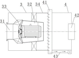
FIG. 2 is a schematic view of the interior of the flue gas scrubbing purifier combined with a cyclonic dehydrator;
fig. 3 is a schematic structural diagram of the activated carbon adsorption tank and the activated carbon adsorption tank cleaning system after combination.
Wherein, the names corresponding to the reference numbers in the drawings are:
1-smoke collecting hood, 2-smoke exhaust pipe, 3-smoke washing purifier, 31-air inlet pipe, 32-air washer, 33-centrifugal impeller, 34-water flow inner side wall area, 4-cyclone dehydrator, 41-annular water discharge ditch, 42-air outlet, 43-axial water discharge channel, 5-electrostatic dust collector, 6-activated carbon adsorption tank, 61-third air pipe, 62-electric heater, 63-electric heating wire, 64-external lead wire, 65-second air pipe, 66-fan, 67-thermometer, 68-first air pipe, 7-air exhaust louver, 8-water return pipe, 9-water supply pipe, 10-water supply pipe, 101-water supply floating ball, 102-water supply electromagnetic valve, 11-circulating water tank, 12-overflow drain pipe, 13-water discharge valve, 14-water pump A, 15-pre-water storage tank, 16-kitchen catering and 17-kitchen drainage ditch.
Detailed Description
The present invention will be described in further detail with reference to examples.
Examples
As shown in fig. 1 to fig. 3, a kitchen catering oil fume purification integrated system comprises a fume collecting hood 1, a fume washing purifier 3, a cyclone dehydrator 4, an electrostatic dust collector 5 and a circulating water tank 11, wherein the fume collecting hood 1 is provided with a fume outlet a, the fume washing purifier 3 is provided with a fume inlet B and a fume outlet B, the fume outlet a of the fume collecting hood 1 is hermetically communicated with the fume inlet B31 of the fume washing purifier 3 through a fume exhaust pipe 2, the fume washing purifier 3 is communicated with the cyclone dehydrator 4, the cyclone dehydrator 4 is communicated with the electrostatic dust collector 5, the electrostatic dust collector 5 is communicated with an exhaust pipe, and an exhaust louver 7 is arranged at the pipe orifice of the exhaust pipe. The bottom of the circulating water tank 11 is communicated with a water feeding pipe 9, a water outlet pipe opening of the water feeding pipe 9 is communicated with a water inlet of the flue gas washing purifier 3 or a smoke discharging end of the smoke discharging pipeline 2 in a sealing mode, a water pump A14 is installed on the water feeding pipe 9, the rotational flow dehydrator 4 is provided with a water discharging opening, and the water discharging opening of the rotational flow dehydrator 4 is communicated with the top of the circulating water tank 11 in a sealing mode through a water returning pipe 8. An overflow drain pipe 12 is arranged inside the circulating water tank 11, a bottom pipe opening of the overflow drain pipe 12 penetrates through the circulating water tank 11 and is arranged outside the circulating water tank 11, a drain pipe is communicated with the bottom of the circulating water tank 11, and a drain valve 13 is arranged on the drain pipe.
As shown in fig. 1, the upper portion of the circulating water tank 11 is connected with a water replenishing floating ball 101 through a swing rod, the upper portion of the circulating water tank 11 is communicated with a water replenishing pipe 10, a water replenishing electromagnetic valve 102 is arranged on the water replenishing pipe 10, the water replenishing electromagnetic valve 102 is a pipeline electromagnetic valve for controlling the on and off of the water replenishing pipe 10, the swing rod of the water replenishing floating ball 101 is hinged to the water replenishing electromagnetic valve 102, one end of the swing rod, which is located inside the water replenishing electromagnetic valve 102, is an energizing switch, the water replenishing electromagnetic valve 102 is internally provided with an energizing contact piece which is electrically connected with the energizing switch of the swing rod, when the water replenishing floating ball 101 descends to a water replenishing position, the water replenishing floating ball 101 drives the energizing switch of the swing rod to contact the energizing contact. When the water replenishing floating ball 101 moves upwards to a position higher than the water replenishing position, the water replenishing floating ball 101 drives the power-on switch of the swing rod to be separated from the power-on contact piece of the water replenishing electromagnetic valve 102, and at the moment, the water replenishing electromagnetic valve 102 is powered off and closed to enable the water replenishing pipe 10 to stop replenishing water into the circulating water tank 11.
As shown in fig. 2, the flue gas washing purifier 3 comprises a flue gas washing cylinder, the cyclone dehydrator 4 comprises a dehydrator cylinder, a gas washing machine 32 is installed in the flue gas washing purifier 3, the gas washing machine 32 has a centrifugal impeller 33, the centrifugal impeller 33 of the gas washing machine 32 corresponds to a smoke inlet B31, one end of the flue gas washing cylinder far away from the smoke inlet B31 is a smoke outlet B, the dehydrator cylinder has an air inlet end a and an air outlet end a, the smoke outlet B of the flue gas washing cylinder is communicated with the air inlet end a of the dehydrator cylinder, the air outlet end a of the dehydrator cylinder has an air outlet 42, and the air outlet 42 of the dehydrator cylinder is communicated with the electrostatic precipitator 5. The flue gas washing barrel is provided with a water flow inner side wall area 34 on one side close to the flue gas outlet B, an annular drainage ditch 41 corresponding to the water flow inner side wall area 34 is installed at one end part of the dehydrator barrel close to the air inlet end A, an axial drainage channel 43 is arranged on the inner side wall of the dehydrator barrel, a water outlet (the water outlet is the water outlet of the cyclone dehydrator 4) is arranged at one end part of the dehydrator barrel close to the air outlet 42, one end part of the axial drainage channel 43 is communicated with the annular drainage ditch 41, and the other end part of the axial drainage channel 43 is communicated with the water. An exhaust fan is disposed in the preferred exhaust port 42 of the present invention.
As shown in fig. 1, an activated carbon adsorption tank 6 is also arranged between the electrostatic dust collector 5 and the exhaust duct. The invention also comprises an activated carbon adsorption tank cleaning system, as shown in fig. 3, the activated carbon adsorption tank cleaning system comprises a fan 66, an electric heater 62 and an external lead 64, the activated carbon adsorption tank 6 is provided with a first end and a second end, an air inlet of the fan 66 is hermetically communicated with the second end of the activated carbon adsorption tank 6 through a first air pipe 68, an air outlet of the fan 66 is hermetically communicated with an air inlet end of the electric heater 62 through a second air pipe 65, and an air outlet end of the electric heater 62 is hermetically communicated with the first end of the activated carbon adsorption tank 6 through a third air pipe 61. An electric heating wire 63 is arranged in the electric heater 62, an external lead 64 penetrates through the electric heater 62 through a lead to be electrically connected with the electric heating wire 63, and an external plug is arranged on the external lead 64. A thermometer 67 is provided outside the first air conduit 68, and a temperature measuring end of the thermometer 67 extends through the first air conduit 68 and is disposed inside the first air conduit 68. The electric heating wire 63 of the present invention is spirally arranged in the electric heater 62 from the air inlet end to the air outlet end.
The level of the top nozzle of the overflow sewage discharge pipe 12 in the circulating water tank 11 is preferably not lower than that of the water replenishing position of the water replenishing floating ball 101.
As shown in fig. 1, a pre-storage water tank 15 is installed in the middle of the upper water pipe 9. A water pump B is also installed on the upper water pipe 4 at the top of the pre-storage water tank 15.
As shown in fig. 2, the annular water drainage trench 41 has an annular water drainage groove, the annular water drainage groove of the annular water drainage trench 41 corresponds to the water flow inner side wall region 34, and the annular water drainage groove of the annular water drainage trench 41 is communicated with the axial water drainage channel 43.
When cooking is carried out, oil smoke and Volatile Organic Compounds (VOCs) generated by kitchen catering kitchen cookers 16 on a cooking bench rise to a smoke collection hood 1, the collected oil smoke enters a smoke washing purifier 3 through a smoke pipeline 2, the oil smoke is washed by washing liquid, then is subjected to gas-liquid separation through a cyclone dehydrator 4, oil stain is discharged into an oil separation tank of a kitchen through a circulating water tank 11 to be subjected to oil recovery, the smoke purification rate reaches 90-95%, the smoke enters an electrostatic dust collector 5 and an active carbon adsorption tank 6 at the rear end, residual pollutants such as the Volatile Organic Compounds (VOCs) and smoke dust in the oil smoke are further purified under the action of a high-voltage electrostatic field and physical adsorption, peculiar smell is eliminated, and the smoke purification rate reaches 98-99% at the moment and is discharged through an exhaust pipe.
The washing liquid (water) enters the water feeding pipe 9 through the bottom of the circulating water tank 11, then the water is pumped into the pre-storage water tank 15 through the water feeding pipe 9 by the water pump A14, and after the pre-storage water tank 15 is full of water, the water enters the inlet nozzle of the air washer 32 through the water feeding pipe 9 extending from the top. The washing liquid (water) combined with the oil smoke flows into the upper part of the circulating water tank 11 from a water outlet at the bottom of the rotational flow dehydrator 4 through a water return pipe 8. When the water level of the circulating water tank 11 drops, the automatic water replenishing valve 10 is opened, and the water in the circulating water tank 11 is replenished to a set water level line. After one cycle of operation, the system needs to be shut down. After the shutdown, the water in the pre-storage water tank 15 automatically flows back to the circulating water tank 11 under the action of natural gravity. The water level of the circulation tank 11 is automatically raised at this time, and when the water level exceeds the overflow drain 12, grease and water flow out of the overflow drain 12 to the kitchen drain 17 because the grease is less dense than water and floats on the water surface.
The above description is only for the purpose of illustrating the preferred embodiments of the present invention and is not to be construed as limiting the invention, and any modifications, equivalents and improvements made within the spirit and principle of the present invention are intended to be included within the scope of the present invention.
Claims (10)
1. The utility model provides a kitchen food and beverage oil smoke purifies integrated system which characterized in that: the device comprises a smoke collecting hood (1), a smoke washing purifier (3), a cyclone dehydrator (4), an electrostatic dust collector (5) and a circulating water tank (11), wherein the smoke collecting hood (1) is provided with a smoke outlet A, the smoke washing purifier (3) is provided with a smoke inlet B and a smoke outlet B, the smoke outlet A of the smoke collecting hood (1) is hermetically communicated with the smoke inlet B (31) of the smoke washing purifier (3) through a smoke exhaust pipeline (2), the smoke washing purifier (3) is communicated with the cyclone dehydrator (4), the cyclone dehydrator (4) is communicated with the electrostatic dust collector (5), the electrostatic dust collector (5) is communicated with an exhaust pipe, and an exhaust louver (7) is arranged at the pipe orifice of the exhaust pipe; the bottom of the circulating water tank (11) is communicated with a water feeding pipe (9), a water outlet pipe opening of the water feeding pipe (9) is communicated with a water inlet of the flue gas washing purifier (3) or a smoke discharging end of the smoke discharging pipeline (2) in a sealing mode, a water pump A (14) is installed on the water feeding pipe (9), the cyclone dehydrator (4) is provided with a water discharging opening, and the water discharging opening of the cyclone dehydrator (4) is communicated with the top of the circulating water tank (11) in a sealing mode through a water returning pipe (8); the inside overflow blow off pipe (12) that is equipped with of circulating water tank (11), the bottom mouth of pipe of overflow blow off pipe (12) runs through circulating water tank (11) and places circulating water tank (11) outside in, circulating water tank (11) bottom intercommunication is equipped with the drain pipe, install drain valve (13) on the drain pipe.
2. The integrated system for purifying cooking oil fume in kitchens as claimed in claim 1, wherein: the upper part of the circulating water tank (11) is connected with a water replenishing floating ball (101) through a swing rod, the upper part of the circulating water tank (11) is communicated with a water replenishing pipe (10), a water replenishing electromagnetic valve (102) is arranged on the water replenishing pipe (10), the water replenishing electromagnetic valve (102) is a pipeline electromagnetic valve for controlling the on-off of the water replenishing pipe (10), a swing rod of the water replenishing floating ball (101) is hinged with a water replenishing electromagnetic valve (102), one end of the swing rod, which is positioned in the water replenishing electromagnetic valve (102), is an electrified switch, the water replenishing electromagnetic valve (102) is internally provided with an electrified contact piece which is electrically connected with an electrified switch of the swing rod, when the water replenishing floating ball (101) descends to a water replenishing position, the water replenishing floating ball (101) drives an electrified switch of the swing rod to contact an electrified contact piece of the water replenishing electromagnetic valve (102), and the water replenishing electromagnetic valve (102) is electrified and opened at the moment so that the water replenishing pipe (10) replenishes water into the circulating water tank (11); when the water replenishing floating ball (101) moves upwards to a position higher than the water replenishing position, the water replenishing floating ball (101) drives the power-on switch of the swing rod to be separated from the power-on contact piece of the water replenishing electromagnetic valve (102), and the water replenishing electromagnetic valve (102) is powered off and closed to enable the water replenishing pipe (10) to stop replenishing water into the circulating water tank (11).
3. The integrated system for purifying cooking oil fume in kitchens as claimed in claim 1 or 2, wherein: the flue gas washing purifier (3) comprises a flue gas washing cylinder, the cyclone dehydrator (4) comprises a dehydrator cylinder, a gas washing machine (32) is installed in the flue gas washing purifier (3), the gas washing machine (32) is provided with a centrifugal impeller (33), the centrifugal impeller (33) of the gas washing machine (32) corresponds to the smoke inlet B (31), one end of the flue gas washing cylinder, which is far away from the smoke inlet B (31), is a smoke outlet B, the dehydrator cylinder is provided with a gas inlet end A and a gas outlet end A, the smoke outlet B of the flue gas washing cylinder is communicated with the gas inlet end A of the dehydrator cylinder, the gas outlet end A of the dehydrator cylinder is provided with a gas outlet (42), and the gas outlet (42) of the dehydrator cylinder is communicated with the electrostatic dust collector (5); the flue gas washing barrel is close to outlet flue B one side and has rivers inside wall region (34), the dehydrator barrel is close to the one end tip of inlet end A and installs the cyclic annular drainage ditch (41) corresponding with rivers inside wall region (34), be equipped with axial drainage channel (43) on the dehydrator barrel inside wall, the dehydrator barrel is close to the one end tip of air exit (42) and is equipped with the outlet, axial drainage channel (43) one end tip is linked together with cyclic annular drainage ditch (41), axial drainage channel (43) other end tip and the airtight intercommunication of outlet.
4. The integrated system for purifying cooking oil fume in kitchens as claimed in claim 1 or 2, wherein: and an activated carbon adsorption box (6) is communicated between the electrostatic dust collector (5) and the exhaust pipe.
5. The integrated system for purifying cooking oil fume in kitchens as claimed in claim 4, wherein: the cleaning system comprises a fan (66), an electric heater (62) and an external lead (64), the activated carbon adsorption tank (6) is provided with a first end and a second end, an air inlet of the fan (66) is communicated with the second end of the activated carbon adsorption tank (6) in a sealing mode through a first air pipe (68), an air outlet of the fan (66) is communicated with an air inlet end of the electric heater (62) in a sealing mode through a second air pipe (65), and an air outlet end of the electric heater (62) is communicated with the first end of the activated carbon adsorption tank (6) in a sealing mode through a third air pipe (61); an electric heating wire (63) is arranged in the electric heater (62), an external lead (64) penetrates through the electric heater (62) through a lead to be electrically connected with the electric heating wire (63), and an external plug is arranged on the external lead (64); a thermometer (67) is arranged outside the first air pipe (68), and the temperature measuring end of the thermometer (67) penetrates through the first air pipe (68) and is arranged inside the first air pipe (68).
6. The integrated system for purifying cooking oil fume in kitchens as claimed in claim 2, wherein: the level height of a top pipe orifice of the overflow sewage discharge pipe (12) in the circulating water tank (11) is not lower than the level height of a water supplementing position of the water supplementing floating ball (101).
7. The integrated system for purifying cooking oil fume in kitchens as claimed in claim 1, wherein: the middle part of the upper water pipe (9) is communicated with a pre-storage water tank (15); a water pump B is also arranged on the upper water pipe (4) positioned at the top of the pre-storage water tank (15).
8. The integrated system for purifying cooking oil fume in kitchens as claimed in claim 3, wherein: the annular drainage trench (41) is provided with an annular drainage groove, the annular drainage groove of the annular drainage trench (41) corresponds to the water flow inner side wall area (34), and the annular drainage groove of the annular drainage trench (41) is communicated with the axial drainage channel (43).
9. The integrated system for purifying cooking oil fume in kitchens as claimed in claim 3 or 8, wherein: an exhaust fan is arranged in the exhaust outlet (42).
10. The integrated system for purifying cooking oil fume in kitchens as claimed in claim 5, wherein: the electric heating wires (63) are sequentially and spirally arranged from the air inlet end to the air outlet end in the electric heater (62).
Priority Applications (1)
| Application Number | Priority Date | Filing Date | Title |
|---|---|---|---|
| CN201811413614.7A CN111219755A (en) | 2018-11-26 | 2018-11-26 | Kitchen catering oil smoke purifies integrated system |
Applications Claiming Priority (1)
| Application Number | Priority Date | Filing Date | Title |
|---|---|---|---|
| CN201811413614.7A CN111219755A (en) | 2018-11-26 | 2018-11-26 | Kitchen catering oil smoke purifies integrated system |
Publications (1)
| Publication Number | Publication Date |
|---|---|
| CN111219755A true CN111219755A (en) | 2020-06-02 |
Family
ID=70810000
Family Applications (1)
| Application Number | Title | Priority Date | Filing Date |
|---|---|---|---|
| CN201811413614.7A Pending CN111219755A (en) | 2018-11-26 | 2018-11-26 | Kitchen catering oil smoke purifies integrated system |
Country Status (1)
| Country | Link |
|---|---|
| CN (1) | CN111219755A (en) |
Cited By (2)
| Publication number | Priority date | Publication date | Assignee | Title |
|---|---|---|---|---|
| CN113019077A (en) * | 2021-03-16 | 2021-06-25 | 山东驰盛新能源设备有限公司 | Low-nitrogen low-sulfur coke oven VOC treatment system |
| CN114733310A (en) * | 2022-04-14 | 2022-07-12 | 深圳市太豪七餐饮管理有限公司 | Catering oil fume purification device |
Citations (6)
| Publication number | Priority date | Publication date | Assignee | Title |
|---|---|---|---|---|
| WO2011074250A1 (en) * | 2009-12-16 | 2011-06-23 | パナソニック株式会社 | Oily smoke purifying device |
| CN103438490A (en) * | 2013-09-17 | 2013-12-11 | 天津曌宇环保科技发展有限公司 | Lampblack purifying machine for kitchen |
| CN105526609A (en) * | 2014-09-29 | 2016-04-27 | 琳鸿轩(北京)工贸有限公司 | Fume exhaust hood used for purifying catering oil fume |
| CN205886490U (en) * | 2016-07-25 | 2017-01-18 | 崔启 | Combined type food and beverage oil smoke clean system |
| CN206837803U (en) * | 2017-06-14 | 2018-01-05 | 北京基伊节能环保科技有限公司 | Composite oil smoke cleaning system |
| CN210107495U (en) * | 2018-11-26 | 2020-02-21 | 辽宁基伊环保科技股份有限公司 | Kitchen catering oil smoke purifies integrated system |
-
2018
- 2018-11-26 CN CN201811413614.7A patent/CN111219755A/en active Pending
Patent Citations (6)
| Publication number | Priority date | Publication date | Assignee | Title |
|---|---|---|---|---|
| WO2011074250A1 (en) * | 2009-12-16 | 2011-06-23 | パナソニック株式会社 | Oily smoke purifying device |
| CN103438490A (en) * | 2013-09-17 | 2013-12-11 | 天津曌宇环保科技发展有限公司 | Lampblack purifying machine for kitchen |
| CN105526609A (en) * | 2014-09-29 | 2016-04-27 | 琳鸿轩(北京)工贸有限公司 | Fume exhaust hood used for purifying catering oil fume |
| CN205886490U (en) * | 2016-07-25 | 2017-01-18 | 崔启 | Combined type food and beverage oil smoke clean system |
| CN206837803U (en) * | 2017-06-14 | 2018-01-05 | 北京基伊节能环保科技有限公司 | Composite oil smoke cleaning system |
| CN210107495U (en) * | 2018-11-26 | 2020-02-21 | 辽宁基伊环保科技股份有限公司 | Kitchen catering oil smoke purifies integrated system |
Cited By (2)
| Publication number | Priority date | Publication date | Assignee | Title |
|---|---|---|---|---|
| CN113019077A (en) * | 2021-03-16 | 2021-06-25 | 山东驰盛新能源设备有限公司 | Low-nitrogen low-sulfur coke oven VOC treatment system |
| CN114733310A (en) * | 2022-04-14 | 2022-07-12 | 深圳市太豪七餐饮管理有限公司 | Catering oil fume purification device |
Similar Documents
| Publication | Publication Date | Title |
|---|---|---|
| CN103644588A (en) | Self-cleaning smoke exhaust ventilator | |
| CN210107495U (en) | Kitchen catering oil smoke purifies integrated system | |
| CN202494157U (en) | Integral oil-fume purifying machine | |
| CN111219755A (en) | Kitchen catering oil smoke purifies integrated system | |
| CN2340492Y (en) | Deodorizing and oily smoke purifier | |
| CN107676836A (en) | A kind of lampblack absorber Intelligent purifying cleaning device | |
| CN201539913U (en) | Flue gas cleaner of smoke exhaust ventilator | |
| CN103791535B (en) | A kind of speed change Whirlwind cooking fume purifier | |
| CN103528106B (en) | A kind of smoke exhaust ventilator and method with gas cleaning and oil recovery function | |
| CN2858037Y (en) | Table type fume purifying machine | |
| CN202709243U (en) | Novel oil-smoke purification all-in-one machine | |
| CN201779737U (en) | Front end wet-type oil fume purifier in food industry | |
| CN103672996B (en) | A kind of method purifying kitchen fume and internal discharging type environment-protecting kitchen ventilator | |
| CN109999598B (en) | Embedded chimney flue gas dust removal fume extractor | |
| CN209512142U (en) | A kind of rectangular smoke purifier | |
| CN203757808U (en) | Variable speed cyclone oil smoke purifier | |
| CN205156079U (en) | Integrated kitchen | |
| CN203771497U (en) | Self-cleaning smoke exhauster | |
| CN202082996U (en) | Range hood for oil fume decontamination of household kitchens | |
| CN203517948U (en) | Smoke exhaust ventilator with smoke gas purification and grease recovery function | |
| CN203043778U (en) | Dust and exhaust gas treatment system in workshop | |
| CN101706121A (en) | Oil fume purification device of oil fume exhauster | |
| CN205287890U (en) | Kitchen air clarifier | |
| CN201916971U (en) | Embedded type integrated range hood with device for separating water fogs and oil fume and preventing fire | |
| CN201652562U (en) | Oil-gas separation exhaust machine |
Legal Events
| Date | Code | Title | Description |
|---|---|---|---|
| PB01 | Publication | ||
| PB01 | Publication | ||
| TA01 | Transfer of patent application right |
Effective date of registration: 20200520 Address after: 110000 North Station Road, Shenhe District, Shenyang, Liaoning Province, No. 146 Applicant after: LIAONING JET ENGINEERING ENERGY TECHNOLOGY Co.,Ltd. Address before: The innovation road of Shenyang city Liaoning province 110000 Hunnan District No. 155-5 Applicant before: LIAONING JIYI ENVIRONMENTAL SCIENCE AND TECHNOLOGY Co.,Ltd. |
|
| TA01 | Transfer of patent application right | ||
| SE01 | Entry into force of request for substantive examination | ||
| SE01 | Entry into force of request for substantive examination |