CN111207116A - Scavenger fan with air filtering structure - Google Patents
Scavenger fan with air filtering structure Download PDFInfo
- Publication number
- CN111207116A CN111207116A CN201811395430.2A CN201811395430A CN111207116A CN 111207116 A CN111207116 A CN 111207116A CN 201811395430 A CN201811395430 A CN 201811395430A CN 111207116 A CN111207116 A CN 111207116A
- Authority
- CN
- China
- Prior art keywords
- filter
- filtering
- air
- ventilator
- holes
- Prior art date
- Legal status (The legal status is an assumption and is not a legal conclusion. Google has not performed a legal analysis and makes no representation as to the accuracy of the status listed.)
- Withdrawn
Links
Images


Classifications
-
- F—MECHANICAL ENGINEERING; LIGHTING; HEATING; WEAPONS; BLASTING
- F04—POSITIVE - DISPLACEMENT MACHINES FOR LIQUIDS; PUMPS FOR LIQUIDS OR ELASTIC FLUIDS
- F04D—NON-POSITIVE-DISPLACEMENT PUMPS
- F04D29/00—Details, component parts, or accessories
- F04D29/70—Suction grids; Strainers; Dust separation; Cleaning
- F04D29/701—Suction grids; Strainers; Dust separation; Cleaning especially adapted for elastic fluid pumps
- F04D29/703—Suction grids; Strainers; Dust separation; Cleaning especially adapted for elastic fluid pumps specially for fans, e.g. fan guards
-
- F—MECHANICAL ENGINEERING; LIGHTING; HEATING; WEAPONS; BLASTING
- F04—POSITIVE - DISPLACEMENT MACHINES FOR LIQUIDS; PUMPS FOR LIQUIDS OR ELASTIC FLUIDS
- F04D—NON-POSITIVE-DISPLACEMENT PUMPS
- F04D29/00—Details, component parts, or accessories
- F04D29/002—Details, component parts, or accessories especially adapted for elastic fluid pumps
-
- F—MECHANICAL ENGINEERING; LIGHTING; HEATING; WEAPONS; BLASTING
- F04—POSITIVE - DISPLACEMENT MACHINES FOR LIQUIDS; PUMPS FOR LIQUIDS OR ELASTIC FLUIDS
- F04D—NON-POSITIVE-DISPLACEMENT PUMPS
- F04D29/00—Details, component parts, or accessories
- F04D29/40—Casings; Connections of working fluid
- F04D29/403—Casings; Connections of working fluid especially adapted for elastic fluid pumps
Abstract
The invention discloses a ventilator with an air filtering structure, which comprises a shell, a collecting tank and a second filtering mechanism, wherein a vent is arranged inside the side surface of the shell, a shutter is connected inside the vent, the back surface of the shell is connected with a back plate, an inner cavity is fixed inside the shell, a first filtering mechanism is arranged inside the inner cavity, a purifying mechanism is arranged on the back surface of the first filtering mechanism, and the collecting tank is arranged on the bottom end surface of the inner cavity. According to the invention, through the arrangement of the diameters of the inner meshes between the first filter plate and the second filter plate, impurities with different diameters can be filtered in the air sucked by the ventilator, so that the influence on the flowing direction of the air in the purifying mechanism and the purification efficiency of the purifying mechanism due to the blockage of the purifying mechanism caused by larger impurity particles is avoided, and convenience is provided for the purification work of the purifying equipment due to the arrangement of the filter plates.
Description
Technical Field
The invention relates to the technical field of ventilation in high and new industries, in particular to a ventilation fan with an air filtering structure.
Background
The ventilating fan drives the fan blades to rotate by the motor to drive airflow, so that the application field of the air conditioning electric appliance, also called as a ventilating fan, for exchanging indoor air and outdoor air is continuously expanded along with the continuous development of science and technology, thereby innovating and designing the ventilating fan for high and new industries and promoting the development of the high and new industries.
The existing ventilation fan for ventilation in high and new industries cannot filter and purify impurities mixed in sucked air during ventilation, so that impurity particles in the air are large, related parts in the ventilation fan are affected to a certain degree, and the sucked air cannot be purified, so that the gas pollutes the outside air.
Disclosure of Invention
The present invention provides a ventilator with an air filtering structure, so as to solve the problems that the conventional ventilator for ventilation in the high and new industries proposed in the background art cannot filter and purify impurities mixed in the sucked air during ventilation, so that the impurity particles in the air are large, the related components in the ventilator are affected to a certain extent, and the sucked air cannot be purified, so that the air pollutes the outside air.
In order to achieve the purpose, the invention provides the following technical scheme: the utility model provides a scavenger fan with filtration structure, includes casing, collecting vat and second filtering mechanism, the inside vent that is provided with in side of casing, and the internal connection of vent has the shutter, the back connection of casing has the back plate, and the inside of casing is fixed with the inner chamber, the inside of inner chamber is provided with first filtering mechanism, and the back of first filtering mechanism is provided with and purifies the mechanism, the collecting vat sets up in the bottom surface of inner chamber, and the bottom of collecting vat is connected with flexible pipe, the bottom of flexible pipe is connected with the collecting box, the second filtering mechanism be fixed in the positive inside of casing, and inner wall one side of second filtering mechanism is provided with the fan.
Preferably, the inside of first filter mechanism is including first filter and second filter, the back of first filter is provided with the second filter.
Preferably, the diameters of the meshes in the first filter plate and the second filter plate are different, and the diameters of the first filter plate and the second filter plate are larger than that of the fan.
Preferably, the inside of purifying mechanism is including through-hole, catalyst strip, connecting hole, recess and lug, the inside of through-hole is provided with the catalyst strip, and the outer wall surface of catalyst strip is provided with the lug, the inner wall surface of through-hole is provided with the recess, and is provided with the connecting hole between the through-hole.
Preferably, the through holes are communicated with each other through connecting holes, the inside of the purification mechanism forms a honeycomb structure through the through holes, and the catalyst strips form a detachable structure through the matching of the grooves and the bumps and the through holes.
Preferably, the inside of the second filtering mechanism comprises a first filtering mesh and a second filtering mesh, and the back of the first filtering mesh is connected with the second filtering mesh.
Preferably, the first filter mesh and the second filter mesh are symmetrical about a vertical center line of the second filter mechanism, and the diameter of the first filter mesh is reduced from outside to inside.
Compared with the prior art, the invention has the following beneficial effects:
1. according to the invention, through the arrangement of the diameters of the inner meshes between the first filter plate and the second filter plate, impurities with different diameters can be filtered in the air sucked by the ventilator, so that the phenomenon that the impurities block the interior of the purification mechanism due to larger particles, the influence on the flowing direction of the air in the purification mechanism is further caused, and the influence on the purification efficiency is further caused is avoided, and therefore, the arrangement of the filter plates can provide convenience for the purification work of the purification equipment;
2. the invention is characterized in that the through holes are distributed in the purifying mechanism at equal intervals and uniformly, the number of the through holes is arranged to ensure that the purifying mechanism is in a honeycomb structure, the through holes form a through structure through the connecting holes, the through structure is mutually matched with the honeycomb structure in the purifying mechanism, so that the purifying mechanism can change the flow direction of the gas in the purifying mechanism, the retention time of the gas in the purifying mechanism is prolonged, the gas can be fully contacted with the catalyst strip, the catalyst strip can adsorb and deodorize fine impurities in the air through catalytic articles filled in the catalyst strip, such as active carbon, bamboo charcoal and other materials, thereby improving the service performance of the ventilator, and the assembling and disassembling work between the catalyst strip and the through holes are facilitated through the combination of the grooves and the lugs, the replacement of the spent catalyst strip is facilitated, so that the requirement of the ventilation fan on an air filtering structure is met through the mutual matching of the components;
3. the diameter of the first filter mesh is set to be larger outside and smaller inside, and the size of the second filter mesh effectively accelerates the flow speed of air at the inner opening of the ventilator, so that the second filter mechanism can filter the sucked air and simultaneously reduce the influence on the flow speed rate of the air at the inner opening of the ventilator due to the diameter of the inner mesh by the mutual matching of the first filter mesh and the second filter mesh, and the inside of the ventilator can be protected from dust to a certain extent when the ventilator is idle by the diameter of the first filter mesh, so that the influence on the use performance of internal parts due to more dust accumulation in the ventilator is avoided.
Drawings
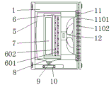
FIG. 1 is a side view of the internal structure of the present invention;
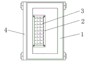
FIG. 2 is a side view of the external structure of the present invention;
FIG. 3 is a schematic view of the front view of the internal structure of the purification mechanism of the present invention;
FIG. 4 is an enlarged schematic view of the structure at A of the present invention.
In the figure: 1. a housing; 2. a vent; 3. a blind window; 4. a back plate; 5. an inner cavity; 6. a first filter mechanism; 601. a first filter plate; 602. a second filter plate; 7. a purification mechanism; 701. a through hole; 702. a catalyst strip; 703. connecting holes; 704. a groove; 705. a bump; 8. collecting tank; 9. a telescopic pipe; 10. a collection box; 11. a second filter mechanism; 1101. a first filter mesh; 1102. a second filter mesh; 12. a fan.
Detailed Description
The technical solutions in the embodiments of the present invention will be clearly and completely described below with reference to the drawings in the embodiments of the present invention, and it is obvious that the described embodiments are only a part of the embodiments of the present invention, and not all of the embodiments. All other embodiments, which can be derived by a person skilled in the art from the embodiments given herein without making any creative effort, shall fall within the protection scope of the present invention.
Referring to fig. 1-4, the present invention provides a technical solution: a ventilator with an air filtering structure comprises a shell 1, a collecting tank 8 and a second filtering mechanism 11, wherein a vent 2 is arranged inside the side surface of the shell 1, a louver 3 is connected inside the vent 2, a back plate 4 is connected to the back surface of the shell 1, an inner cavity 5 is fixed inside the shell 1, a first filtering mechanism 6 is arranged inside the inner cavity 5, a purifying mechanism 7 is arranged on the back surface of the first filtering mechanism 6, a first filtering plate 601 and a second filtering plate 602 are arranged inside the first filtering mechanism 6, a second filtering plate 602 is arranged on the back surface of the first filtering plate 601, the diameters of meshes inside the first filtering plate 601 and the second filtering plate 602 are different, the diameters of the first filtering plate 601 and the second filtering plate 602 are larger than that of a fan 12, and the diameters of meshes inside the first filtering plate 601 and the second filtering plate 602 are set so that impurities with different diameters can be filtered in the air sucked by the ventilator, therefore, the phenomenon that the impurity particles are larger to block the inside of the purifying mechanism 7, so that the flowing direction of air in the purifying mechanism is influenced and the purifying efficiency of the purifying mechanism is influenced is avoided, and convenience is brought to the purifying work of purifying equipment due to the arrangement of the filter plate;
the inside of the purification mechanism 7 comprises a through hole 701, a catalyst strip 702, a connecting hole 703, a groove 704 and a bump 705, the catalyst strip 702 is arranged inside the through hole 701, the bump 705 is arranged on the outer wall surface of the catalyst strip 702, the groove 704 is arranged on the inner wall surface of the through hole 701, the connecting holes 703 are arranged between the through holes 701, the through holes 701 are communicated with each other through the connecting hole 703, the inside of the purification mechanism 7 forms a honeycomb structure through the through hole 701, the catalyst strip 702 forms a detachable structure through the matching of the groove 704 and the bump 705 and the through hole 701, the through holes 701 are equidistantly and uniformly distributed inside the purification mechanism 7, the arrangement of the number of the through holes makes the inside of the purification mechanism 7 form a honeycomb structure, the through holes 701 form a through structure through the connecting hole 703, the through structure is mutually matched with the honeycomb structure inside the purification mechanism 7, so that the purification mechanism 7 can, the stay time of the gas in the ventilator is prolonged, so that the gas can be fully contacted with the catalyst strips 702, the catalyst strips 702 can adsorb and deodorize fine impurities in the air through catalytic articles filled in the ventilator, such as activated carbon, bamboo charcoal and other materials, so that the use performance of the ventilator is improved, the disassembly and assembly between the catalyst strips 702 and the through holes 701 can be facilitated through the combination of the grooves 704 and the bumps 705, and the replacement of the failed catalyst strips 702 is facilitated, so that the requirements of the ventilator on an air filtering structure are met through the mutual matching of the components;
the collecting tank 8 is arranged on the bottom end surface of the inner cavity 5, the bottom end of the collecting tank 8 is connected with an extension pipe 9, the bottom end of the extension pipe 9 is connected with a collecting tank 10, the second filtering mechanism 11 is fixed in the front inside of the shell 1, one side of the inner wall of the second filtering mechanism 11 is provided with a fan 12, the inside of the second filtering mechanism 11 comprises a first filtering mesh 1101 and a second filtering mesh 1102, the back side of the first filtering mesh 1101 is connected with the second filtering mesh 1102, the first filtering mesh 1101 and the second filtering mesh 1102 are symmetrical about the vertical central line of the second filtering mechanism 11, the diameter of the first filtering mesh 1101 is sequentially reduced from outside to inside, the diameter of the first filtering mesh 1101 is set so that the first filtering mesh 1101 can filter impurities with larger particles in the sucked air to a certain degree, the diameter of the second filtering mesh 1102 is set to be larger outside and smaller inside, and the size of the ventilator effectively accelerates the flow speed of the internal air, the event is through mutual cooperation between first filtration mesh 1101 and the second filtration mesh 1102 for second filter mechanism 11 can be when filtering the inhaled air, has also reduced because the influence that the speed rate that the setting of inside mesh diameter caused its inside air flow, and through the setting of first filtration mesh 1101 diameter, can carry out certain degree dustproof protection to the scavenger fan inside when idle, thereby has avoided because its inside dust gathering is more, the influence that causes the performance of its inside part.
The working principle is as follows: for the ventilation fan with the air filtering structure, when in use, firstly, the rotation of the fan 12 enables the pressure inside the ventilation fan to be smaller than the pressure outside the equipment, so that the external air can be sucked into the ventilation fan, the impurities mixed in the sucked air can be primarily filtered through the first filtering meshes 1101 inside the second filtering mechanism 11, and the flowing speed of the primarily filtered air can be accelerated through the second filtering meshes 1102, so that the influence of the diameter of the inner meshes on the flowing speed of the air inside the ventilation fan due to the arrangement of the diameter of the inner meshes is reduced when the second filtering mechanism 11 filters the sucked air through the mutual matching of the first filtering plate 601 and the second filtering plate 602, and then, the impurities with different diameters, mixed in the sucked air, can be fully filtered through the mutual matching of the first filtering plate 601 and the second filtering plate 602, therefore, the problem that the impurity particles in the air have larger diameters to block the inside of the purification mechanism 7, so that the purification efficiency of the purification mechanism is influenced is avoided;
secondly, the direction of the air flowing in the purifying mechanism 7 can be changed by the mutual matching between the through hole 701 and the connecting hole 703 in the purifying mechanism 7, so that the time of the gas staying in the purifying mechanism 7 is prolonged, the gas can be fully contacted with the catalyst strip 702, the catalyst strip 702 can adsorb and deodorize fine impurities in the air through catalytic articles filled in the catalyst strip 702, such as activated carbon, bamboo charcoal and other materials, thereby improving the service performance of the ventilator, and the disassembly and assembly between the catalyst strip 702 and the through hole 701 can be facilitated by the combination between the groove 704 and the bump 705, thereby facilitating the replacement of the failed catalyst strip 702, finally the purified gas can be discharged to the outside of the device through the vent 2, and the solid or fluid substances filtered between the inner cavity 5 and the first filter plate 601 and the second filter plate 602 can be subjected to the collection tank 8 The impurities are collected and can be transmitted to the inside of the collecting box 10 through the telescopic pipe 9, and then the collecting box 10 needs to be cleaned regularly, so that the using process of the ventilating fan with the air filtering structure is completed.
Although embodiments of the present invention have been shown and described, it will be appreciated by those skilled in the art that changes, modifications, substitutions and alterations can be made in these embodiments without departing from the principles and spirit of the invention, the scope of which is defined in the appended claims and their equivalents.
Claims (7)
1. The utility model provides a scavenger fan with air filtering structure, includes casing (1), collecting vat (8) and second filter mechanism (11), its characterized in that: the side of casing (1) is inside to be provided with vent (2), and the internal connection of vent (2) has shutter (3), the back connection of casing (1) has back plate (4), and the inside of casing (1) is fixed with inner chamber (5), the inside of inner chamber (5) is provided with first filter mechanism (6), and the back of first filter mechanism (6) is provided with purification mechanism (7), collecting vat (8) set up in the bottom surface of inner chamber (5), and the bottom of collecting vat (8) is connected with flexible pipe (9), the bottom of flexible pipe (9) is connected with collecting box (10), the front inside of casing (1) is fixed in of second filter mechanism (11), and inner wall one side of second filter mechanism (11) is provided with fan (12).
2. The ventilator with an air filtering structure according to claim 1, wherein: the inside of first filter mechanism (6) is including first filter (601) and second filter (602), the back of first filter (601) is provided with second filter (602).
3. The ventilator with an air filtering structure according to claim 2, wherein: the inside mesh diameter between first filter (601) and second filter (602) is different, and the diameter of first filter (601), second filter (602) is greater than the diameter of fan (12).
4. The ventilator with an air filtering structure according to claim 1, wherein: the purification mechanism (7) is characterized in that the purification mechanism (7) comprises a through hole (701), a catalyst strip (702), a connecting hole (703), a groove (704) and a bump (705), the catalyst strip (702) is arranged in the through hole (701), the bump (705) is arranged on the outer wall surface of the catalyst strip (702), the groove (704) is arranged on the inner wall surface of the through hole (701), and the connecting hole (703) is formed between the through holes (701).
5. The ventilator with an air filtering structure according to claim 4, wherein: the through holes (701) are communicated with each other through connecting holes (703), the inside of the purification mechanism (7) forms a honeycomb structure through the through holes (701), and the catalyst strips (702) form a detachable structure through the matching of the grooves (704) and the bumps (705) and the through holes (701).
6. The ventilator with an air filtering structure according to claim 1, wherein: the inside of the second filtering mechanism (11) comprises a first filtering mesh (1101) and a second filtering mesh (1102), and the back of the first filtering mesh (1101) is connected with the second filtering mesh (1102).
7. The ventilator with an air filtering structure according to claim 6, wherein: the first filtering mesh holes (1101) and the second filtering mesh holes (1102) are symmetrical about a vertical central line of the second filtering mechanism (11), and the diameters of the first filtering mesh holes (1101) are reduced from outside to inside.
Priority Applications (1)
| Application Number | Priority Date | Filing Date | Title |
|---|---|---|---|
| CN201811395430.2A CN111207116A (en) | 2018-11-22 | 2018-11-22 | Scavenger fan with air filtering structure |
Applications Claiming Priority (1)
| Application Number | Priority Date | Filing Date | Title |
|---|---|---|---|
| CN201811395430.2A CN111207116A (en) | 2018-11-22 | 2018-11-22 | Scavenger fan with air filtering structure |
Publications (1)
| Publication Number | Publication Date |
|---|---|
| CN111207116A true CN111207116A (en) | 2020-05-29 |
Family
ID=70788170
Family Applications (1)
| Application Number | Title | Priority Date | Filing Date |
|---|---|---|---|
| CN201811395430.2A Withdrawn CN111207116A (en) | 2018-11-22 | 2018-11-22 | Scavenger fan with air filtering structure |
Country Status (1)
| Country | Link |
|---|---|
| CN (1) | CN111207116A (en) |
Cited By (1)
| Publication number | Priority date | Publication date | Assignee | Title |
|---|---|---|---|---|
| CN112208945A (en) * | 2020-09-27 | 2021-01-12 | 中国人民解放军陆军军医大学第二附属医院 | Air exchange blood supply box |
-
2018
- 2018-11-22 CN CN201811395430.2A patent/CN111207116A/en not_active Withdrawn
Cited By (1)
| Publication number | Priority date | Publication date | Assignee | Title |
|---|---|---|---|---|
| CN112208945A (en) * | 2020-09-27 | 2021-01-12 | 中国人民解放军陆军军医大学第二附属医院 | Air exchange blood supply box |
Similar Documents
| Publication | Publication Date | Title |
|---|---|---|
| CN203809322U (en) | Household electric fan with air purification function | |
| WO2021057226A1 (en) | Air purifier | |
| CN111207116A (en) | Scavenger fan with air filtering structure | |
| CN209828529U (en) | Dust removal device for draught fan | |
| CN210964482U (en) | Defogging device with gaseous purification performance | |
| CN220648467U (en) | Filter screen assembly for central air conditioner | |
| CN209053843U (en) | A kind of ventilation fan with air filtration structure | |
| CN216977080U (en) | Warm logical air conditioner filter equipment that leads to for engineering | |
| CN216132046U (en) | Air purification module for heating and ventilating pipeline | |
| CN110864341A (en) | Kitchen oil smoke exhaust-gas treatment equipment | |
| CN220689262U (en) | Fresh air system | |
| CN217057807U (en) | Novel dedicated multiple layer formula air-purifying air supply of clean operating room device | |
| CN215428027U (en) | Airflow filtering system for spraying chamber | |
| CN214075545U (en) | Sack filter is used in magnesium chloride production | |
| CN216694528U (en) | Warm cooling tower that leads to | |
| CN215490197U (en) | Air purification device for hot melt adhesive processing workshop | |
| CN216630094U (en) | Low-resistance efficient air filter | |
| CN207493405U (en) | Environmental protection and energy saving activated-charcoal purifier | |
| CN214701207U (en) | Active noise reduction device for laminar flow air port | |
| CN220366495U (en) | Central air conditioning wind gap degassing unit | |
| CN211245799U (en) | Novel engineering dust exhausting fan | |
| CN220003298U (en) | Purifier convenient to filter core is changed in dismouting | |
| CN213527982U (en) | Self-cleaning dust-removing air purification device | |
| CN212777798U (en) | Dehumidification electrolysis air-purifying device | |
| CN210448498U (en) | Self-cleaning shaftless spiral flue for mixed gas transmission |
Legal Events
| Date | Code | Title | Description |
|---|---|---|---|
| PB01 | Publication | ||
| PB01 | Publication | ||
| SE01 | Entry into force of request for substantive examination | ||
| SE01 | Entry into force of request for substantive examination | ||
| WW01 | Invention patent application withdrawn after publication | ||
| WW01 | Invention patent application withdrawn after publication |
Application publication date: 20200529 |