CN111203803A - Aluminium alloy processingequipment that polishes - Google Patents
Aluminium alloy processingequipment that polishes Download PDFInfo
- Publication number
- CN111203803A CN111203803A CN202010110415.XA CN202010110415A CN111203803A CN 111203803 A CN111203803 A CN 111203803A CN 202010110415 A CN202010110415 A CN 202010110415A CN 111203803 A CN111203803 A CN 111203803A
- Authority
- CN
- China
- Prior art keywords
- aluminum profile
- plate
- side wall
- inverted
- processing device
- Prior art date
- Legal status (The legal status is an assumption and is not a legal conclusion. Google has not performed a legal analysis and makes no representation as to the accuracy of the status listed.)
- Withdrawn
Links
Images


Classifications
-
- B—PERFORMING OPERATIONS; TRANSPORTING
- B24—GRINDING; POLISHING
- B24B—MACHINES, DEVICES, OR PROCESSES FOR GRINDING OR POLISHING; DRESSING OR CONDITIONING OF ABRADING SURFACES; FEEDING OF GRINDING, POLISHING, OR LAPPING AGENTS
- B24B41/00—Component parts such as frames, beds, carriages, headstocks
- B24B41/06—Work supports, e.g. adjustable steadies
- B24B41/067—Work supports, e.g. adjustable steadies radially supporting workpieces
-
- B—PERFORMING OPERATIONS; TRANSPORTING
- B24—GRINDING; POLISHING
- B24B—MACHINES, DEVICES, OR PROCESSES FOR GRINDING OR POLISHING; DRESSING OR CONDITIONING OF ABRADING SURFACES; FEEDING OF GRINDING, POLISHING, OR LAPPING AGENTS
- B24B27/00—Other grinding machines or devices
- B24B27/0015—Hanging grinding machines
-
- B—PERFORMING OPERATIONS; TRANSPORTING
- B24—GRINDING; POLISHING
- B24B—MACHINES, DEVICES, OR PROCESSES FOR GRINDING OR POLISHING; DRESSING OR CONDITIONING OF ABRADING SURFACES; FEEDING OF GRINDING, POLISHING, OR LAPPING AGENTS
- B24B5/00—Machines or devices designed for grinding surfaces of revolution on work, including those which also grind adjacent plane surfaces; Accessories therefor
- B24B5/02—Machines or devices designed for grinding surfaces of revolution on work, including those which also grind adjacent plane surfaces; Accessories therefor involving centres or chucks for holding work
- B24B5/04—Machines or devices designed for grinding surfaces of revolution on work, including those which also grind adjacent plane surfaces; Accessories therefor involving centres or chucks for holding work for grinding cylindrical surfaces externally
- B24B5/045—Machines or devices designed for grinding surfaces of revolution on work, including those which also grind adjacent plane surfaces; Accessories therefor involving centres or chucks for holding work for grinding cylindrical surfaces externally with the grinding wheel axis perpendicular to the workpiece axis
-
- B—PERFORMING OPERATIONS; TRANSPORTING
- B24—GRINDING; POLISHING
- B24B—MACHINES, DEVICES, OR PROCESSES FOR GRINDING OR POLISHING; DRESSING OR CONDITIONING OF ABRADING SURFACES; FEEDING OF GRINDING, POLISHING, OR LAPPING AGENTS
- B24B5/00—Machines or devices designed for grinding surfaces of revolution on work, including those which also grind adjacent plane surfaces; Accessories therefor
- B24B5/35—Accessories
Abstract
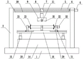
The invention discloses an aluminum profile polishing device which comprises a base, wherein two supporting plates are fixedly arranged above the base, a top plate is arranged on the inner side of the top end of each supporting plate, a rectangular cavity is formed in the middle end of the top plate, lead screws are transversely arranged on the left inner side wall and the right inner side wall of the rectangular cavity, rectangular blocks are fixedly sleeved on the outer sides of the lead screws and positioned in the rectangular cavities, the bottom ends of the rectangular blocks are fixedly connected with vertical rods, the other ends of the vertical rods penetrate through and extend to the lower side of the top plate and are fixedly provided with inverted U-shaped frames through connecting plates, polishing rollers are arranged in the inverted U-shaped frames, a material collecting box is arranged right above the base, air cylinders are fixedly arranged at the two ends of the top of the material collecting box, and a workbench is fixedly arranged on telescopic. The aluminum profile fixing clamp can be used for fixing and clamping aluminum profiles, so that the aluminum profiles can be stably placed, aluminum profiles with different lengths can be firmly fixed, and the aluminum profile fixing clamp is convenient to adjust, fix and polish.
Description
Technical Field
The invention belongs to the technical field of polishing and processing, and particularly relates to an aluminum profile polishing and processing device.
Background
Because the shape of aluminium alloy is rectangular shape rod-like structure usually, at the removal in-process, can't guarantee that the aluminium alloy advances along the straight line all the time, and at the in-process of polishing, if not fix firmly to the position of placing of machined part, cause the inhomogeneous of polishing easily to influence the effect of polishing, cause the wastrel, waste resource. Therefore, the aluminum profile polishing device convenient to adjust and good in fixing effect is provided to solve the problems.
Disclosure of Invention
The invention aims to provide an aluminum profile polishing device to solve the problems in the background technology.
In order to achieve the purpose, the invention provides the following technical scheme: an aluminum profile polishing processing device comprises a base, wherein two supporting plates are fixedly arranged above the base, a top plate is arranged at the inner side of the top end of each supporting plate, a rectangular cavity is formed in the middle end of the top plate, lead screws are transversely arranged on the left inner side wall and the right inner side wall of the rectangular cavity, a rectangular block is fixedly sleeved outside the lead screws and positioned in the rectangular cavity, the bottom end of each rectangular block is fixedly connected with one end of a vertical rod, the other end of each vertical rod penetrates through and extends to the lower part of the top plate to be fixedly provided with an inverted U-shaped frame through a connecting plate, a polishing roller is arranged in the inverted U-shaped frame, connecting shafts are rotatably arranged at the two ends of the polishing roller, the bottom end of the polishing roller extends to the lower part of the inverted U-shaped frame, a material collecting box is arranged right above the base, air cylinders are fixedly arranged at the two ends of the top of the, a first vertical plate is fixedly arranged at the middle position of the top of the workbench, a U-shaped groove is formed in the top end of the first vertical plate, positioning blocks I are symmetrically arranged on the left side and the right side in the U-shaped groove, a first adjusting screw rod is fixedly connected to the other end of the positioning block I, second vertical plates are symmetrically arranged on the left side and the right side of the first vertical plate on the workbench, a rotating shaft is rotatably connected to the inner side wall of each second vertical plate, a fixing plate is fixedly connected to the other end of the rotating shaft, a circular groove is formed in the inner side wall of the fixing plate, four groups of positioning blocks II are distributed on the inner circumference of the circular groove, the other ends of the positioning blocks II are fixedly connected to the second adjusting screw rods, a servo motor is fixedly arranged on the outer side wall of the second vertical plate on the right side of the workbench, the output, the sliding block is connected in the sliding groove in a sliding mode, and the top of the moving block is fixedly connected with the bottom end of the second vertical plate.
Preferably, one end of the screw rod is rotatably connected to the left side wall of the rectangular cavity, and the other end of the screw rod penetrates through and extends to the outer side wall of the supporting plate to be connected with a first motor in a transmission mode.
The second motor is arranged to provide power for the screw rod, and the rectangular block can be driven to move left and right.
Preferably, the bottom of the top plate is provided with a strip-shaped groove matched with the vertical rod, and the strip-shaped groove is communicated with the rectangular cavity.
This item sets up the bar groove, drives the montant and removes when the rectangle piece removes.
Preferably, one end of the connecting shaft penetrates through and extends to the left side wall of the inverted U-shaped frame to be rotatably provided with the bearing seat, and the other end of the connecting shaft penetrates through and extends to the right side wall of the inverted U-shaped frame to be in transmission connection with the second motor.
This kind sets up the second motor and connects under the rotation of rotation axis, can drive the grinding roller and polish and use.
Preferably, the other ends of the first adjusting screw and the second adjusting screw respectively penetrate through and extend to the fixedly connected with rotating rods on the first vertical plate and the outer side wall of the fixing plate, and threaded holes are formed in the first vertical plate and the fixing plate and in contact positions with the first adjusting screw and the second adjusting screw respectively.
This setting dwang and screw hole can be very convenient rotate the adjustment to first adjusting screw, second adjusting screw.
Preferably, the first positioning block and the second positioning block are identical in structure and size, and rubber pads are adhered to the inner surfaces of the first positioning block and the second positioning block.
The rubber pad can protect a workpiece.
Preferably, a square block is fixedly arranged on one side of the moving block and located in the sliding groove, a fastening bolt is arranged in the square block, and the bottom end of the fastening bolt penetrates through and extends to the bottom of the sliding groove.
This sets up square piece and fastening bolt, can fix a position the movable block.
Preferably, a plurality of fixing holes are uniformly distributed in the sliding groove at equal intervals and correspond to the fastening bolts.
The movable block is provided with a plurality of fixing holes, so that the movable block can be flexibly adjusted and fixed.
Preferably, the aluminum profile further comprises a pair of sliding plates arranged in the aluminum profile, grooves are formed in the top ends of the two sides of each sliding plate, and magnets A are arranged in the grooves; two magnets B are fixedly arranged on two sides of the bottom end of the inverted U-shaped frame, the magnets B are located on two sides of the grinding roller, and the magnets B and the magnets A are arranged correspondingly.
Preferably, the top end of the sliding plate is a smooth surface.
The invention has the technical effects and advantages that: according to the aluminum profile polishing device, due to the combined arrangement of the first motor, the lead screw, the rectangular block, the vertical rod and the inverted U-shaped frame, an aluminum profile workpiece can be linearly polished through the polishing roller, and the polishing effect is guaranteed; through the cooperative fit of the first vertical plate, the second vertical plate, the U-shaped groove, the fixing plate, the circular hole, the first positioning block, the second positioning block, the first adjusting screw and the second adjusting screw, the aluminum profile workpiece can be fixedly clamped, the stable placement of the aluminum profile workpiece is effectively guaranteed, and the polishing is facilitated; through the arrangement of the sliding groove, the moving block, the square block, the fastening bolt and the fixing block, the second vertical plate can be conveniently moved, adjusted and fixed, aluminum profiles with different lengths can be firmly fixed, the aluminum profiles are convenient to process and use, the working efficiency is effectively improved, and the aluminum profile fixing device is simple and convenient to operate; through the effect of slide, avoid the aluminium alloy to deform at the in-process of polishing, also be so-called processing deformation promptly.
Drawings
FIG. 1 is a schematic structural view of the present invention;
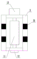
FIG. 2 is a schematic view of the structure of the grinding roll of the present invention;
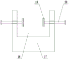
FIG. 3 is a schematic side view of a first riser of the present invention;
FIG. 4 is a schematic side view of a fixing plate according to the present invention;
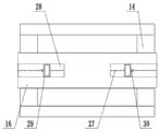
FIG. 5 is a schematic top view of the worktable according to the present invention.
FIG. 6 is a schematic top view of the slider of the present invention;
FIG. 7 is a schematic cross-sectional view of FIG. 6;
fig. 8 is a schematic structural view of the aluminum profile with the sliding plate placed therein.
In the figure: 1. a base; 2. a support plate; 3. a top plate; 4. a rectangular cavity; 5. a screw rod; 6. a first motor; 7. a rectangular block; 8. a vertical rod; 9. an inverted U-shaped frame; 10. a strip-shaped groove; 11. grinding a roller; 12. a connecting shaft; 13. a second motor; 14. a material collecting box; 15. a cylinder; 16. a work table; 17. a first vertical plate; 18. a U-shaped groove; 19. a first positioning block; 20. a first adjusting screw; 21. a second vertical plate; 22. a rotating shaft; 23. a fixing plate; 24. a circular groove; 25. a second positioning block; 26. a second adjusting screw; 27. a fixing hole; 28. a chute; 29. a moving block; 30. a square block; 31. fastening a bolt; 32. a servo motor; 33. a slide plate; 34. a magnet A; 35. and a magnet B.
Detailed Description
The technical solutions in the embodiments of the present invention will be clearly and completely described below with reference to the drawings in the embodiments of the present invention, and it is obvious that the described embodiments are only a part of the embodiments of the present invention, and not all of the embodiments. All other embodiments, which can be derived by a person skilled in the art from the embodiments given herein without making any creative effort, shall fall within the protection scope of the present invention.
The invention provides an aluminum profile polishing device as shown in figures 1-7, which comprises a base 1, two support plates 2 are fixedly arranged above the base 1, a top plate 3 is arranged at the inner side of the top end of each support plate 2, a rectangular cavity 4 is formed in the middle end of each top plate 3, a screw rod 5 is transversely arranged on the left inner side wall and the right inner side wall of each rectangular cavity 4, when the aluminum profile polishing device is specifically designed, one end of each screw rod 5 is rotatably connected to the left side wall of each rectangular cavity 4, the other end of each screw rod 5 penetrates through and extends to the outer side wall of each support plate 2 to be connected with a first motor 6 in a transmission manner, the first motor 6 is used for driving the screw rods 5 to rotate so as to move the rectangular blocks 7 left and right, rectangular blocks 7 are fixedly sleeved outside the screw rods 5 and positioned in the rectangular cavities 4, the bottom ends of the rectangular blocks 7, and bar groove 10 and 4 through connections of rectangle cavity set up, the other end of montant 8 runs through and extends to the fixed inverted U-shaped frame 9 that sets up through the connecting plate in the below of roof 3, inverted U-shaped frame 9 internally mounted sets up grinding roller 11, both ends are all rotated and are provided with connecting axle 12 about grinding roller 11, and the bottom of grinding roller 11 extends to the below of inverted U-shaped frame 9, the one end of connecting axle 12 runs through and extends to and rotates on the left side wall of inverted U-shaped frame 9 and set up the bearing frame, the other end of connecting axle 12 runs through and is connected with the transmission of second motor 13 on the right side wall of inverted U-shaped frame 9, can provide power to grinding roller 11.
A material collecting box 14 is arranged right above a base 1, air cylinders 15 are fixedly arranged at two ends of the top of the material collecting box 14, a workbench 16 is fixedly arranged on a telescopic shaft connected with the output end of the air cylinders 15, a first vertical plate 17 is fixedly arranged at the middle position of the top of the workbench 16, a U-shaped groove 18 is formed in the top end of the first vertical plate 17, positioning blocks 19 are symmetrically arranged on the left side and the right side in the U-shaped groove 18, a first adjusting screw 20 is fixedly connected with the other end of the positioning block 19, second vertical plates 21 are symmetrically arranged on the left side and the right side of the workbench 16 and positioned on the first vertical plate 17, a rotating shaft 22 is rotatably connected on the inner side wall of each second vertical plate 21, a fixing plate 23 is fixedly connected with the other end of the rotating shaft 22, a circular groove 24 is formed in the inner side wall of the fixing plate 23, four groups, the other ends of the first adjusting screw 20 and the second adjusting screw 26 respectively penetrate through and extend to the first vertical plate 17 and the outer side wall of the fixing plate 23 to be fixedly connected with a rotating rod, threaded holes are respectively formed in the first vertical plate 17 and the fixing plate 23 and in contact positions with the first adjusting screw 20 and the second adjusting screw 26 respectively, the first adjusting screw 20 and the second adjusting screw 26 can be adjusted and fixed, the first positioning block 19 and the second positioning block 25 are identical in structure and size, rubber pads are respectively adhered to the inner surfaces of the first positioning block 19 and the second positioning block 25, a good protection effect can be achieved, a servo motor 32 is fixedly installed on the outer side wall of the second vertical plate 21 on the right side of the workbench 16, the output end of the servo motor 32 is rotatably connected with one end of the,
the top bilateral symmetry of workstation 16 is provided with spout 28, sliding connection movable block 29 in spout 28, the top of movable block 29 and the bottom fixed connection of second riser 21, one side of movable block 29 just is located spout 28 internal fixation and sets up square piece 30, and the installation sets up fastening bolt 31 in square piece 30, fastening bolt 31's bottom is run through and is extended to the bottom of spout 28, can fix movable block 29 through fastening bolt 31, just set up a plurality of fixed orifices 27 with even and the equal clearance distribution in fastening bolt 31 corresponding position in the spout 28, be convenient for adjust the use.
When the aluminum profile polishing device is used, the middle part of an aluminum profile workpiece to be polished is placed on the U-shaped groove 18 in the first vertical plate 17, the moving block 29 is pushed according to the length of the aluminum profile to slide on the workbench 16, when the two ends of the aluminum profile are fixed, the fastening bolt 31 is screwed to be inserted into the fixing holes 27 in different positions in the sliding groove 28, the moving block 29 can be positioned, so that the fixing plate 23 on the inner side of the second vertical plate 21 is fixed with the two ends of the aluminum profile, the first adjusting screw 20 and the second adjusting screw 26 are rotationally adjusted by the rotating rod, the first positioning block 19 and the second positioning block 25 can be firmly fixed on the aluminum profile, the aluminum profile is ensured to be stably placed, the first motor 6 is started to drive the rectangular block 7 to move left and right in the rectangular cavity 4 under the rotating action of the screw rod 5, and the installation arrangement of the vertical rod 8 and the inverted U-shaped frame 9 is combined, start second motor 13 and connect under the rotation of connecting axle 12, can polish the processing through the surface of grinding roller 11 to the aluminium alloy, control cylinder 15 makes its telescopic shaft carry out jack-up upwards to workstation 16, can guarantee the aluminium alloy surface and grind roller 11 contact, in the process of polishing, twist and move first adjusting screw 20 and make locating piece 19 separately with the aluminium alloy, set up under the connection of rotation axis 22 and fixed plate 23 through starting servo motor 32, can realize the operation of turning over, be convenient for polish the use to the different faces of aluminium alloy, and the operation is simple.
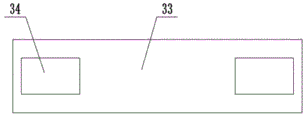
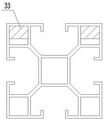
In addition, referring to fig. 2, fig. 6, fig. 7 and fig. 8, a pair of sliding plates 33 arranged in the aluminum profile is further designed, the top ends of two sides of each sliding plate 33 are provided with grooves, and magnets a34 are arranged in the grooves; two magnets B35 are fixedly arranged on two sides of the bottom end of the inverted U-shaped frame 9, the magnets B35 are located on two sides of the grinding roller 11, and the magnets B35 and the magnets A34 are arranged correspondingly. When the aluminum profile polishing device is used, the two sliding plates 33 are placed in the aluminum profile, when the polishing roller 11 is to be in contact with the aluminum profile, the magnet A34 and the magnet B35 attract each other, the aluminum profile keeps a certain levelness under the action of the sliding plates 33, and when the polishing roller 11 rubs the aluminum profile, the sliding plates 33 play a role in supporting and prevent the aluminum profile from deforming in the polishing process. When the grinding roller 11 moves along with the inverted U-shaped frame 9, the magnet A34 moves along with the magnet B35, and the aluminum profile is supported by the sliding plate 33 all the time in the grinding process. In order to make the sliding plate move smoothly along with the inverted U-shaped frame 9, the top end of the sliding plate 33 is smooth.
Finally, it should be noted that: although the present invention has been described in detail with reference to the foregoing embodiments, it will be apparent to those skilled in the art that modifications may be made to the embodiments or portions thereof without departing from the spirit and scope of the invention.
Claims (10)
1. The utility model provides an aluminium alloy processingequipment that polishes, includes base (1), its characterized in that: the grinding machine is characterized in that two supporting plates (2) are fixedly arranged above the base (1), a top plate (3) is arranged on the inner side of the top end of each supporting plate (2), a rectangular cavity (4) is formed in the middle end of the top plate (3), a lead screw (5) is transversely arranged on the left inner side wall and the right inner side wall of the rectangular cavity (4), a rectangular block (7) is fixedly sleeved outside the lead screw (5) and positioned in the rectangular cavity (4), one end of a vertical rod (8) is fixedly connected with the bottom end of the rectangular block (7), an inverted U-shaped frame (9) is fixedly arranged below the top plate (3) through a connecting plate, a grinding roller (11) is arranged inside the inverted U-shaped frame (9), connecting shafts (12) are rotatably arranged at the two ends of the grinding roller (11), and the bottom end of the grinding roller (11) extends to the lower side of the inverted U-shaped frame (9), the material collecting box is characterized in that a material collecting box (14) is arranged right above the base (1), cylinders (15) are fixedly arranged at two ends of the top of the material collecting box (14), a workbench (16) is fixedly arranged on a telescopic shaft connected with the output ends of the cylinders (15), a first vertical plate (17) is fixedly arranged at the middle position of the top of the workbench (16), a U-shaped groove (18) is formed in the top end of the first vertical plate (17), positioning blocks (19) are symmetrically arranged on the left side and the right side in the U-shaped groove (18), a first adjusting screw (20) is fixedly connected to the other end of the positioning block (19), a second vertical plate (21) is symmetrically arranged on the left side and the right side of the workbench (16) and positioned on the first vertical plate (17), a rotating shaft (22) is rotatably connected to the inner side wall of the second vertical plate (21), and a fixing plate (23), the improved structure of the hydraulic oil cylinder is characterized in that a circular groove (24) is formed in the inner side wall of the fixing plate (23), four groups of second positioning blocks (25) are distributed in the circular groove (24) in the inner circumference, the other ends of the second positioning blocks (25) are fixedly connected with a second adjusting screw (26), a servo motor (32) is fixedly installed on the outer side wall of a second vertical plate (21) on the right side of the workbench (16), the output end of the servo motor (32) is rotatably connected with one end of a rotating shaft (22), sliding grooves (28) are symmetrically formed in the two sides of the top of the workbench (16), a moving block (29) is connected in the sliding grooves (28), and the top of the moving block (29) is fixedly connected with the bottom.
2. The aluminum profile grinding processing device according to claim 1, characterized in that: one end of the screw rod (5) is rotatably connected to the left side wall of the rectangular cavity (4), and the other end of the screw rod (5) penetrates through and extends to the outer side wall of the supporting plate (2) to be connected with a first motor (6) in a transmission mode.
3. The aluminum profile grinding processing device according to claim 1, characterized in that: the bottom of the top plate (3) is provided with a strip-shaped groove (10) matched with the vertical rod (8), and the strip-shaped groove (10) is communicated with the rectangular cavity (4).
4. The aluminum profile grinding processing device according to claim 1, characterized in that: one end of the connecting shaft (12) penetrates through and extends to the left side wall of the inverted U-shaped frame (9) to be rotatably provided with a bearing seat, and the other end of the connecting shaft (12) penetrates through and extends to the right side wall of the inverted U-shaped frame (9) to be in transmission connection with the second motor (13).
5. The aluminum profile grinding processing device according to claim 1, characterized in that: the other end of first adjusting screw (20), second adjusting screw (26) runs through respectively and extends to fixedly connected with dwang on first riser (17), fixed plate (23) lateral wall, set up threaded hole all runs through in first riser (17) and fixed plate (23) and respectively with first adjusting screw (20), the position that contacts of second adjusting screw (26).
6. The aluminum profile grinding processing device according to claim 1, characterized in that: the first positioning block (19) and the second positioning block (25) are identical in structure and size, and rubber pads are arranged on the inner surfaces of the first positioning block and the second positioning block in an adhering mode.
7. The aluminum profile grinding processing device according to claim 1, characterized in that: one side of the moving block (29) is located in the sliding groove (28) and is fixedly provided with a square block (30), a fastening bolt (31) is arranged in the square block (30), and the bottom end of the fastening bolt (31) penetrates through and extends to the bottom of the sliding groove (28).
8. The aluminum profile grinding processing device according to claim 1, characterized in that: a plurality of fixing holes (27) are uniformly distributed at equal intervals in the sliding groove (28) and corresponding to the fastening bolts (31).
9. The aluminum profile grinding processing device according to claim 1, characterized in that: the aluminum profile is characterized by further comprising a pair of sliding plates (33) arranged in the aluminum profile, wherein grooves are formed in the top ends of two sides of each sliding plate (33), and magnets A (34) are arranged in the grooves; two magnets B (35) are fixedly arranged on two sides of the bottom end of the inverted U-shaped frame (9), the magnets B (35) are located on two sides of the grinding roller (11), and the magnets B (35) and the magnets A (34) are arranged correspondingly.
10. The aluminum profile grinding processing device according to claim 9, characterized in that: the top end of the sliding plate (33) is a smooth surface.
Priority Applications (1)
| Application Number | Priority Date | Filing Date | Title |
|---|---|---|---|
| CN202010110415.XA CN111203803A (en) | 2020-02-24 | 2020-02-24 | Aluminium alloy processingequipment that polishes |
Applications Claiming Priority (1)
| Application Number | Priority Date | Filing Date | Title |
|---|---|---|---|
| CN202010110415.XA CN111203803A (en) | 2020-02-24 | 2020-02-24 | Aluminium alloy processingequipment that polishes |
Publications (1)
| Publication Number | Publication Date |
|---|---|
| CN111203803A true CN111203803A (en) | 2020-05-29 |
Family
ID=70781207
Family Applications (1)
| Application Number | Title | Priority Date | Filing Date |
|---|---|---|---|
| CN202010110415.XA Withdrawn CN111203803A (en) | 2020-02-24 | 2020-02-24 | Aluminium alloy processingequipment that polishes |
Country Status (1)
| Country | Link |
|---|---|
| CN (1) | CN111203803A (en) |
Cited By (1)
| Publication number | Priority date | Publication date | Assignee | Title |
|---|---|---|---|---|
| CN112497009A (en) * | 2020-11-30 | 2021-03-16 | 青岛凯诚绿色建筑有限公司 | Seamless steel pipe intelligence rust cleaning maintenance of equipment for building site |
Citations (6)
| Publication number | Priority date | Publication date | Assignee | Title |
|---|---|---|---|---|
| US20080280542A1 (en) * | 2007-05-10 | 2008-11-13 | Kabushiki Kaisha Nihon Micronics | Cleaning apparatus for a probe |
| CN203236309U (en) * | 2013-04-18 | 2013-10-16 | 辽宁科技大学 | Magnetic grinding device for synchronously polishing inner surface and outer surface of straight pipe |
| CN205685133U (en) * | 2016-06-18 | 2016-11-16 | 李瑞静 | A kind of sanding apparatus of aluminium alloy extrusions |
| CN106271026A (en) * | 2016-08-25 | 2017-01-04 | 南京理工大学 | Utilize the method and apparatus that electromagnetic technique realizes agitating friction weldering flexible interior support |
| CN207656417U (en) * | 2017-12-09 | 2018-07-27 | 江苏金海铝业有限公司 | A kind of comprehensive grinding device of aluminium |
| CN209207155U (en) * | 2018-11-29 | 2019-08-06 | 镇江隆耀金属材料有限公司 | A kind of processing unit (plant) of aluminium sheet circle |
-
2020
- 2020-02-24 CN CN202010110415.XA patent/CN111203803A/en not_active Withdrawn
Patent Citations (6)
| Publication number | Priority date | Publication date | Assignee | Title |
|---|---|---|---|---|
| US20080280542A1 (en) * | 2007-05-10 | 2008-11-13 | Kabushiki Kaisha Nihon Micronics | Cleaning apparatus for a probe |
| CN203236309U (en) * | 2013-04-18 | 2013-10-16 | 辽宁科技大学 | Magnetic grinding device for synchronously polishing inner surface and outer surface of straight pipe |
| CN205685133U (en) * | 2016-06-18 | 2016-11-16 | 李瑞静 | A kind of sanding apparatus of aluminium alloy extrusions |
| CN106271026A (en) * | 2016-08-25 | 2017-01-04 | 南京理工大学 | Utilize the method and apparatus that electromagnetic technique realizes agitating friction weldering flexible interior support |
| CN207656417U (en) * | 2017-12-09 | 2018-07-27 | 江苏金海铝业有限公司 | A kind of comprehensive grinding device of aluminium |
| CN209207155U (en) * | 2018-11-29 | 2019-08-06 | 镇江隆耀金属材料有限公司 | A kind of processing unit (plant) of aluminium sheet circle |
Cited By (1)
| Publication number | Priority date | Publication date | Assignee | Title |
|---|---|---|---|---|
| CN112497009A (en) * | 2020-11-30 | 2021-03-16 | 青岛凯诚绿色建筑有限公司 | Seamless steel pipe intelligence rust cleaning maintenance of equipment for building site |
Similar Documents
| Publication | Publication Date | Title |
|---|---|---|
| CN210997460U (en) | Cutting and grinding device for magnet machining | |
| CN111203803A (en) | Aluminium alloy processingequipment that polishes | |
| CN211388744U (en) | Scribing table for machining | |
| CN209936575U (en) | Grinding device is used in bearing processing of convenient regulation | |
| CN112157545A (en) | Grinding device for hardware machining capable of adjusting angle in multiple directions | |
| CN216681469U (en) | Aluminum plate double-side polishing device | |
| CN213164631U (en) | Jewelry silver material burnishing and polishing machine | |
| CN216228364U (en) | Full-automatic rotor forming special equipment for automobile engine | |
| CN213592455U (en) | Grinding device is used in production of indoor lamp shade | |
| CN212601692U (en) | Machining fixed station | |
| CN211163364U (en) | Multifunctional automatic grinding machine | |
| CN210335444U (en) | Clamping device for polishing mechanical parts | |
| CN211760594U (en) | Grinding device for production of movable valve | |
| CN215281352U (en) | Three-station polishing machine based on mechanical polishing | |
| CN219967487U (en) | Magnesium board surface treatment device | |
| CN219170429U (en) | Polishing device for metal materials | |
| CN218613206U (en) | Fixing device for polishing end face of cylindrical roller | |
| CN220806784U (en) | Polishing device | |
| CN204867644U (en) | Two -sided edging machine of full -automatic diamond saw blade | |
| CN215432913U (en) | Grinding device is used in switch board processing | |
| CN216030002U (en) | Sculpture processing fixing device that polishes | |
| CN217493458U (en) | Spline shaft machining clamp | |
| CN220408303U (en) | Spare part burnishing device that machining used | |
| CN220279117U (en) | Surface treatment device for building templates | |
| CN213196598U (en) | Vertical linear rail machining center |
Legal Events
| Date | Code | Title | Description |
|---|---|---|---|
| PB01 | Publication | ||
| PB01 | Publication | ||
| SE01 | Entry into force of request for substantive examination | ||
| SE01 | Entry into force of request for substantive examination | ||
| WW01 | Invention patent application withdrawn after publication |
Application publication date: 20200529 |
|
| WW01 | Invention patent application withdrawn after publication |