CN111188552B - A detachable door cover and its assembly method - Google Patents
A detachable door cover and its assembly method Download PDFInfo
- Publication number
- CN111188552B CN111188552B CN202010057330.XA CN202010057330A CN111188552B CN 111188552 B CN111188552 B CN 111188552B CN 202010057330 A CN202010057330 A CN 202010057330A CN 111188552 B CN111188552 B CN 111188552B
- Authority
- CN
- China
- Prior art keywords
- plates
- plate
- clamping
- sleeve plates
- wall
- Prior art date
- Legal status (The legal status is an assumption and is not a legal conclusion. Google has not performed a legal analysis and makes no representation as to the accuracy of the status listed.)
- Active
Links
Images


Classifications
-
- E—FIXED CONSTRUCTIONS
- E06—DOORS, WINDOWS, SHUTTERS, OR ROLLER BLINDS IN GENERAL; LADDERS
- E06B—FIXED OR MOVABLE CLOSURES FOR OPENINGS IN BUILDINGS, VEHICLES, FENCES OR LIKE ENCLOSURES IN GENERAL, e.g. DOORS, WINDOWS, BLINDS, GATES
- E06B1/00—Border constructions of openings in walls, floors, or ceilings; Frames to be rigidly mounted in such openings
- E06B1/04—Frames for doors, windows, or the like to be fixed in openings
- E06B1/34—Coverings, e.g. protecting against weather, for decorative purposes
-
- E—FIXED CONSTRUCTIONS
- E06—DOORS, WINDOWS, SHUTTERS, OR ROLLER BLINDS IN GENERAL; LADDERS
- E06B—FIXED OR MOVABLE CLOSURES FOR OPENINGS IN BUILDINGS, VEHICLES, FENCES OR LIKE ENCLOSURES IN GENERAL, e.g. DOORS, WINDOWS, BLINDS, GATES
- E06B1/00—Border constructions of openings in walls, floors, or ceilings; Frames to be rigidly mounted in such openings
- E06B1/56—Fastening frames to the border of openings or to similar contiguous frames
- E06B1/60—Fastening frames to the border of openings or to similar contiguous frames by mechanical means, e.g. anchoring means
-
- E—FIXED CONSTRUCTIONS
- E06—DOORS, WINDOWS, SHUTTERS, OR ROLLER BLINDS IN GENERAL; LADDERS
- E06B—FIXED OR MOVABLE CLOSURES FOR OPENINGS IN BUILDINGS, VEHICLES, FENCES OR LIKE ENCLOSURES IN GENERAL, e.g. DOORS, WINDOWS, BLINDS, GATES
- E06B3/00—Window sashes, door leaves, or like elements for closing wall or like openings; Layout of fixed or moving closures, e.g. windows in wall or like openings; Features of rigidly-mounted outer frames relating to the mounting of wing frames
- E06B3/96—Corner joints or edge joints for windows, doors, or the like frames or wings
Landscapes
- Engineering & Computer Science (AREA)
- Civil Engineering (AREA)
- Structural Engineering (AREA)
- Mechanical Engineering (AREA)
- Joining Of Corner Units Of Frames Or Wings (AREA)
Abstract
The invention belongs to the technical field of decoration and particularly relates to a detachable door pocket and an assembling method thereof, wherein the detachable door pocket comprises two outer sleeve plates, four vertical frame bodies, two transverse frame bodies, three top sleeve plates and two inner sleeve plates, the two inner sleeve plates are fixed on the side wall of a wall through rivets, outer snap plates extending inwards are arranged on the outer edges of the inner sleeve plates, the outer snap plates are perpendicular to the inner sleeve plates, and the two inner snap plates are fixed on the inner sides of the outer sleeve plates; the utility model discloses a vertical framework, including the outer lagging plate, the outer lagging plate is fixed a position with the rivet, and the cooperation of outer lagging plate and inner lagging plate is hidden the rivet, improve the aesthetic property, utilize L type trip in the vertical framework to fix outer lagging plate and inner lagging plate, do not need contact glue, be favorable to dismantling, and can not give off the smell of glue, improve the environmental protection travelling comfort of fitment, can realize the installation of top structure, and prescribe a limit to the high position of vertical framework simultaneously, guarantee that the structure is firm reliable, also be favorable to the dismantlement in later stage.
Description
Technical Field
The invention belongs to the technical field of decoration and particularly relates to a detachable door pocket and an assembling method thereof.
Background
The door pocket is a building decoration term, refers to two door frames inside and outside the door, also has directly to be called the door frame, and its main effect is fixed door leaf and protection corner, decoration etc. along with the improvement of people's standard of living, people pay more and more attention to the decoration of family, in order to beautify oneself living environment, people do not save to spend a large amount of funds on fitment, and in the decoration process, the fitment of door pocket has become essential decoration content. The traditional decoration mode is that a layer of density board is fixed at the position of a doorway by woodworker's hands, and then a decoration surface is bonded on the density board, the mode is operated by hands, which is labor-consuming, time-consuming and labor-consuming, and a large amount of viscose is used in the construction process, most of the viscose is harmful to human bodies, and after decoration is finished, the smell of the viscose can not be dispersed for a long time.
In addition, because the viscose comes the bonding fixedly, inconvenient dismantlement, and door pocket bottom wets the back, has the condition of fracture or corruption, just at this moment need dismantle the door pocket, changes, just so that be not convenient for construct at this moment, even need damage the wall when serious.
Disclosure of Invention
The invention provides a detachable door pocket and an assembling method thereof, which aim to solve the problems in the background technology.
In order to achieve the purpose, the invention provides the following technical scheme: a detachable door pocket comprises two outer sleeve plates, four vertical frame bodies, two transverse frame bodies, three top sleeve plates and two inner sleeve plates, wherein the two inner sleeve plates are fixed on the side wall of a wall through rivets, outer clamping plates extending towards the inner sides are arranged on the outer edges of the inner sleeve plates, the outer clamping plates are perpendicular to the inner sleeve plates, two inner clamping plates are fixed on the inner sides of the outer sleeve plates and are attached to the inner walls of the outer clamping plates, the edges of the outer sleeve plates are flush with the edges of the inner sleeve plates, clamping grooves are formed in the inner clamping plates and the outer clamping plates, the positions of the clamping grooves in the inner clamping plates and the outer clamping plates correspond, L-shaped clamping hooks are arranged on the vertical frame bodies, the L-shaped clamping hooks are connected with the clamping grooves in a clamping mode, the three top sleeve plates are fixed at the top of the wall through the rivets, one transverse frame body is provided with a frame plate and a bottom sealing plate which are matched with the top sleeve plates, and a limiting column clamped with the frame plate is arranged on the other transverse frame body, and clamping inclined planes matched with the outer sleeve plate are arranged at two ends of the transverse frame body.
Preferably, the width of the L-shaped clamping hook is equal to two thirds of the width of the inner clamping plate and the width of the outer clamping plate, and the width of the inner clamping plate and the width of the outer clamping plate are at least five centimeters.
Preferably, one end of the vertical frame body extends to the wall, and the other end of the vertical frame body extends to the edge of the outer sleeve plate.
Preferably, the shape of the clamping grooves is rectangular, and the number of the clamping grooves is at least five.
Preferably, the L-shaped clamping hook comprises a mounting plate, an extending portion and a limiting portion, a sinking groove is formed in the inner side of the vertical frame body, the mounting plate is fixed in the sinking groove through a screw, the limiting portion is fixed on the mounting plate through the extending portion, and the length of the limiting portion is equal to the height of the clamping groove.
Preferably, the cross section of the top sleeve plate is in an inverted U shape, the lower end of the top sleeve plate is provided with a limiting hook portion extending inwards, the limiting hook portion is horizontally arranged, and the frame plate is located on the upper end face of the limiting hook portion.
Preferably, the distance between the lower end surface of the frame plate and the upper end surface of the bottom sealing plate is equal to the thickness of the limiting hook part.
Preferably, the number of the limiting columns is three times that of the frame plates, and positioning grooves matched with the limiting columns are formed in the inner sides of the frame plates.
A method for assembling a detachable door pocket comprises the following steps:
step S1, fixing the inner sleeve plate on the wall by using a rivet, and clamping the inner clamping plate of the outer sleeve plate on the inner side of the outer clamping plate;
step S2, clamping L-shaped clamping hooks on the inner sides of the four vertical frame bodies in clamping grooves on the inner clamping plates and the outer clamping plates;
step S3, fixing the three top sleeve plates on the top of the wall by using rivets, and then clamping the transverse frame body with the frame plates in the top sleeve plates;
and step S4, clamping the transverse frame body with the limiting column on the wall on the other side, and enabling the limiting column to penetrate through the frame plate during clamping.
Compared with the prior art, the invention has the beneficial effects that:
according to the invention, the two inner sleeve plates are fixed on the side wall of the wall through rivets, the outer edges of the inner sleeve plates are provided with outer clamping plates extending inwards, the outer clamping plates are perpendicular to the inner sleeve plates, the inner sides of the outer sleeve plates are fixed with two inner clamping plates, the inner clamping plates are attached to the inner walls of the outer clamping plates, the edges of the outer sleeve plates are flush with the edges of the inner sleeve plates, the inner sleeve plates are positioned through the rivets, and the rivets are hidden through the matching of the outer sleeve plates and the inner sleeve plates, so that the attractiveness is improved;
According to the invention, the inner clamping plate and the outer clamping plate are both provided with the clamping grooves, the positions of the clamping grooves on the inner clamping plate and the outer clamping plate correspond to each other, the vertical frame body is provided with the L-shaped clamping hook, the L-shaped clamping hook is clamped and connected with the clamping grooves, and the outer sleeve plate and the inner sleeve plate are fixed by utilizing the L-shaped clamping hook on the vertical frame body without contacting glue water, so that the disassembly is facilitated, the smell of the glue water cannot be emitted, and the environment-friendly comfort of decoration is improved;
according to the invention, the three top sleeve plates are fixed on the top of the wall through the rivets, one transverse frame body is provided with the frame plate and the bottom sealing plate which are matched with the top sleeve plates, the other transverse frame body is provided with the limiting column clamped with the frame plate, and the two ends of the transverse frame body are provided with the clamping inclined planes matched with the outer sleeve plates, so that the mounting of a top structure can be realized, the height position of the vertical frame body is limited, the stability and reliability of the structure are ensured, and the later-stage disassembly is facilitated.
Drawings
The accompanying drawings, which are included to provide a further understanding of the invention and are incorporated in and constitute a part of this specification, illustrate embodiments of the invention and together with the description serve to explain the principles of the invention and not to limit the invention. In the drawings:
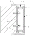
FIG. 1 is a schematic view of the structure of the present invention;
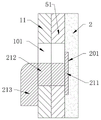
FIG. 2 is a schematic view of the engagement between the outer race plate and the vertical frame in the present invention;
FIG. 3 is a schematic structural view of an L-shaped hook according to the present invention;
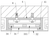
FIG. 4 is a schematic view of the engagement between the top sheathing and the lateral frame of the present invention;
fig. 5 is a schematic structural view of the transverse frame body in the invention.
In the figure: 1. an outer race plate; 101. a card slot; 11. an inner snap plate; 2. a vertical frame body; 201. sinking a groove; 21. an L-shaped hook; 211. mounting a plate; 212. an extension portion; 213. a limiting part; 3. a transverse frame; 31. a frame plate; 311. positioning a groove; 32. a bottom sealing plate; 33. clamping the inclined plane; 34. a limiting column; 4. a top deck; 41. a limiting hook part; 5. an inner race plate; 51. an outer plywood; 6. and (4) riveting.
Detailed Description
The technical solutions in the embodiments of the present invention will be clearly and completely described below with reference to the drawings in the embodiments of the present invention, and it is obvious that the described embodiments are only a part of the embodiments of the present invention, and not all of the embodiments. All other embodiments, which can be derived by a person skilled in the art from the embodiments given herein without making any creative effort, shall fall within the protection scope of the present invention.
Referring to fig. 1-5, the present invention provides the following technical solutions: a detachable door pocket comprises two outer sleeve plates 1, four vertical frame bodies 2, two transverse frame bodies 3, three top sleeve plates 4 and two inner sleeve plates 5, wherein the two inner sleeve plates 5 are fixed on the side wall of a wall through rivets 6, the rivets 6 are driven into the wall through tools, then holes with corresponding sizes are formed in the inner sleeve plates 5, finally nuts are screwed on the rear sections of the rivets 6 for positioning, outer snap plates 51 extending towards the inner sides are arranged on the outer edges of the inner sleeve plates 5, the outer snap plates 51 are perpendicular to the inner sleeve plates 5, two inner snap plates 11 are fixed on the inner sides of the outer sleeve plates 1, the inner snap plates 11 are attached to the inner walls of the outer snap plates 51, the edges of the outer sleeve plates 1 are flush with the edges of the inner sleeve plates 5, the appearance attractiveness can be guaranteed, and the decoration can be conveniently added to the outer sleeve plates 1 in the later period, the inner snap plates 11 and the outer snap plates 51 are both provided with a clamping groove 101, and the positions of the clamping grooves 101 on the inner snap plates 11 and the outer snap plates 51 correspond, be equipped with L type trip 21 on the vertical framework 2, L type trip 21 is connected with draw-in groove 101 block, and three top lagging 4 passes through rivet 6 to be fixed at the top of wall, and one of them horizontal framework 3 is equipped with top lagging 4 complex deckle board 31 and end shrouding 32, is equipped with the spacing post 34 with deckle board 31 block on another horizontal framework 3, and the both ends of horizontal framework 3 are equipped with outer lagging 1 complex block inclined plane 33.
In this embodiment, the inner sheathing plate 5 is fixed to the wall by the rivet 6, and the inner snap plate 11 of the outer sheathing plate 1 is snapped inside the outer snap plate 51; the L-shaped clamping hooks 21 on the inner sides of the four vertical frame bodies 2 are clamped in the clamping grooves 101 on the inner clamping plates 11 and the outer clamping plates 51; fixing the three top sleeve plates 4 on the top of the wall by using rivets 6, and then clamping the transverse frame body 3 with the frame plates 31 in the top sleeve plates 4; then the transverse frame body 3 with the limiting column 34 is clamped on the wall at the other side, the limiting column 34 penetrates through the frame plate 31 during clamping, when the device is disassembled, the device is firstly absorbed on one transverse frame body 3 by using a sucking disc, then horizontally applies force to draw outwards, so that the limiting column 34 slides in the frame plate 31, the two transverse frame bodies 3 are separated, after one transverse frame body 3 is drawn, then another transverse frame body 3 is pulled to enable the frame plate 31 and the bottom sealing plate 32 to slide on the upper end surface and the lower end surface of the limiting hook part 41, then, after the two horizontal frames 3 are completely detached, the vertical frame 2 is moved upward to make the position-limiting portion 213 slide on the inner wall of the inner engaging plate 11 until the position-limiting portion 213 slides into the engaging groove 101 to disengage the position-limiting portion 213, then draw outward draw vertical framework 2 can, four vertical frameworks 2 dismantle the completion after, just can demolish the interior removal of outer sleeve plate 1, accomplish the dismantlement, be convenient for change vertical framework 2 or outer sleeve plate 1 of damage.
Specifically, the width of the L-shaped hook 21 is equal to two thirds of the width of the inner engaging plate 11 and the outer engaging plate 51, and the width of the inner engaging plate 11 and the outer engaging plate 51 is at least five centimeters, so that the stability of the engagement can be improved.
Specifically, one end of the vertical frame body 2 extends to the wall, and the other end of the vertical frame body 2 extends to the edge of the outer sleeve plate 1, so that the attractiveness and the coverage are guaranteed.
Specifically, the shape of the slots 101 is rectangular, and the number of the slots 101 is at least five, so that the bearing strength between the vertical frame body 2 and the inner snap plate 11 and between the vertical frame body and the outer snap plate 51 can be improved.
Specifically, the L-shaped hook 21 includes a mounting plate 211, an extending portion 212, and a limiting portion 213, a sunk groove 201 is formed in the inner side of the vertical frame 2, the mounting plate 211 is fixed in the sunk groove 201 by a screw, the limiting portion 213 is fixed on the mounting plate 211 by the extending portion 212, the length of the limiting portion 213 is equal to the height of the slot 101, the mounting plate 211, the extending portion 212, and the limiting portion 213 are made of a metal material, and the bearing capacity of the engagement with the inner locking plate 11 and the outer locking plate 51 can be improved.
Specifically, the cross section of top lagging 4 is the U type of inversion, and the lower extreme of top lagging 4 is equipped with the spacing hook portion 41 of inside extension, and spacing hook portion 41 level is arranged, and the frame plate 31 is located the up end of spacing hook portion 41, can provide the platform of support for frame plate 31 through such structural design, the installation of being convenient for.
Specifically, the distance between the lower end surface of the frame plate 31 and the upper end surface of the bottom sealing plate 32 is equal to the thickness of the limiting hook 41, and the compact design can ensure that the frame plate 31 and the bottom sealing plate 32 have high stability when being mounted on the limiting hook 41.
Specifically, the number of the limiting columns 34 is three times that of the frame plate 31, the positioning grooves 311 matched with the limiting columns 34 are formed in the inner side of the frame plate 31, the connecting strength and the bearing strength between the limiting columns 34 and the frame plate 31 can be increased through the three times of the limiting columns 34, and the positioning grooves 311 guarantee the stability of clamping.
The assembling method of the detachable door pocket comprises the following steps:
step S1, fixing the inner sleeve plate 5 on the wall by using the rivet 6, and clamping the inner clamping plate 11 of the outer sleeve plate 1 on the inner side of the outer clamping plate 51;
step S2, clamping the L-shaped clamping hooks 21 at the inner sides of the four vertical frame bodies 2 in the clamping grooves 101 on the inner clamping plate 11 and the outer clamping plate 51;
step S3, fixing the three top sleeve plates 4 on the top of the wall by using rivets 6, and then clamping the transverse frame body 3 with the frame plate 31 in the top sleeve plates 4;
step S4, the transverse frame 3 with the position-limiting post 34 is clamped on the wall on the other side, and the position-limiting post 34 passes through the frame plate 31 during clamping.
The working principle and the using process of the invention are as follows: firstly, fixing an inner sleeve plate 5 on a wall by using a rivet 6, and clamping an inner clamping plate 11 of an outer sleeve plate 1 on the inner side of an outer clamping plate 51; the L-shaped clamping hooks 21 at the inner sides of the four vertical frame bodies 2 are clamped in the clamping grooves 101 on the inner clamping plates 11 and the outer clamping plates 51; fixing the three top sleeve plates 4 on the top of the wall by using rivets 6, and then clamping the transverse frame body 3 with the frame plates 31 in the top sleeve plates 4; then the transverse frame body 3 with the limit post 34 is clamped on the wall at the other side, when in clamping, the limit post 34 passes through the frame plate 31, when the device is disassembled, the device is firstly adsorbed on one transverse frame body 3 by using the sucking disc, then the device is horizontally forced to pull outwards, the limit column 34 slides in the frame plate 31, the two transverse frame bodies 3 are separated, after one transverse frame body 3 is pulled, the other transverse frame body 3 is pulled to make the frame plate 31 and the bottom sealing plate 32 slide on the upper and lower end surfaces of the limiting hook part 41, then, after the two horizontal frame bodies 3 are completely disassembled, the vertical frame body 2 is moved upwards to make the limiting part 213 slide on the inner wall of the inner clamping plate 11 until the limiting part 213 slides into the clamping groove 101 to make the limiting part 213 depart, then draw outward draw vertical framework 2 can, four vertical frameworks 2 dismantle the completion after, just can demolish the interior removal of outer sleeve plate 1, accomplish the dismantlement, be convenient for change vertical framework 2 or outer sleeve plate 1 of damage.
Finally, it should be noted that: although the present invention has been described in detail with reference to the foregoing embodiments, it will be apparent to those skilled in the art that modifications may be made to the embodiments described above, or equivalents may be substituted for elements thereof. Any modification, equivalent replacement, or improvement made within the spirit and principle of the present invention should be included in the protection scope of the present invention.
Claims (9)
1. The utility model provides a detachable door pocket which characterized in that: comprises two outer sleeve plates (1), four vertical frame bodies (2), two transverse frame bodies (3), three top sleeve plates (4) and two inner sleeve plates (5), two the inner sleeve plates (5) are fixed on the side wall of the wall through rivets (6), outer snap plates (51) extending towards the inner sides are arranged on the outer edges of the inner sleeve plates (5), the outer snap plates (51) are vertical to the inner sleeve plates (5), two inner snap plates (11) are fixed on the inner sides of the outer sleeve plates (1), the inner snap plates (11) are pasted on the inner walls of the outer snap plates (51), the edges of the outer sleeve plates (1) are flush with the edges of the inner sleeve plates (5), clamping grooves (101) are formed in the inner snap plates (11) and the outer snap plates (51), and the positions of the clamping grooves (101) on the inner snap plates (11) and the outer snap plates (51) correspond to each other, be equipped with L type trip (21) on vertical framework (2), L type trip (21) with draw-in groove (101) block is connected, and is three top lagging (4) are passed through fix at the top of wall in rivet (6), one of them horizontal framework (3) are equipped with three top lagging (4) all carries out complex frame plate (31) and end shrouding (32), another be equipped with on horizontal framework (3) with spacing post (34) of frame plate (31) block, the both ends of horizontal framework (3) be equipped with vertical framework (2) complex block inclined plane (33).
2. The detachable door pocket according to claim 1, wherein: the width of L type trip (21) equals interior cardboard (11) and two-thirds of outer cardboard (51) width, the width of interior cardboard (11) and outer cardboard (51) is five centimetres at least.
3. The detachable door pocket according to claim 1, wherein: one end of the vertical frame body (2) extends to the wall, and the other end of the vertical frame body (2) extends to the edge of the outer sleeve plate (1).
4. A removable door jamb as set forth in claim 1, wherein: the shape of draw-in groove (101) is the rectangle, the quantity of draw-in groove (101) is five at least.
5. A removable door jamb as set forth in claim 1, wherein: l type trip (21) include mounting panel (211), extension (212) and spacing portion (213), heavy groove (201) have been seted up to the inboard of vertical frame body (2), mounting panel (211) pass through the fix with screw in heavy groove (201), just spacing portion (213) pass through extension (212) are fixed on mounting panel (211), just the length of spacing portion (213) equals the height of draw-in groove (101).
6. The detachable door pocket according to claim 1, wherein: the cross section of top lagging (4) is the U type of invering, the lower extreme of top lagging (4) is equipped with inside extension's spacing hook portion (41), spacing hook portion (41) level is arranged, framed panel (31) is located the up end of spacing hook portion (41).
7. The detachable door pocket according to claim 6, wherein: the distance between the lower end face of the frame plate (31) and the upper end face of the bottom sealing plate (32) is equal to the thickness of the limiting hook part (41).
8. The detachable door pocket according to claim 1, wherein: the number of the limiting columns (34) is three times that of the frame plates (31), and positioning grooves (311) matched with the limiting columns (34) are formed in the inner sides of the frame plates (31).
9. The method of assembling a removable door jamb of claim 1, wherein: the method comprises the following steps: step S1, fixing the inner sleeve plate (5) on the wall by using a rivet (6), and clamping the inner clamping plate (11) of the outer sleeve plate (1) on the inner side of the outer clamping plate (51); s2, clamping L-shaped clamping hooks (21) on the inner sides of the four vertical frame bodies (2) in clamping grooves (101) on an inner clamping plate (11) and an outer clamping plate (51); step S3, fixing the three top sleeve plates (4) on the top of the wall by using rivets (6), and then clamping the transverse frame body (3) with the frame plate (31) in the top sleeve plates (4); and step S4, clamping the transverse frame body (3) with the limiting column (34) on the wall on the other side, and enabling the limiting column (34) to penetrate through the frame plate (31) during clamping.
Priority Applications (1)
| Application Number | Priority Date | Filing Date | Title |
|---|---|---|---|
| CN202010057330.XA CN111188552B (en) | 2020-01-19 | 2020-01-19 | A detachable door cover and its assembly method |
Applications Claiming Priority (1)
| Application Number | Priority Date | Filing Date | Title |
|---|---|---|---|
| CN202010057330.XA CN111188552B (en) | 2020-01-19 | 2020-01-19 | A detachable door cover and its assembly method |
Publications (2)
| Publication Number | Publication Date |
|---|---|
| CN111188552A CN111188552A (en) | 2020-05-22 |
| CN111188552B true CN111188552B (en) | 2022-06-28 |
Family
ID=70704134
Family Applications (1)
| Application Number | Title | Priority Date | Filing Date |
|---|---|---|---|
| CN202010057330.XA Active CN111188552B (en) | 2020-01-19 | 2020-01-19 | A detachable door cover and its assembly method |
Country Status (1)
| Country | Link |
|---|---|
| CN (1) | CN111188552B (en) |
Family Cites Families (6)
| Publication number | Priority date | Publication date | Assignee | Title |
|---|---|---|---|---|
| CA2214734A1 (en) * | 1997-09-08 | 1999-03-08 | Royal Group Technologies Limited | Composite door frames |
| CN100577981C (en) * | 2007-11-26 | 2010-01-06 | 程礼中 | Door and window covers that can be cut and used at will |
| CN103046841A (en) * | 2013-01-04 | 2013-04-17 | 张飞龙 | Wrapping structure for decorative door |
| CN103410405B (en) * | 2013-08-24 | 2016-05-18 | 程礼中 | Exempt from out end cap slot and can cut the formula of the giving up the throne door and window cover of closing in |
| CN104110199A (en) * | 2014-08-11 | 2014-10-22 | 湖州铁佛耐火材料有限公司 | Novel fireproof door frame with inserted door sleeve |
| CN104790806A (en) * | 2015-04-20 | 2015-07-22 | 江苏好太太家居建材有限公司 | Indoor invisible door |
-
2020
- 2020-01-19 CN CN202010057330.XA patent/CN111188552B/en active Active
Also Published As
| Publication number | Publication date |
|---|---|
| CN111188552A (en) | 2020-05-22 |
Similar Documents
| Publication | Publication Date | Title |
|---|---|---|
| CN201187131Y (en) | Folding angle veneer | |
| CN206000349U (en) | Partition wall door opening structure | |
| CN111188552B (en) | A detachable door cover and its assembly method | |
| CN205153232U (en) | Glass curtain wall crossbeam connected system | |
| CN204551843U (en) | The outer broken line type frame-supported glass curtain wall choosing glass wing of band | |
| CN212249168U (en) | Combined building template for constructional engineering | |
| CN206346665U (en) | A kind of door-plate package assembly and furniture | |
| CN204385895U (en) | Folding container room | |
| CN206448421U (en) | A hanging type open aluminum alloy panel curtain wall system | |
| CN210117897U (en) | A decorative line interface connection structure with anti-collision reinforcement function | |
| CN211572149U (en) | Ventilation type heat preservation curtain for building | |
| CN202124979U (en) | Aluminium board sub frame of all-hidden frame aluminium alloy glass curtain wall | |
| CN202809939U (en) | Frame-hidden corner upright column capable of opening window | |
| CN202148622U (en) | Exposed frame aluminum alloy beam buckle cover profile of glass curtain wall | |
| CN218814907U (en) | A seamless decorative panel | |
| CN207812817U (en) | A kind of wall barrier plate not gluing composite plate | |
| CN209025213U (en) | A kind of mobile house with assembled wall | |
| CN222797344U (en) | A window frame connection structure | |
| CN203230307U (en) | Sliding door with decorated frame | |
| CN218623532U (en) | Container connecting assembly | |
| CN214144138U (en) | An energy-saving prefab house structure that is easy to assemble | |
| CN113530076B (en) | Multifunctional assembled suspended ceiling edging butt joint module | |
| CN208310552U (en) | A kind of horizontal frame of aluminium door | |
| CN212897064U (en) | Fixing structure of hidden frame curtain wall glass plate | |
| CN223867893U (en) | Aluminum door cover plate section bar, aluminum door keel and aluminum door frame composite section bar |
Legal Events
| Date | Code | Title | Description |
|---|---|---|---|
| PB01 | Publication | ||
| PB01 | Publication | ||
| SE01 | Entry into force of request for substantive examination | ||
| SE01 | Entry into force of request for substantive examination | ||
| GR01 | Patent grant | ||
| GR01 | Patent grant | ||
| PE01 | Entry into force of the registration of the contract for pledge of patent right | ||
| PE01 | Entry into force of the registration of the contract for pledge of patent right |
Denomination of invention: A detachable door frame and its assembly method Granted publication date: 20220628 Pledgee: Dongguan Rural Commercial Bank Co.,Ltd. Zhangmutou Branch Pledgor: DONGGUAN ZHONGJIN FURNITURE Co.,Ltd. Registration number: Y2025980060269 |