CN111174392A - Assembly structure and assembly method of airflow controller and air conditioner - Google Patents
Assembly structure and assembly method of airflow controller and air conditioner Download PDFInfo
- Publication number
- CN111174392A CN111174392A CN201811347373.0A CN201811347373A CN111174392A CN 111174392 A CN111174392 A CN 111174392A CN 201811347373 A CN201811347373 A CN 201811347373A CN 111174392 A CN111174392 A CN 111174392A
- Authority
- CN
- China
- Prior art keywords
- supporting
- air
- shell
- plate
- limiting plate
- Prior art date
- Legal status (The legal status is an assumption and is not a legal conclusion. Google has not performed a legal analysis and makes no representation as to the accuracy of the status listed.)
- Granted
Links
Images


Classifications
-
- F—MECHANICAL ENGINEERING; LIGHTING; HEATING; WEAPONS; BLASTING
- F24—HEATING; RANGES; VENTILATING
- F24F—AIR-CONDITIONING; AIR-HUMIDIFICATION; VENTILATION; USE OF AIR CURRENTS FOR SCREENING
- F24F11/00—Control or safety arrangements
- F24F11/89—Arrangement or mounting of control or safety devices
-
- F—MECHANICAL ENGINEERING; LIGHTING; HEATING; WEAPONS; BLASTING
- F24—HEATING; RANGES; VENTILATING
- F24F—AIR-CONDITIONING; AIR-HUMIDIFICATION; VENTILATION; USE OF AIR CURRENTS FOR SCREENING
- F24F13/00—Details common to, or for air-conditioning, air-humidification, ventilation or use of air currents for screening
- F24F13/20—Casings or covers
- F24F2013/207—Casings or covers with control knobs; Mounting controlling members or control units therein
Abstract
The invention provides an assembly structure and an assembly method of an airflow controller and an air conditioner, the assembly structure of the airflow controller comprises a first supporting shell, a second supporting shell, a third shell and a fourth shell which are sequentially arranged from top to bottom, the first supporting shell and the second supporting shell are detachably connected to form an airflow controller supporting device, the third shell and the fourth shell are detachably connected to form an airflow controller accommodating device, the airflow controller accommodating device and the airflow controller supporting device are assembled to form a fixing device of the airflow controller, a first supporting part is arranged on the first supporting shell, a second supporting part is arranged on the second supporting shell, a first accommodating cavity is formed between the first supporting part and the second supporting part, and the airflow controller is used for changing the direction of the gas in the first accommodating cavity. The assembly structure of the air flow controller provided by the invention is reasonable in structure, convenient and fast to assemble, stable and reliable.
Description
Technical Field
The invention relates to the technical field of air conditioners, in particular to an assembly structure and an assembly method of an airflow controller and an air conditioner.
Background
The air conditioner has been widely used in thousands of households, a casing of an indoor unit of the air conditioner is an important part of the air conditioner, many parts of the air conditioner, such as an electric control element, an evaporator and the like, are all installed in the casing of the indoor unit, an air inlet of the air conditioner is also formed in the casing of the indoor unit, and the indoor unit of the air conditioner is installed indoors, so that the overall indoor layout is influenced to a certain extent.
With the development of technology, in order to change the flow direction of air cooled or heated by the heat exchanger of the indoor unit, an air flow controller is disposed at the air outlet of the indoor unit to control and change the flow direction of the discharged air flow. However, the placement of the airflow controllers and the fixed support structure has been a technical challenge to those skilled in the art.
In addition, the fixed mounting position controlled by the airflow controller in the prior art and the air guide path are not sealed tightly, so that the airflow is overflowed or leaked frequently, and the user experience is influenced.
Disclosure of Invention
In view of the above, the present invention is directed to an assembly structure and an assembly method of an airflow controller, and an air conditioner.
In order to achieve the purpose, the technical scheme of the invention is realized as follows:
an assembly structure of an airflow controller comprises a first supporting shell, a second supporting shell, a third shell and a fourth shell which are arranged from top to bottom in sequence, the first supporting shell and the second supporting shell are detachably connected to form an airflow controller supporting device, the airflow controller supporting device is used for fixedly supporting the top of the airflow controller, the third shell and the fourth shell are detachably connected to form an airflow controller accommodating device, the airflow controller accommodating device and the airflow controller supporting device are assembled to form a fixing device of the airflow controller, a first supporting part is arranged on the first supporting shell, a second supporting part is arranged on the second supporting shell, a first accommodating cavity is formed between the first supporting part and the second supporting part, and the airflow controller is used for changing the direction of the gas in the first accommodating cavity.
Furthermore, a support column device is arranged on the first support part, and the support column device is detachably connected with the second support part.
Further, set up first spacing muscle on the first supporting part set up the spacing muscle of second on the second supporting part, the setting of the spacing muscle of second is being close to one side of first supporting part, the spacing muscle of second with first spacing muscle cup joints the contact and is connected.
Further, the supporting column device comprises a plurality of supporting columns, and the height of each supporting column is higher than that of the first limiting rib.
Further, set up first through-hole on the second supporting part, first through-hole with first chamber UNICOM that holds, the second supporting part is used for supporting fixed air flow controller one side of second supporting part sets up wind-guiding structure set up down wind-guiding structure on the third casing, go up wind-guiding structure with wind-guiding structure forms the wind-guiding route down, first through-hole pass through air flow controller with wind-guiding route UNICOM, the other end and the air outlet UNICOM in wind-guiding route, the air outlet sets up in third casing main part.
Furthermore, the upper air guide structure comprises a first air deflector, a first limiting plate and a second limiting plate, the lower air guide structure comprises a second air deflector, a third limiting plate and a fourth limiting plate are arranged on the upper surface of the second air deflector, the third limiting plate and the second limiting plate are detachably and fixedly connected, and the fourth limiting plate and the first limiting plate are detachably and fixedly connected.
Furthermore, the height of the lower surface of the first air deflector is higher than that of the lower surface of the second support part, and the height of the upper surface of the second air deflector is lower than that of the lower surface of the second support part.
Furthermore, the third casing includes third casing main part, the fourth casing includes second backup pad, third backup pad, the second backup pad the third backup pad with the lower extreme contact of third casing main part is fixed, the fourth casing with the third casing can be dismantled and be connected set up the second portion of holding in the third backup pad, the second portion of holding passes the lower wind-guiding structure that sets up on the third casing, the second portion of holding by wind-guiding structure's tip is spacing down.
Further, a gasket is provided on a lower surface of the second support portion.
Compared with the prior art, the assembly structure of the air flow controller has the following advantages:
according to the assembly structure of the air flow controller, the first supporting shell and the second supporting shell are detachably connected to form the supporting structure of the air flow controller, so that the connection stability and the use reliability of the air flow controller are guaranteed, the third shell and the fourth shell are detachably connected to form the air flow controller accommodating device, the air flow controller is convenient to control the direction of the discharged air flow, and the air guiding effect is improved. The assembly structure of the air flow controller provided by the invention is reasonable in structure, convenient and fast to assemble, stable and reliable.
The invention also discloses an assembly method of the airflow controller, and the air conditioner comprises the assembly structure of the airflow controller.
The assembly method can simplify the installation steps, the first support shell and the second support shell are matched and positioned, the first connecting hole on the first support shell, the connecting hole device on the second support shell and the connecting hole of the airflow controller are correspondingly arranged, so that the first support shell, the second support shell and the three connecting holes on the airflow controller are simultaneously connected through one screw, the use of parts is reduced, the fixing of the airflow controller is realized, the third shell and the fourth shell are inserted and assembled to form the airflow controller accommodating device, when the airflow controller accommodating device and the airflow controller supporting device are fixed, the upper air guide structure on the second support shell is firstly clamped with the upper and lower air guide structures of the third shell for primary positioning and fixing, and then the airflow controller accommodating device and the airflow controller supporting device are secondarily fixed through screw connection, the steps of directly fixing the second supporting shell and the third shell are reduced, the connection stability of the assembly structure of the airflow controller is ensured, and the assembly and disassembly are convenient.
Another object of the present invention is to provide an air conditioner, which includes the above-mentioned assembly structure of the airflow controller.
Compared with the prior art, the air conditioner and the assembly structure of the airflow controller have the same advantages, and the details are not repeated.
Drawings
The accompanying drawings, which are incorporated in and constitute a part of this specification, illustrate an embodiment of the invention and, together with the description, serve to explain the invention and not to limit the invention. In the drawings:
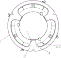
FIG. 1 is a bottom view of a first support housing according to an embodiment of the present invention;
FIG. 2 is a side view of a first support housing according to an embodiment of the present invention;
FIG. 3 is an enlarged view of a portion of FIG. 2;
FIG. 4 is a bottom view of the second support housing according to the embodiment of the present invention;
FIG. 5 is a top view of a second support housing according to an embodiment of the present invention;
FIG. 6 is a side view of a second support housing according to an embodiment of the present invention;
FIG. 7 is a schematic node diagram of point III shown in FIG. 6;
FIG. 8 is a second perspective side view of the second support housing in accordance with the present invention;
FIG. 9 is a schematic node diagram of point II shown in FIG. 8;
FIG. 10 is a third perspective side view of the second support housing in accordance with the present invention;
FIG. 11 is a schematic node diagram of point IV shown in FIG. 10;
fig. 12 is a side view of the third housing according to the embodiment of the invention;
FIG. 13 is a schematic diagram of a second-view side view of the third housing according to the embodiment of the invention;
FIG. 14 is a schematic side view of a third housing according to the embodiment of the invention;
FIG. 15 is a schematic side view of a fourth housing according to the embodiment of the present invention;
FIG. 16 is a top view of a second embodiment of the second support housing of the present invention;
FIG. 17 is a side view of a second embodiment of the third housing of the present invention;
description of reference numerals:
1-a first support shell, 2-a first support part, 3-a first support column, 4-a second support column, 5-a first limiting rib, 6-a first connecting hole, 7-a second support shell, 8-a guide wall, 9-a first connecting part, 10-a second support part, 11-a second connecting hole, 12-a third connecting hole, 13-a stiffening rib device, 14-a first wind deflector, 15-a first through hole, 16-a second limiting rib, 17-a reinforcing rib, 18-a third limiting rib, 19-a first clamping plate, 20-a second clamping plate, 21-a boss, 22-a first screw column, 23-a first limiting plate, 24-a second limiting plate, 25-a wind deflector port, 26-a notch, 27-a first positioning device, 28-a clamping block, 29-a first positioning plate, 30-a second positioning plate, 31-a third shell, 32-a third shell main body, 33-an air outlet, 34-a second air deflector, 35-a second positioning device, 36-a third positioning device, 37-a fourth limiting rib, 38-a second screw column, 39-a clamping wire hoop, 40-a first connecting plate, 41-a third screw column, 42-a third limiting plate, 43-a fourth limiting plate, 44-a clamping hook, 45-a first supporting plate, 46-a first inserting groove, 47-a lug, 48-a fourth shell, 49-a second supporting plate, 50-a third supporting plate, 51-a second accommodating part, 52-a fifth limiting plate, 53-an inserting block, 54-a limiting groove and 55-a bottom plate, 56-first seal, 57-second seal.
Detailed Description
It should be noted that the embodiments and features of the embodiments may be combined with each other without conflict.
It should be noted that all directional indicators (such as up, down, left, right, front, and back) in the embodiments of the present invention are only used to explain the relative position relationship between the components, the motion situation, and the like in a specific posture (as shown in the drawings), and if the specific posture is changed, the directional indicator is changed accordingly.
In addition, the descriptions related to "first", "second", etc. in the present invention are for descriptive purposes only and are not to be construed as indicating or implying relative importance or implicitly indicating the number of technical features indicated. In addition, the technical solutions in the embodiments may be combined with each other, but it is necessary that a person skilled in the art can realize the combination, and the technical solutions in the embodiments are within the protection scope of the present invention.
The present invention will be described in detail below with reference to the embodiments with reference to the attached drawings.
Embodiment 1, as shown in fig. 1 to 9, the present invention discloses a support structure of an airflow controller, including a first support housing 1 and a second support housing 7, where the second support housing 7 is disposed below the first support housing 1, a first support portion 2 is disposed on the first support housing 1, a support column device is disposed on the first support portion 2, the second support housing 7 includes a guide wall 8, a first connection portion 9 is disposed on the guide wall 8, a second support portion 10 is disposed on the other side of the first connection portion 9, the support column device is configured to support and fix the second support portion 10, a first accommodation cavity is formed between the first support portion 2 and the second support portion 10, and the second support portion 10 fixes the airflow controller on a side far from the first support portion 2.
According to the supporting structure of the airflow controller, the first accommodating cavity is formed by the first supporting shell and the second supporting shell which are arranged at the upper layer and the lower layer, the space structure is reasonably utilized, the size of the supporting structure is reduced, the strength of the supporting structure and the connection stability of the first supporting shell and the second supporting shell are ensured through the supporting column device arranged on the first supporting part, the problem that the connection of the airflow controller is unstable due to vibration and the like in use is avoided, and therefore the supporting reliability and stability are improved.
Preferably, as a preferred embodiment of the present invention, a first limiting rib 5 is disposed on the first supporting portion 2, the supporting column device is disposed on one side of the first limiting rib 5, the supporting column device includes a plurality of supporting columns, and the height of the supporting columns is higher than the height of the first limiting rib 5. The height of the supporting column is higher than that of the first limiting rib, so that air flow can enter and exit conveniently.
As an example of the present invention, the supporting column device includes a first supporting column 3 and a second supporting column 4, a second connecting hole 11 and a third connecting hole 12 are provided on a second supporting portion 10, the first supporting column 3 is detachably connected to the third connecting hole 12, and the second supporting column 4 is detachably connected to the second connecting hole 11. Specifically, first connecting hole 6 is formed in first supporting column 3 and second supporting column 4, and first connecting hole 6 is used for being in bolted connection with second connecting hole 11 and third connecting hole 12. This setting discloses a concrete structure of support column device, guarantees convenience and stability that first support housing and second support housing are connected.
Further, as a preferred embodiment of the present invention, a boss 21 is disposed on the periphery of the second connection hole 11 and the third connection hole 12, and the boss 21 is disposed on the second support portion 10 at a side close to the first support housing 1. This arrangement further ensures the reliability of the connection of the first support housing with the second support housing.
Preferably, as a preferred embodiment of the present invention, a first through hole 15 is provided on the second supporting portion 10, and the first through hole 15 is communicated with the first accommodating chamber. The arrangement facilitates the accommodation and the limitation of partial structures of airflow controllers of different models, and improves the applicability of the invention.
Further, as a preferred embodiment of the present invention, a card device is disposed on the second supporting portion 10, and the card device is disposed on a side of the second supporting portion 10 away from the first wind deflector 14. As some examples of the present invention, the card device includes a first card 19 and a second card 20, and the card device is used for limiting the electric control circuit inside the indoor unit, so as to avoid disorder of the electric control circuit.
Preferably, as a preferred embodiment of the present invention, a stiffening rib device 13 is disposed on the second support portion 10, and the stiffening rib device 13 is disposed on a side of the second support portion 10 away from the first support portion 2. As some examples of the present invention, the stiffening rib device 13 includes a plurality of stiffening ribs, and a stiffening rib is also disposed at the connection position of the second supporting portion 10 and the first connecting portion 9, which on one hand enhances the strength of the second supporting portion and on the other hand facilitates the limiting of the electric control circuit of the airflow controller.
Further, as a preferred embodiment of the present invention, a second limiting rib 16 is disposed on the second supporting portion 10, the second limiting rib 16 is disposed on a side close to the first supporting portion 2, and the second limiting rib 16 is connected with the first limiting rib 5 in a sleeved contact manner. As some examples of the present invention, the upper plane of the first air deflector 14 is supported in contact with the first limiting rib 5, and this arrangement discloses a positioning manner of the second supporting portion 10 and the first supporting portion 2, which further improves the rapidity and stability of assembling the first supporting housing and the second supporting housing.
Preferably, as a preferred embodiment of the present invention, a third limiting rib 18 is disposed on the first connecting portion 9, the third limiting rib 18 is disposed on a side close to the first supporting portion 2, and an upper plane of the second supporting portion 10, an upper plane of the first air deflector 14, and an upper plane of the third limiting rib 18 are disposed in a step shape. This setting has guaranteed the convenience of first support casing and the assembly of second support casing on the one hand, and on the other hand has also improved the reliability that air flow controller controlled the air current business turn over.
Further, as a preferred embodiment of the present invention, a reinforcing rib 17 is provided on the upper plane of the first air guiding plate 14. The arrangement further improves the strength of the first air deflector 14, and the first air deflector 14 is prevented from deforming in the use process.
The invention also discloses an air conditioner which comprises the supporting structure of the airflow controller.
The air guide structure of the air flow controller is formed by detachably connecting the first support shell and the second support shell in a matched mode, and an air guide path is formed by detachably and fixedly connecting an upper air guide structure arranged on the second support shell and a lower air guide structure arranged on the third shell on one side of the air flow controller.
Preferably, as a preferred embodiment of the present invention, the upper air guiding structure includes a first air guiding plate 14, a first limiting plate 23, and a second limiting plate 24, the first limiting plate 23 and the second limiting plate 24 are disposed on a lower surface of the first air guiding plate 14, a height of the lower surface of the first air guiding plate 14 is higher than a height of the lower surface of the second supporting portion 10, one end of the first limiting plate 23 and one end of the second limiting plate 24 contact with the second supporting portion 10, and the heights of the lower surfaces of the first limiting plate 23 and the second limiting plate 24 are lower than the height of the lower surface of the second supporting portion 10. This setting discloses a concrete structure of going up wind-guiding structure, is step-like setting through being first aviation baffle 14 with second supporting part 10, is convenient for accomodate the air current of air flow controller exhaust with first limiting plate 23, the cooperation of second limiting plate 24, all is less than the setting of second supporting part 10 lower surface height with the height of first limiting plate 23 lower surface, the height of second limiting plate 24 lower surface, is convenient for improve the wind-guiding effect in wind-guiding route.
Further, as a preferred embodiment of the present invention, the first limiting plate 23 and the second limiting plate 24 are disposed in an arc shape, an end of the first limiting plate 23 at an end far away from the second supporting portion 10 is spaced apart from an end of the first air deflector 14, and a notch 26 is disposed on the first limiting plate 23. The arrangement forms an air guide opening 25 at the end part of the first air guide plate far away from the second supporting part, and the guide and the discharge of air flow are facilitated through the notch arranged on the first limiting plate 23.
Preferably, as a preferred embodiment of the present invention, the lower air guiding structure includes a second air guiding plate 34, a third limiting plate 42 and a fourth limiting plate 43 are disposed on an upper surface of the second air guiding plate 34, the third limiting plate 42 and the fourth limiting plate 43 are all fixedly connected to the third casing main body 32, the third limiting plate 42 is detachably and fixedly connected to the second limiting plate 24, and the fourth limiting plate 43 is detachably and fixedly connected to the first limiting plate 23. This setting discloses a concrete structure of wind-guiding structure down, and through the third limiting plate 42, second limiting plate 24, fourth limiting plate 43, first limiting plate 23 and first aviation baffle 14, the second aviation baffle 34 that will cooperate the connection form the wind-guiding route, be convenient for to the air current controller exhaust air current and lead the circulation.
Further, as a preferred embodiment of the present invention, a latch 28 is disposed on the second stopper plate 24, a hook 44 is disposed on the third stopper plate 42, the hook 44 is connected to the latch 28 in a snap-fit manner, a first positioning device 27 is disposed at an end of the first stopper plate 23 close to the second supporting portion 10, a third positioning device 36 is disposed at an end of the fourth stopper plate 43 far from the third housing main body 32, and the third positioning device 36 is connected to the first positioning device 27 in a limiting manner. As some examples of the present invention, a second positioning device 35 is provided at an end of the third stopper plate 42 on the side away from the third casing main body 32, and the second positioning device 35 cooperates to stop an end of the second stopper plate 24. This setting discloses a concrete mode of going up wind-guiding structure and wind-guiding structure assembly down, convenient and fast connects stably.
Preferably, as a preferred embodiment of the present invention, the first positioning device 27 includes a first positioning plate 29 and a second positioning plate 30, the first positioning plate 29 and the second positioning plate 30 are disposed in a bent shape, and the second positioning plate 30 is disposed on a lower surface of the second supporting portion 10. This setting discloses a concrete structure of first positioner, has guaranteed the convenience and the reliability of first positioner and third positioner location assembly.
Further, as a preferred embodiment of the present invention, a fourth limiting rib 37 is disposed on a lower surface of the second air deflector 34, the fourth limiting rib 37 is disposed in a closed shape, the fourth limiting rib 37 is used for supporting and positioning an electric control board, a second screw column 38 is disposed inside the fourth limiting rib 37, the second screw column 38 is disposed on the second air deflector 34, and the second screw column 38 is used for fixing with the electric control board. This setting rational utilization spatial structure improves the inside space utilization of air conditioner.
Preferably, as a preferred embodiment of the present invention, a first connection plate 40 is disposed on a side of the third limiting plate 42 away from the fourth limiting plate 43, a third screw column 41 is disposed on the first connection plate 40, and the third screw column 41 is detachably connected to the first screw column 22 disposed on the first supporting housing 1. As an example of the present invention, the third screw column 41 is provided in plurality on the third housing 31, and the first screw column 22 is provided in plurality on the first support housing 1, and this arrangement ensures the stability of the fitting connection of the first support housing 1, the second support housing 7, and the third housing 31.
Further, a wire clamping hoop 39 is arranged on the side of the third limiting plate 42 away from the fourth limiting plate 43, and the wire clamping hoop 39 is arranged between the second positioning device 35 and the first connecting plate 40. The setting avoids disorder of an electric control circuit, and ensures the use reliability of the air conditioner and the airflow controller.
The invention also discloses an air conditioner, which comprises the air guide structure of the airflow controller.
The fixing device of the air flow controller forms a supporting structure of the air flow controller by matching the first supporting shell and the second supporting shell which are arranged at the upper layer and the lower layer, forms an air flow controller accommodating device by detachably connecting the third shell and the fourth shell, and forms an air flow controller accommodating cavity by matching the air flow controller accommodating device with the second supporting part, so that the air flow controller is supported, accommodated and positioned, the supporting and fixing safety and the use reliability of the air flow controller are ensured, the air guide flow of the air flow controller is prevented from overflowing, the air flow controller changes the flow direction of discharged air by the air guide structure communicated with the air flow controller accommodating cavity, the guide direction of the air flow controller is conveniently diversified, and the air outlet effect of the air conditioner is ensured.
The fixing device of the airflow controller is reasonable in structure and stable in connection, and ensures the connection stability and the use reliability of the airflow controller.
Preferably, as a preferred embodiment of the present invention, the fourth casing 48 includes a second supporting plate 49 and a third supporting plate 50, the second supporting plate 49 and the third supporting plate 50 are arranged in a step shape, the third casing 31 includes a third casing main body 32, the second supporting plate 49 and the third supporting plate 50 are fixed to the lower end of the third casing main body 32 in a contact manner, the fourth casing 48 is detachably connected to the third casing 31, a second accommodating portion 51 is arranged on the third supporting plate 50, the second accommodating portion 51 passes through a lower air guiding structure arranged on the third casing 31, and the second accommodating portion 51 is limited by an end of the lower air guiding structure. This setting discloses an airflow controller accommodate device's formation structure, through passing the second portion of holding the lower wind-guiding structure that sets up on the third casing, the second portion of holding is carried out spacing setting by the tip of wind-guiding structure down, has guaranteed the stability and the reliability of airflow controller accommodate device and wind-guiding structure assembly.
Further, as a preferred embodiment of the present invention, the second accommodating portion 51 includes a bottom plate 55, a fifth limiting plate 52 is disposed on the bottom plate 55, the fifth limiting plate 52 is disposed along an edge of the bottom plate 55, a limiting groove 54 is disposed on the fifth limiting plate 52, and the limiting groove 54 is in limiting connection with the lower wind guiding structure. Specifically, the second air deflector 34 is clamped in the limiting groove 54, and two ends of the limiting groove 54 are in contact with the third limiting plate 42 and the fourth limiting plate 43 for limiting respectively.
Preferably, as a preferred embodiment of the present invention, the lower air guiding structure includes a second air guiding plate 34, a third limiting plate 42 and a fourth limiting plate 43 are disposed on an upper surface of the second air guiding plate 34, the third limiting plate 42 and the fourth limiting plate 43 are all fixedly connected to the third casing main body 32, a second positioning device 35 and a third positioning device 36 are disposed at an end of the second air guiding plate 34 away from the third casing main body 32, and the second positioning device 35 and the third positioning device 36 are used for limiting the fifth limiting plate 52. This setting discloses a lower wind-guiding structure, and is spacing to the fifth limiting plate through the second positioner, the third positioner that set up under wind-guiding structure, further guaranteed the fourth casing with third casing assembly connection's stability avoids air flow controller accommodate device to take place to rock or the displacement in the use, influences air flow controller's normal use.
Further, the second positioning device 35 is disposed on the third limiting plate 42 and away from one side of the fourth limiting plate 43, the second positioning device 35 is disposed in a vertical bent shape, the third positioning device 36 is disposed on the fourth limiting plate 43 and away from one side of the third limiting plate 42, and the third positioning device 36 is disposed in a vertical bent shape. This setting discloses a second positioner and third positioner's concrete structure, the production of being convenient for to it is right to improve second positioner, third positioner the spacing reliability of fifth limiting plate.
Preferably, as a preferred embodiment of the present invention, a first supporting plate 45 is disposed on the third casing main body 32, the first supporting plate 45 is disposed on the lower surface of the second wind deflector 34, a first inserting groove 46 is formed among the third positioning device 36, the fourth limiting plate 43 and the first supporting plate 45, an inserting block 53 is disposed on the second accommodating portion 51, and the inserting block 53 is inserted into the first inserting groove 46 for limiting. This setting has further improved the stability that fourth casing is connected with the third casing and the convenience of assembly.
Further, the insertion block 53 is in a trapezoid shape, and the width of the end of the insertion block 53 close to the bottom plate 55 is greater than the width of the end of the insertion block 53 far from the bottom plate 55. The arrangement further improves the convenience and reliability of the plug-in connection of the plug-in block and the first plug-in groove.
Preferably, a bump 47 is arranged on the second air deflector 34, the bump 47 is arranged on the lower surface of the end of the second air deflector 34, and the bump 47 is used for performing contact connection on the bottom end of the limiting groove 54. The strength of the end part of the second air deflector is enhanced, and the situation that the lower air guide structure is deformed when being connected with the limiting groove to influence the connection stability of the fourth shell and the third shell is avoided.
Further, the air outlet 33 is disposed above a contact portion of the second air deflector 34 and the third casing body, and the air outlet 33 is disposed in a grid shape. This setting has further improved airflow controller's air-out effect, improves user experience's comfort level.
The invention also discloses an air conditioner, which comprises the fixing device of the airflow controller.
The invention discloses an airflow sealing device, which is characterized in that a first supporting shell and a second supporting shell are matched to form a supporting structure of an airflow controller, a first accommodating cavity is formed by the first supporting shell and the second supporting shell which are arranged in an upper layer and a lower layer, a space structure is reasonably utilized, the volume of the supporting structure is reduced, a first sealing element arranged in the first accommodating cavity seals the joint of the outer walls of the first supporting shell and the second supporting shell, the phenomenon that airflow discharged by the airflow controller is scattered outwards along the joint of the outer walls of the first supporting shell and the second supporting shell to affect the exhaust effect of the airflow controller is avoided, the disordered airflow brings discomfort to a user, and the experience effect of the user is reduced.
Preferably, as a preferred embodiment of the present invention, a plurality of first connecting portions 9 are provided on the guide wall 8, a first sealing member 56 is provided on each first connecting portion 9, and the first sealing member 56 protrudes from both sides of the first connecting portion 9 at one end near the guide wall 8. As some examples of the invention, the first connecting parts 9 are uniformly distributed on the guide wall 8, preferably 3-5, and the arrangement improves the stability and reliability of the air outlet of the air conditioner and avoids generating turbulent flow.
Further, as a preferred embodiment of the present invention, the first sealing member 56 is made of a sealing sponge, and the first sealing member 56 is adhered to the upper surface of the first connecting portion 9. This set up material and the connected mode of disclosing a first sealing member 56, the first sealing member 56 of making through sealed sponge is convenient for carry out the shape change according to the structural change of first connecting portion 9 and guide wall 8, guarantees first support housing and second support housing's outer wall junction sealing connection's reliability.
Preferably, as a preferred embodiment of the present invention, an upper wind guiding structure is disposed on one side of the second supporting portion 10, a third casing 31 is disposed below the second supporting casing 7, a lower wind guiding structure is disposed on the third casing 31, the upper wind guiding structure and the lower wind guiding structure are detachably connected, a wind guiding path is formed between the upper wind guiding structure and the lower wind guiding structure, the other end of the wind guiding path is communicated with a wind outlet 33, and the wind outlet 33 is disposed on the third casing main body 32. This setting is convenient for carry out diversified setting with air flow controller's water conservancy diversion direction, guarantees the air-out effect of air conditioner.
Further, as a preferred embodiment of the present invention, the upper air guiding structure includes a first air guiding plate 14, a first limiting plate 23, and a second limiting plate 24, the first limiting plate 23, and the second limiting plate 24 are disposed on a lower surface of the first air guiding plate 14, the lower air guiding structure includes a second air guiding plate 34, a third limiting plate 42, and a fourth limiting plate 43 are disposed on an upper surface of the second air guiding plate 34, the third limiting plate 42, and the fourth limiting plate 43 are all fixedly connected to the third casing main body 32, the third limiting plate 42 is detachably and fixedly connected to the second limiting plate 24, and the fourth limiting plate 43 is detachably and fixedly connected to the first limiting plate 23. This setting discloses a concrete structure of wind-guiding route, and the assembly is convenient, the processing preparation of being convenient for.
Preferably, as a preferred embodiment of the present invention, the second air deflector 34, the third limiting plate 42, and the fourth limiting plate 43 form an air induction opening with the first air deflector 14, the first limiting plate 23, and the second limiting plate 24 at an end portion far away from the third casing main body 32, the air induction opening is detachably connected with an air outlet of the airflow controller, a second sealing element 57 is disposed at the air induction opening, and the second sealing element 57 is used for sealing connection between the air induction opening and the airflow controller. The arrangement further avoids the exhaust air flow of the air flow controller from scattering and overflowing at the joint of the air flow controller and the air guide path to influence the air guide effect.
Further, as a preferred embodiment of the present invention, the second sealing member 57 is made of a sealing sponge, and the second sealing member 57 is adhered to the upper surface of the second air deflector 34. This arrangement discloses a material and a connection method of the second sealing member 57, and the second sealing member 57 is disposed inside the air introducing opening, thereby further improving the sealing property at the connection between the air flow controller and the air guide path.
Preferably, as a preferred embodiment of the present invention, the height of the lower surface of the first air deflector 14 is higher than the height of the lower surface of the second support portion 10, one end of the first limiting plate 23 and one end of the second limiting plate 24 contact with the second support portion 10, and the heights of the lower surfaces of the first limiting plate 23 and the second limiting plate 24 are lower than the height of the lower surface of the second support portion 10. This setting is through being step-like setting with first aviation baffle 14 and second supporting part 10, be convenient for accomodate the air current of air flow controller combustion gas with first limiting plate 23, second limiting plate 24 complex, all is less than the setting of second supporting part 10 lower surface height with the height of first limiting plate 23 lower surface, the height of second limiting plate 24 lower surface, is convenient for improve the wind-guiding effect in wind-guiding route to and be convenient for go up wind-guiding structure and wind-guiding structure assembly down.
Further, as a preferred embodiment of the present invention, the upper air guiding structure and the lower air guiding structure are arranged in an arc shape, and a notch 26 is arranged on the first limiting plate 23. This arrangement further improves the directing and discharging effect of the air flow controller to control the air flow.
The invention also discloses an air conditioner which comprises the airflow sealing device.
Embodiment 5, as shown in fig. 1 to 17, the present invention further discloses an assembly structure of an airflow controller and an air conditioner, including a first support housing 1, a second support housing 7, a third housing 31, and a fourth housing 48, which are sequentially arranged from top to bottom, wherein the first support housing 1 and the second support housing 7 are detachably connected to form a support device, the support device is used to fix and support a top of the airflow controller, the third housing 31 and the fourth housing 48 are detachably connected to form an accommodating device, the accommodating device and the support device are assembled to form a fixing device of the airflow controller, the first support portion 2 is arranged on the first support housing 1, the second support housing 7 is arranged on the second support housing 10, the first support portion 2 and the second support portion 10 form a first accommodating cavity, the airflow controller is used to change the direction of the gas accommodated in the first accommodating cavity, other configurations are as in the other embodiments.
Preferably, as a preferred embodiment of the present invention, a first support part 2 is provided on the first support housing 1, a support post device is provided on the first support part 2, a second support part 10 is provided on the second support housing 7, and the support post device is detachably connected to the second support part 10. This setting discloses a formation structure of first chamber of holding, and the installation of being convenient for connects stably.
Further, as a preferred embodiment of the present invention, a first limiting rib 5 is disposed on the first supporting portion 2, a second limiting rib 16 is disposed on the second supporting portion 10, the second limiting rib 16 is disposed at a side close to the first supporting portion 2, and the second limiting rib 16 is connected to the first limiting rib 5 in a sleeved contact manner. This setting discloses one kind first support housing 1 with the limit structure of second support housing 7, the assembly of being convenient for, it is spacing reliable.
Preferably, as a preferred embodiment of the present invention, the supporting column device includes a plurality of supporting columns, and the height of the supporting columns is higher than the height of the first limiting rib 5. This setting will the height of support column is higher than the height of first spacing muscle, the circulation of the air current of being convenient for.
Further, as a preferred embodiment of the present invention, a first through hole 15 is disposed on the second supporting portion 10, the first through hole 15 is communicated with the first accommodating cavity, the second supporting portion 10 is used for supporting and fixing an air flow controller, an upper air guiding structure is disposed on one side of the second supporting portion 10, a lower air guiding structure is disposed on the third casing 31, the upper air guiding structure and the lower air guiding structure form an air guiding path, the first through hole 15 is communicated with the air guiding path through the air flow controller, the other end of the air guiding path is communicated with an air outlet 33, and the air outlet 33 is disposed on the third casing main body 32. This arrangement discloses a diversion path for the airflow control to facilitate further regulation and control of the exhaust airflow.
Preferably, as a preferred embodiment of the present invention, the upper air guiding structure includes a first air guiding plate 14, a first limiting plate 23, and a second limiting plate 24, the lower air guiding structure includes a second air guiding plate 34, a third limiting plate 42 and a fourth limiting plate 43 are disposed on an upper surface of the second air guiding plate 34, the third limiting plate 42 is detachably and fixedly connected to the second limiting plate 24, and the fourth limiting plate 43 is detachably and fixedly connected to the first limiting plate 23. This setting discloses a concrete structure of wind-guiding route, and the assembly and the fixing of wind-guiding structure and lower wind-guiding structure are convenient for, convenient and fast connects stably.
Further, as a preferred embodiment of the present invention, the height of the lower surface of the first wind deflector 14 is higher than the height of the lower surface of the second supporting portion 10, and the height of the upper surface of the second wind deflector 34 is lower than the height of the lower surface of the second supporting portion 10. This setting is convenient for improve the size in wind-guiding route, and rational utilization inner space strengthens the wind-guiding effect.
Preferably, as a preferred embodiment of the present invention, the third casing 31 and the fourth casing 48 are assembled to form an airflow controller accommodating device, the third casing 31 includes a third casing main body 32, the fourth casing 48 includes a second supporting plate 49 and a third supporting plate 50, the second supporting plate 49 and the third supporting plate 50 are fixed in contact with a lower end of the third casing main body 32, the fourth casing 48 is detachably connected to the third casing 31, a second accommodating portion 51 is disposed on the third supporting plate 50, the second accommodating portion 51 passes through a lower air guiding structure disposed on the third casing 31, and the second accommodating portion 51 is limited by an end of the lower air guiding structure. This setting discloses a concrete air flow controller accommodate device, is convenient for processing and assembly, improves production efficiency.
Further, as a preferred embodiment of the present invention, a gasket is disposed on a lower surface of the second supporting portion 10. This setting has guaranteed airflow controller's water conservancy diversion effect and shock attenuation effect, avoids the too big travelling comfort that influences the user and use of noise.
The invention also discloses an air conditioner, which comprises the assembly structure of the airflow controller.
The invention also discloses an assembly method of the air conditioner, the air conditioner comprises the assembly structure of the airflow controller, and the method comprises the following specific steps:
ST1, corresponding the support column device to the connecting hole device, detachably connecting the first support shell 1 and the second support shell 7 through screws, and forming a first accommodating cavity between the first support shell 1 and the second support shell 7;
specifically, the first support housing 1 is fixedly connected with a drainage structure of the air conditioner, a support column device arranged at the position of the first support part 2 on the first support housing 1 is in screw connection with a connecting hole device arranged at the position of the second support part 10 on the second support housing 7, and a plurality of support column devices are in screw connection with a plurality of connecting hole devices in a matched manner.
ST 2: a fan of the airflow controller corresponds to the first through hole 15 on the second supporting part 10, and the airflow controller is fixed on the lower surface of the second supporting part 10 through a screw to form an airflow controller supporting device;
specifically, the support column device that sets up on first support portion 2 includes first support column 3, second support column 4, first support column 3 set up first connecting hole 6 on second support column 4, set up second connecting hole 11, third connecting hole 12 on second support portion 10, the airflow controller passes second connecting hole 11, third connecting hole 12 respectively through a plurality of screws and is connected with 6 screw connections of first connecting hole on the support column device. This setting passes through the screw and realizes that air flow controller, first support casing 1 and second support casing 7's fixed connection, has reduced the setting of spare part, guarantees the stability that air flow controller, first support casing 1 and second support casing 7 are connected.
ST 3: the fourth shell 48 is buckled and pressed on the third shell 31 through external force, and the third shell 31 and the fourth shell 48 are assembled in an inserting mode to form the airflow controller accommodating device;
specifically, the fourth casing 48 includes a second support plate 49 and a third support plate 50 which are arranged in a step shape, a second accommodating portion 51 is arranged on the third support plate 50, the second accommodating portion 51 passes through a lower air guide structure arranged on the third casing 31, the second accommodating portion 51 includes a bottom plate 55, a fifth limiting plate 52 is arranged on the bottom plate 55, a limiting groove 54 is arranged on the fifth limiting plate 52, the second air guide plate 34 on the third casing 31 is clamped into the limiting groove 54, a first inserting groove 46 is formed between the upper and lower air guide structure of the third casing main body 32 and the first support plate 45, an inserting block 53 is arranged on the second accommodating portion 51, and the inserting block 53 is inserted into the first inserting groove 46 for limiting, so that the third casing 31 and the fourth casing 48 are fixed in an inserting manner.
ST4, the air flow controller containing device formed by assembly corresponds to the air flow controller, and the upper air guide structure on the second supporting shell 7 is clamped with the upper air guide structure and the lower air guide structure of the third shell 31 for preliminary positioning and fixing;
ST 5: and fixing the assembled airflow controller accommodating device and the airflow controller supporting device for the second time through screws.
The assembly method can simplify the installation steps, the first supporting shell 1 and the second supporting shell 7 are matched and positioned, the first connecting hole 6 on the first supporting shell 1, the connecting hole device on the second supporting shell 7 and the connecting hole of the airflow controller are correspondingly arranged, so that the first supporting shell 1, the second supporting shell 7 and the three connecting holes on the airflow controller are simultaneously connected through one screw, the use of parts is reduced, the fixing of the airflow controller is realized, the third shell 31 and the fourth shell 48 are inserted and assembled to form the airflow controller accommodating device, when the airflow controller accommodating device and the airflow controller supporting device are fixed, the upper air guide structure on the second supporting shell 7 is firstly clamped with the upper and lower air guide structures of the third shell 31 to carry out primary positioning and fixing, and then the secondary fixing of the airflow controller accommodating device and the airflow controller supporting device is realized through screw connection, the steps of directly fixing the second supporting shell 7 and the third shell 31 are reduced, the stability of connection of the assembly structure of the airflow controller is ensured, and the assembly and disassembly are convenient.
The above description is only for the purpose of illustrating the preferred embodiments of the present invention and is not to be construed as limiting the invention, and any modifications, equivalents, improvements and the like that fall within the spirit and principle of the present invention are intended to be included therein.
Claims (10)
1. The assembly structure of the airflow controller is characterized by comprising a first supporting shell (1), a second supporting shell (7), a third shell (31) and a fourth shell (48) which are sequentially arranged from top to bottom, wherein the first supporting shell (1) and the second supporting shell (7) are detachably connected to form an airflow controller supporting device, the airflow controller supporting device is used for fixedly supporting the top of the airflow controller, the third shell (31) and the fourth shell (48) are detachably connected to form an airflow controller accommodating device, the airflow controller accommodating device and the airflow controller supporting device are assembled to form a fixing device of the airflow controller, a first supporting part (2) is arranged on the first supporting shell (1), a second supporting part (10) is arranged on the second supporting shell (7), and a first accommodating cavity is formed between the first supporting part (2) and the second supporting part (10), the gas flow controller is used for changing the direction of the gas in the first accommodating cavity.
2. An assembling structure of an air flow controller according to claim 1, wherein a support post means is provided on said first support part (2), said support post means being detachably connected to said second support part (10).
3. An assembling structure of an airflow controller according to claim 2, characterized in that a first limiting rib (5) is arranged on the first supporting part (2), a second limiting rib (16) is arranged on the second supporting part (10), the second limiting rib (16) is arranged at one side close to the first supporting part (2), and the second limiting rib (16) is in sleeve contact connection with the first limiting rib (5).
4. An assembling structure of an air flow controller according to claim 3, wherein said supporting column means comprises a plurality of supporting columns, and the height of said supporting columns is higher than the height of said first position-limiting rib (5).
5. The structure of claim 4, wherein a first through hole (15) is formed in the second support portion (10), the first through hole (15) is communicated with the first accommodating cavity, the second support portion (10) is used for supporting and fixing the air flow controller, an upper air guide structure is arranged on one side of the second support portion (10), a lower air guide structure is arranged on the third casing (31), the upper air guide structure and the lower air guide structure form an air guide path, the first through hole (15) is communicated with the air guide path through the air flow controller, the other end of the air guide path is communicated with the air outlet (33), and the air outlet (33) is formed in the third casing body (32).
6. The assembling structure of the airflow controller according to claim 5, wherein the upper air guiding structure comprises a first air guiding plate (14), a first limiting plate (23) and a second limiting plate (24), the lower air guiding structure comprises a second air guiding plate (34), a third limiting plate (42) and a fourth limiting plate (43) are arranged on the upper surface of the second air guiding plate (34), the third limiting plate (42) and the second limiting plate (24) are detachably and fixedly connected, and the fourth limiting plate (43) and the first limiting plate (23) are detachably and fixedly connected.
7. The mounting structure of an airflow controller according to claim 6, wherein the height of the lower surface of the first air deflector (14) is higher than that of the lower surface of the second support portion (10), and the height of the upper surface of the second air deflector (34) is lower than that of the lower surface of the second support portion (10).
8. An assembling structure of an air flow controller according to claim 7, wherein the third housing (31) comprises a third housing main body (32), the fourth housing (48) comprises a second supporting plate (49) and a third supporting plate (50), the second supporting plate (49) and the third supporting plate (50) are fixed in contact with the lower end of the third housing main body (32), the fourth housing (48) is detachably connected with the third housing (31), a second accommodating part (51) is arranged on the third supporting plate (50), the second accommodating part (51) passes through a lower air guiding structure arranged on the third housing (31), and the second accommodating part (51) is limited by the end of the lower air guiding structure.
9. An assembling structure of an air flow controller according to claim 5, 7 or 8, wherein a packing is provided on a lower surface of said second supporting portion (10).
10. An air conditioner, characterized in that: an assembly structure comprising an air flow controller as claimed in any one of claims 1 to 9.
Priority Applications (1)
| Application Number | Priority Date | Filing Date | Title |
|---|---|---|---|
| CN201811347373.0A CN111174392B (en) | 2018-11-13 | 2018-11-13 | Assembly structure and assembly method of airflow controller and air conditioner |
Applications Claiming Priority (1)
| Application Number | Priority Date | Filing Date | Title |
|---|---|---|---|
| CN201811347373.0A CN111174392B (en) | 2018-11-13 | 2018-11-13 | Assembly structure and assembly method of airflow controller and air conditioner |
Publications (2)
| Publication Number | Publication Date |
|---|---|
| CN111174392A true CN111174392A (en) | 2020-05-19 |
| CN111174392B CN111174392B (en) | 2021-06-01 |
Family
ID=70655743
Family Applications (1)
| Application Number | Title | Priority Date | Filing Date |
|---|---|---|---|
| CN201811347373.0A Active CN111174392B (en) | 2018-11-13 | 2018-11-13 | Assembly structure and assembly method of airflow controller and air conditioner |
Country Status (1)
| Country | Link |
|---|---|
| CN (1) | CN111174392B (en) |
Citations (12)
| Publication number | Priority date | Publication date | Assignee | Title |
|---|---|---|---|---|
| JPH08178345A (en) * | 1994-12-22 | 1996-07-12 | Toshiba Corp | Ceiling cassette type air-conditioner |
| US5833530A (en) * | 1997-03-19 | 1998-11-10 | Kuo; Jin-Yu | Electricity-Free rotary wind blowing apparatus |
| CN200979255Y (en) * | 2006-11-29 | 2007-11-21 | 管印贵 | Four-air-outlet air-handling unit |
| CN101122407A (en) * | 2006-08-10 | 2008-02-13 | Lg电子株式会社 | Air conditioner |
| CN201844518U (en) * | 2010-11-12 | 2011-05-25 | 四川长虹空调有限公司 | Embedded air-condition indoor unit with diversion structure |
| CN203274153U (en) * | 2013-06-03 | 2013-11-06 | 海尔集团公司 | Air-conditioning air supply device with airflow distribution component |
| CN204880611U (en) * | 2015-08-10 | 2015-12-16 | Tcl空调器(中山)有限公司 | Air ducting, air -out device and air conditioner |
| CN205939611U (en) * | 2016-08-09 | 2017-02-08 | 珠海格力电器股份有限公司 | Air -out mechanism and air conditioner |
| CN106766071A (en) * | 2016-11-24 | 2017-05-31 | 广东美的制冷设备有限公司 | Panel assembly and air-conditioner |
| CN207132473U (en) * | 2017-09-11 | 2018-03-23 | 广东美的制冷设备有限公司 | Window air conditioner |
| CN207262551U (en) * | 2017-08-31 | 2018-04-20 | 广东美的制冷设备有限公司 | Ceiling machine |
| CN207350488U (en) * | 2017-06-23 | 2018-05-11 | 大金工业株式会社 | Indoor apparatus of air conditioner |
-
2018
- 2018-11-13 CN CN201811347373.0A patent/CN111174392B/en active Active
Patent Citations (12)
| Publication number | Priority date | Publication date | Assignee | Title |
|---|---|---|---|---|
| JPH08178345A (en) * | 1994-12-22 | 1996-07-12 | Toshiba Corp | Ceiling cassette type air-conditioner |
| US5833530A (en) * | 1997-03-19 | 1998-11-10 | Kuo; Jin-Yu | Electricity-Free rotary wind blowing apparatus |
| CN101122407A (en) * | 2006-08-10 | 2008-02-13 | Lg电子株式会社 | Air conditioner |
| CN200979255Y (en) * | 2006-11-29 | 2007-11-21 | 管印贵 | Four-air-outlet air-handling unit |
| CN201844518U (en) * | 2010-11-12 | 2011-05-25 | 四川长虹空调有限公司 | Embedded air-condition indoor unit with diversion structure |
| CN203274153U (en) * | 2013-06-03 | 2013-11-06 | 海尔集团公司 | Air-conditioning air supply device with airflow distribution component |
| CN204880611U (en) * | 2015-08-10 | 2015-12-16 | Tcl空调器(中山)有限公司 | Air ducting, air -out device and air conditioner |
| CN205939611U (en) * | 2016-08-09 | 2017-02-08 | 珠海格力电器股份有限公司 | Air -out mechanism and air conditioner |
| CN106766071A (en) * | 2016-11-24 | 2017-05-31 | 广东美的制冷设备有限公司 | Panel assembly and air-conditioner |
| CN207350488U (en) * | 2017-06-23 | 2018-05-11 | 大金工业株式会社 | Indoor apparatus of air conditioner |
| CN207262551U (en) * | 2017-08-31 | 2018-04-20 | 广东美的制冷设备有限公司 | Ceiling machine |
| CN207132473U (en) * | 2017-09-11 | 2018-03-23 | 广东美的制冷设备有限公司 | Window air conditioner |
Also Published As
| Publication number | Publication date |
|---|---|
| CN111174392B (en) | 2021-06-01 |
Similar Documents
| Publication | Publication Date | Title |
|---|---|---|
| CN111174392B (en) | Assembly structure and assembly method of airflow controller and air conditioner | |
| CN104633821A (en) | Humidifier | |
| CN213272923U (en) | Integral air conditioner | |
| CN105485778A (en) | Indoor air conditioner | |
| CN105526634B (en) | Axle stream cabinet-type air conditioner | |
| CN204730433U (en) | For the drip tray of air conditioner room unit, air conditioner room unit and air-conditioner | |
| CN209920983U (en) | Evaporating air duct of parking air conditioner | |
| CN101576291A (en) | Outdoor machine of air conditioner | |
| CN209054761U (en) | A kind of air conditioner and air-conditioner control system | |
| CN113692176A (en) | Electrical system | |
| CN106051923B (en) | Wall-mounted air conditioner indoor unit and air conditioner | |
| CN209541123U (en) | A kind of support construction and air conditioner of gas flow controller | |
| CN216481565U (en) | Water collector mounting structure and have its air conditioner | |
| CN112622573B (en) | Air conditioning system and vehicle with same | |
| CN220507151U (en) | Fog baffle and fog outlet assembly | |
| CN217302996U (en) | Air conditioner indoor unit and air conditioner | |
| CN216481554U (en) | Shell assembly structure and air conditioner with same | |
| WO2021093252A1 (en) | Movable air conditioner | |
| CN215062465U (en) | Air duct machine and air conditioner | |
| CN210818743U (en) | CNC machine tool bus transmission controller | |
| CN100432568C (en) | Distributor for central air conditioner | |
| CN219271881U (en) | Humidification device and ventilation treatment equipment | |
| CN219083372U (en) | Heating and ventilation equipment | |
| CN216114396U (en) | Air condensing units and air conditioning system | |
| CN209541023U (en) | A kind of ceiling casing body attachment device and air conditioner |
Legal Events
| Date | Code | Title | Description |
|---|---|---|---|
| PB01 | Publication | ||
| PB01 | Publication | ||
| SE01 | Entry into force of request for substantive examination | ||
| SE01 | Entry into force of request for substantive examination | ||
| GR01 | Patent grant | ||
| GR01 | Patent grant |