CN111173838A - Radial non-coupling three-degree-of-freedom direct-current hybrid magnetic bearing - Google Patents

Radial non-coupling three-degree-of-freedom direct-current hybrid magnetic bearing Download PDF

Info

Publication number
CN111173838A
CN111173838A CN202010055294.3A CN202010055294A CN111173838A CN 111173838 A CN111173838 A CN 111173838A CN 202010055294 A CN202010055294 A CN 202010055294A CN 111173838 A CN111173838 A CN 111173838A
Authority
CN
China
Prior art keywords
radial
iron core
axial
rotor
stator
Prior art date
Legal status (The legal status is an assumption and is not a legal conclusion. Google has not performed a legal analysis and makes no representation as to the accuracy of the status listed.)
Granted
Application number
CN202010055294.3A
Other languages
Chinese (zh)
Other versions
CN111173838B (en
Inventor
朱为国
乐倩云
王紫欣
张涛
叶小婷
鲁庆
莫丽红
武莎莎
Current Assignee (The listed assignees may be inaccurate. Google has not performed a legal analysis and makes no representation or warranty as to the accuracy of the list.)
Hefei Jiuzhou Longteng Scientific And Technological Achievement Transformation Co ltd
Original Assignee
Huaiyin Institute of Technology
Priority date (The priority date is an assumption and is not a legal conclusion. Google has not performed a legal analysis and makes no representation as to the accuracy of the date listed.)
Filing date
Publication date
Application filed by Huaiyin Institute of Technology filed Critical Huaiyin Institute of Technology
Priority to CN202010055294.3A priority Critical patent/CN111173838B/en
Publication of CN111173838A publication Critical patent/CN111173838A/en
Application granted granted Critical
Publication of CN111173838B publication Critical patent/CN111173838B/en
Active legal-status Critical Current
Anticipated expiration legal-status Critical

Links

Images

Classifications

    • FMECHANICAL ENGINEERING; LIGHTING; HEATING; WEAPONS; BLASTING
    • F16ENGINEERING ELEMENTS AND UNITS; GENERAL MEASURES FOR PRODUCING AND MAINTAINING EFFECTIVE FUNCTIONING OF MACHINES OR INSTALLATIONS; THERMAL INSULATION IN GENERAL
    • F16CSHAFTS; FLEXIBLE SHAFTS; ELEMENTS OR CRANKSHAFT MECHANISMS; ROTARY BODIES OTHER THAN GEARING ELEMENTS; BEARINGS
    • F16C32/00Bearings not otherwise provided for
    • F16C32/04Bearings not otherwise provided for using magnetic or electric supporting means
    • F16C32/0406Magnetic bearings
    • F16C32/044Active magnetic bearings
    • F16C32/0474Active magnetic bearings for rotary movement
    • F16C32/0485Active magnetic bearings for rotary movement with active support of three degrees of freedom
    • FMECHANICAL ENGINEERING; LIGHTING; HEATING; WEAPONS; BLASTING
    • F16ENGINEERING ELEMENTS AND UNITS; GENERAL MEASURES FOR PRODUCING AND MAINTAINING EFFECTIVE FUNCTIONING OF MACHINES OR INSTALLATIONS; THERMAL INSULATION IN GENERAL
    • F16CSHAFTS; FLEXIBLE SHAFTS; ELEMENTS OR CRANKSHAFT MECHANISMS; ROTARY BODIES OTHER THAN GEARING ELEMENTS; BEARINGS
    • F16C32/00Bearings not otherwise provided for
    • F16C32/04Bearings not otherwise provided for using magnetic or electric supporting means
    • F16C32/0406Magnetic bearings
    • F16C32/044Active magnetic bearings
    • F16C32/0459Details of the magnetic circuit
    • F16C32/0461Details of the magnetic circuit of stationary parts of the magnetic circuit
    • F16C32/0465Details of the magnetic circuit of stationary parts of the magnetic circuit with permanent magnets provided in the magnetic circuit of the electromagnets
    • FMECHANICAL ENGINEERING; LIGHTING; HEATING; WEAPONS; BLASTING
    • F16ENGINEERING ELEMENTS AND UNITS; GENERAL MEASURES FOR PRODUCING AND MAINTAINING EFFECTIVE FUNCTIONING OF MACHINES OR INSTALLATIONS; THERMAL INSULATION IN GENERAL
    • F16CSHAFTS; FLEXIBLE SHAFTS; ELEMENTS OR CRANKSHAFT MECHANISMS; ROTARY BODIES OTHER THAN GEARING ELEMENTS; BEARINGS
    • F16C32/00Bearings not otherwise provided for
    • F16C32/04Bearings not otherwise provided for using magnetic or electric supporting means
    • F16C32/0406Magnetic bearings
    • F16C32/044Active magnetic bearings
    • F16C32/047Details of housings; Mounting of active magnetic bearings

Landscapes

  • Engineering & Computer Science (AREA)
  • General Engineering & Computer Science (AREA)
  • Mechanical Engineering (AREA)
  • Physics & Mathematics (AREA)
  • Electromagnetism (AREA)
  • Magnetic Bearings And Hydrostatic Bearings (AREA)

Abstract

本发明公开一种径向无耦合三自由度直流混合磁轴承,包括径向定子、轴向定子和位于定子内圈的转子,径向定子由左径向铁心和右径向铁心组成;左、右径向铁心分别沿内圆周均匀分布两个悬浮齿;左右定子铁心的外侧分别为左、右径向磁化永磁环;悬浮齿上均绕制集中式径向控制绕组;轴向定子由左轴向铁心和右轴向铁心组成;在左径向铁心和右径向铁心两侧,且靠近轴向定子内侧设置有相串联的轴向控制绕组;所述转子包括圆柱形转子铁心与转轴。本发明由永磁环作用提供静态偏置磁通,径向控制绕组通电产生的径向控制磁通调节相应的偏置磁通;该结构的混合磁轴承X和Y方向悬浮独立设计,实现悬浮力在X‑Y方向无耦合,控制简单。

Figure 202010055294

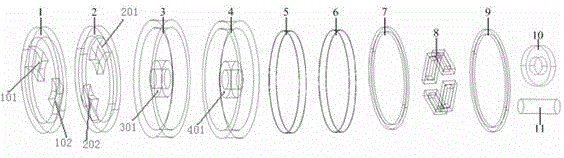
The invention discloses a radial non-coupling three-degree-of-freedom DC hybrid magnetic bearing, comprising a radial stator, an axial stator and a rotor located in the inner ring of the stator. The radial stator is composed of a left radial iron core and a right radial iron core; The right radial iron core distributes two suspension teeth evenly along the inner circumference respectively; the outer sides of the left and right stator iron cores are respectively the left and right radial magnetized permanent magnet rings; the suspension teeth are wound with centralized radial control windings; the axial stator consists of the left The axial iron core and the right axial iron core are composed; axial control windings in series are arranged on both sides of the left radial iron core and the right radial iron core and close to the inner side of the axial stator; the rotor includes a cylindrical rotor iron core and a rotating shaft. In the present invention, the static bias magnetic flux is provided by the permanent magnet ring, and the radial control magnetic flux generated by the energization of the radial control winding adjusts the corresponding bias magnetic flux. The force is uncoupled in the X‑Y direction, and the control is simple.

Figure 202010055294

Description

Radial non-coupling three-degree-of-freedom direct-current hybrid magnetic bearing
Technical Field
The invention relates to a non-mechanical contact magnetic bearing, in particular to a radial non-coupling three-degree-of-freedom direct-current hybrid magnetic bearing which can be used as a non-contact suspension support of high-speed transmission components such as a flywheel system, a machine tool electric spindle, a centrifugal machine and the like.
Background
The magnetic bearing is a novel high-performance bearing which suspends a rotor in a space by utilizing electromagnetic force between a stator and the rotor so that the stator and the rotor are not in mechanical contact. Currently, magnetic bearings are classified into the following three types according to the manner in which magnetic force is provided: (1) the active magnetic bearing generates a bias magnetic field by bias current, and the control magnetic flux generated by the control current is mutually superposed with the bias magnetic flux so as to generate controllable suspension force, and the magnetic bearing has larger volume, weight and power consumption; (2) the passive magnetic bearing has the advantages that the suspension force is completely provided by the permanent magnet, the required controller is simple, the suspension power consumption is low, but the rigidity and the damping are small, and the passive magnetic bearing is generally applied to supporting an object in one direction or reducing the load acting on the traditional bearing; (3) the hybrid magnetic bearing adopts permanent magnetic materials to replace electromagnets in an active magnetic bearing to generate a bias magnetic field, and control current only provides control magnetic flux for balancing load or interference, thereby greatly reducing the power loss of the magnetic bearing, reducing the volume of the magnetic bearing, lightening the weight of the magnetic bearing and improving the bearing capacity.
The structural commonality of the existing hybrid magnetic bearing is a single-chip structural design that all radial suspension teeth are on the same plane, and the radial suspension teeth wind a control winding to generate radial control magnetic flux which interacts with corresponding bias magnetic flux to generate radial suspension force. The radial two-degree-of-freedom suspension of the hybrid magnetic bearing with the structure is realized in a single piece, so that the suspension force is coupled in the XY direction, and the control is complex.
Disclosure of Invention
The invention aims to provide a radial non-coupling three-degree-of-freedom direct-current hybrid magnetic bearing which is simplified and controlled, has a compact structure and is convenient to manufacture and assemble.
The invention is realized by the following technical scheme:
a radial non-coupling three-degree-of-freedom direct-current hybrid magnetic bearing comprises a radial stator, an axial stator and a rotor positioned in an inner ring of the stator, wherein the radial stator comprises a left radial iron core and a right radial iron core, and the rotor comprises a rotor iron core and a rotating shaft; the left radial iron core is uniformly provided with two suspension teeth along the inner circumference and at the positions symmetrical to the directions of the + x axis and the-x axis; two suspension teeth are uniformly distributed at the positions of the right radial iron core, which are aligned with the + y axis and the-y axis along the inner circumference; the four suspension teeth are all of a zigzag structure, one end face, close to the rotor core, of each suspension tooth is matched with the circumferential face of the rotor core, the suspension teeth are the same as the rotor core in axial width and are opposite to the rotor core in position, and radial air gaps with the same air gap length are formed between the suspension teeth and the rotor core; centralized radial control windings are wound on the suspension teeth; the outer sides of the left radial iron core and the right radial iron core are respectively provided with a left radial magnetized permanent magnet ring and a right radial magnetized permanent magnet ring;
the axial stator comprises a left axial iron core and a right axial iron core, the inner diameters of the left and right axial iron cores are the same as the outer diameters of the left and right radial magnetized permanent magnetic rings, and the left and right radial magnetized permanent magnetic rings are respectively sleeved with the left and right axial iron cores; and a pair of axial control windings which are connected in series with each other are arranged on the outer sides of the left radial iron core and the right radial iron core and close to the inner ring walls of the left axial iron core and the right axial iron core, and the rotating shaft penetrates through the rotor iron core, the left axial iron core, the right axial iron core, the left radial iron core and the right radial iron core.
Furthermore, the left axial iron core and the right axial iron core are arranged oppositely, sealing surfaces are arranged on one side surface of the left axial iron core and the other side surface of the right axial iron core which is relatively far away from the left axial iron core, the sealing surfaces on the left axial iron core and the right axial iron core both use the center as a circle center to inwards extend to form a cylindrical ring, the inner diameter of the cylindrical ring is slightly larger than the outer diameter of the rotating shaft and extends to a position close to the rotor iron core, and a left axial air gap and a right axial air gap are.
Further, the left axial air gap is the same width as the right axial air gap.
Further, the left radial iron core, the right radial iron core, the left axial iron core, the right axial iron core and the rotor iron core are all made of magnetic conductive materials;
furthermore, the left and right radial magnetized permanent magnetic rings are made of rare earth permanent magnetic materials.
Has the advantages that:
1. the invention provides static bias magnetic flux under the action of the permanent magnet ring, and the radial control magnetic flux generated by electrifying the radial control winding regulates the corresponding bias magnetic flux; the hybrid magnetic bearing with the structure is independently designed in X and Y directions, adopts a double-sheet structure, and designs the suspension teeth into a zigzag structure, so that the suspension teeth in the X direction and the Y direction are coplanar with the rotor core, the suspension force is not coupled in the X-Y direction, and the control is simple.
2. The invention adds a pair of axial stators, so that the hybrid magnetic bearing of the invention generates three degrees of freedom.
Drawings
FIG. 1 is a structural diagram of a radial non-coupling three-degree-of-freedom DC hybrid magnetic bearing according to the present invention;
FIG. 2 is a schematic view of a left and right axial core of the present invention;
fig. 3 is a suspension magnetic flux diagram of the radial non-coupling three-degree-of-freedom direct-current hybrid magnetic bearing of the present invention.
1-left radial core, 101-floating tooth a, 102-floating tooth B, 2-right radial core, 201-floating tooth C, 202-floating tooth D, 3-left axial core, 301-left closed face, 302-left cylindrical ring, 4-right axial core, 401-right closed face, 402-right cylindrical ring, 5-left radial magnetized permanent magnet ring, 6-right radial magnetized permanent magnet ring, 7-left axial control winding, 8-radial control winding, 9-right axial control winding, 10-rotor core, 11-rotating shaft, 12-static bias magnetic flux, 13-right axial air gap, 14-radial air gap, 15-axial control magnetic flux, 16-left axial air gap.
Detailed Description
The present invention will be described in detail with reference to the accompanying drawings.
In the description of the present invention, it is to be understood that the terms "central," "longitudinal," "lateral," "length," "width," "thickness," "upper," "lower," "front," "rear," "left," "right," "vertical," "horizontal," "top," "bottom," "inner," "outer," "clockwise," "counterclockwise," "axial," "radial," "circumferential," and the like are used in the orientations and positional relationships indicated in the drawings for convenience in describing the invention and to simplify the description, and are not intended to indicate or imply that the referenced device or element must have a particular orientation, be constructed and operated in a particular orientation, and are not to be considered limiting of the invention.
Furthermore, the terms "first", "second" and "first" are used for descriptive purposes only and are not to be construed as indicating or implying relative importance or implicitly indicating the number of technical features indicated. Thus, a feature defined as "first" or "second" may explicitly or implicitly include at least one such feature. In the description of the present invention, "a plurality" means at least two, e.g., two, three, etc., unless specifically limited otherwise.
In the present invention, unless otherwise expressly stated or limited, the terms "mounted," "connected," "secured," and the like are to be construed broadly and can, for example, be fixedly connected, detachably connected, or integrally formed; can be mechanically or electrically connected; they may be directly connected or indirectly connected through intervening media, or they may be connected internally or in any other suitable relationship, unless expressly stated otherwise. The specific meanings of the above terms in the present invention can be understood by those skilled in the art according to specific situations.
The specific structure is shown in fig. 1, and the radial non-coupling three-degree-of-freedom direct-current hybrid magnetic bearing disclosed by the invention comprises a radial stator, an axial stator and a rotor positioned in an inner ring of the stator.
The radial stator comprises a left radial iron core 1 and a right radial iron core 2, the left radial iron core 1 and the right radial iron core 2 are of circular ring structures with the same size, two suspension teeth are uniformly distributed on the left radial iron core 1 along the inner circumference and are respectively marked as suspension teeth A101 and suspension teeth B102, and the suspension teeth A101 and the suspension teeth B102 are respectively aligned with the + x axis direction and the-x axis direction. Two suspension teeth, namely a suspension tooth C201 and a suspension tooth D202, are uniformly distributed on the right radial iron core 2 along the inner circumference, and the suspension tooth C201 and the suspension tooth D202 are respectively aligned with the + y axis direction and the-y axis direction. Referring to the attached drawing 1, namely, the suspension teeth a and B are located at two ends of the diameter of the inner ring of the left radial iron core 1, the suspension teeth C and D are located at two ends of the diameter of the inner ring of the right radial iron core 2, and the connecting line of the suspension teeth a and B is perpendicular to the connecting line of the suspension teeth C and D.
The rotor includes a cylindrical rotor core 10 and a rotating shaft 11, and the rotating shaft 11 penetrates through the rotor core 10.
And left and right radial magnetized permanent magnetic rings (5, 6) are respectively arranged on the outer sides of the left and right radial iron cores (1, 2). The four suspension teeth a101, B102, C201 and D202 are all zigzag structures, see fig. 3. The suspension teeth a101, the suspension teeth B102, the suspension teeth C201, and the suspension teeth D202 are overlapped with the orthographic projection of the left and right edges of the vertical portion of the rotor core 10, that is, one end of each of the four suspension teeth close to the rotor core 10 is the same as the axial width of the rotor core 10 and is opposite to the axial width of the rotor core 10, and the end surfaces of the four suspension teeth close to the rotor core 10 are arc-shaped end surfaces, and the radian of the end surfaces is matched with the radian of the circumferential surface of the. Radial air gaps 14 having the same air gap length are formed between the four floating teeth and the rotor core 10. And the suspension teeth A101, B102, C201 and D202 are wound with centralized radial control windings 8.
The axial stator comprises a left axial iron core 3 and a right axial iron core 4, the left axial iron core 3 and the right axial iron core 4 are of annular structures which are oppositely arranged and have the same outer diameter, a left closed surface 301 is arranged on the left side surface of the left axial iron core 3, and a right closed surface 401 is arranged on the side surface of the right axial iron core 4. Thus, the left axial iron core 3 and the right axial iron core 4 are combined to form a cylinder, the sealing surfaces on the left and right axial iron cores (3, 4) both extend inwards to form a cylinder ring by taking the center of a circle as the center, referring to fig. 2, the left sealing surface 301 of the left axial iron core 3 extends towards one side close to the right axial iron core 4 by taking the center point as the origin to form a left cylinder ring 302, and the right sealing surface 401 of the right axial iron core 4 extends towards one side close to the left axial iron core 3 by taking the center point as the origin to form a right cylinder ring 402. The inner diameters of the left cylindrical ring 302 and the right cylindrical ring 402 are slightly larger than the outer diameter of the rotating shaft 11, and the rotating shaft 11 penetrates through the left cylindrical ring 302 and the right cylindrical ring 402 after penetrating through the rotor core 10. Left cylindrical ring 302 is adjacent to the left side of rotor core 10 and forms a left axial air gap 16 with the left side of rotor core 10, and right cylindrical ring 402 is adjacent to the right side of rotor core 10 and forms a right axial air gap 13 with the right side of rotor core 10. The left axial air gap 16 is the same width as the right axial air gap 13.
The inner diameters of the circular rings of the left and right axial iron cores (3, 4) are the same as the outer diameters of the left and right radial magnetized permanent magnetic rings (5, 6), so that the left axial iron core 3 is sleeved on the left radial magnetized permanent magnetic ring 5, and the right axial iron core 4 is sleeved on the right radial magnetized permanent magnetic ring 6. Because the left and right side surfaces of the left and right axial iron cores (3, 4) are respectively provided with a closed surface, the left and right radial magnetized permanent magnet rings (5, 6), the left and right radial iron cores (1, 2), the rotor iron core 10 and the like are respectively arranged in the left and right axial iron cores (3, 4), see the attached figure 2.
A left axial control winding 7 is arranged on the left side of a left radial iron core 1 and close to a left closed surface 301 of a left axial iron core 3, a right axial control winding 9 is arranged on a right radial iron core 2 and close to a right closed surface 401 of a right axial iron core 4, the left axial control winding 7 and the right axial control winding 9 are connected in series, and the outer diameter of the left axial control winding 7 and the outer diameter of the right axial control winding 9 are equal to the inner diameter of a ring of the left axial iron core (3) and the inner diameter of a ring of the right.
The static bias magnetic flux 12 generated by the right radial magnetized permanent magnet ring 6 starts from the N pole, passes through the right axial iron core 4, the right axial air gap 13, the rotor iron core 10, the radial air gap 14, the floating teeth C201 and the floating teeth D202 on the right axial iron core 2, and returns to the S pole. The principle of the bias magnetic flux generated on the left axial iron core 1 by the permanent magnet ring 5 is the same.
The radial control magnetic flux generated in the left radial core 1 by the radial control winding 8 passes through the yoke portion of the left radial core 1, and the floating teeth a101 and B102 and the rotor core 10 form a closed circuit. The principle of the radial control magnetic flux generated in the right radial core 2 is the same.
The axial control magnetic flux 15 generated by the left and right axial control windings (7, 9) forms a closed path through the left and right axial cores (3, 4) and the left and right axial air gaps (16, 13).
Suspension principle: static bias magnetic flux 12 interacts with radial control magnetic flux and axial control magnetic flux 15 respectively, so that the superposition of air gap magnetic fields on the same side with the radial eccentric direction of the rotor is weakened, the superposition of air gap magnetic fields in the opposite direction is strengthened, force opposite to the offset direction of the rotor is generated on the rotor, and the rotor is pulled back to a radial balance position.
The technical means disclosed in the invention scheme are not limited to the technical means disclosed in the above embodiments, but also include the technical scheme formed by any combination of the above technical features. It should be noted that those skilled in the art can make various improvements and modifications without departing from the principle of the present invention, and such improvements and modifications are also considered to be within the scope of the present invention.

Claims (5)

1.一种径向无耦合三自由度直流混合磁轴承,包括径向定子、轴向定子和位于定子内圈的转子,其特征在于,1. A radial non-coupling three-degree-of-freedom DC hybrid magnetic bearing, comprising a radial stator, an axial stator and a rotor positioned in the inner ring of the stator, is characterized in that, 所述径向定子包括左径向铁心和右径向铁心,所述转子包括转子铁心与转轴;所述左径向铁心沿内圆周且与+x轴和-x轴方向对称位置均匀分布两个悬浮齿;右径向铁心沿内圆周且与+y轴和-y轴方向对称位置均匀分布两个悬浮齿;所述四个悬浮齿均为曲折型结构,其靠近转子铁心一端面与所述转子铁心圆周面匹配,且其与所述转子铁心轴向宽度相同且位置正对,悬浮齿与转子铁心间形成了气隙长度相等的径向气隙;所述悬浮齿上均绕制集中式径向控制绕组;所述左、右径向铁心的外侧分别设置左、右径向磁化永磁环;The radial stator includes a left radial iron core and a right radial iron core, and the rotor includes a rotor iron core and a rotating shaft; the left radial iron core is evenly distributed along the inner circumference and symmetrical to the +x axis and the -x axis. Suspension teeth; two suspension teeth are evenly distributed along the inner circumference of the right radial iron core and are symmetrical to the +y axis and -y axis directions; the four suspension teeth are all zigzag structures, which are close to one end face of the rotor iron core and the The circumferential surface of the rotor iron core is matched, and the axial width of the rotor iron core is the same and the position is right. A radial air gap with the same air gap length is formed between the suspension teeth and the rotor iron core; the suspension teeth are all wound with a centralized type radial control windings; left and right radially magnetized permanent magnet rings are respectively arranged on the outer sides of the left and right radial iron cores; 所述轴向定子包括左轴向铁心和右轴向铁心,所述左、右轴向铁心的内径与左、右径向磁化永磁环的外径相同且其分别套设于左、右径向磁化永磁环上;所述左、右径向铁心相对外侧且靠近左、右轴向铁心内环壁设置有一对相互串联的轴向控制绕组,所述转轴贯穿于所述转子铁心、左、右轴向铁心以及左、右径向铁心内。The axial stator includes a left axial iron core and a right axial iron core. The inner diameters of the left and right axial iron cores are the same as the outer diameters of the left and right radially magnetized permanent magnet rings, and they are respectively sleeved on the left and right diameters. On the magnetized permanent magnet ring; a pair of axial control windings connected in series are arranged on the left and right radial iron cores on the opposite outer sides and close to the inner ring walls of the left and right axial iron cores, and the rotating shaft penetrates through the rotor iron core, the left , the right axial core and the left and right radial cores. 2.根据权利要求1所述的径向无耦合三自由度直流混合磁轴承,其特征在于,所述左、右轴向铁心相对设置,其相对远离一侧面均设置封闭面,所述左、右轴向铁心上的封闭面上均以中心为圆心向内延伸形成一圆柱环,所述圆柱环内径略大于转轴外径且其延伸至靠近转子铁心处,与所述转子铁心左、右侧面之间分别形成左、右轴向气隙。2 . The radial non-coupling three-degree-of-freedom DC hybrid magnetic bearing according to claim 1 , wherein the left and right axial iron cores are arranged opposite to each other, and a closed surface is arranged on one side relatively far away from them, and the left, The closed surface on the right axial iron core extends inwardly with the center as the center of the circle to form a cylindrical ring, the inner diameter of the cylindrical ring is slightly larger than the outer diameter of the rotating shaft and it extends to the position close to the rotor iron core, which is in line with the left and right sides of the rotor iron core. Left and right axial air gaps are respectively formed between the surfaces. 3.根据权利要求2所述的一种径向无耦合三自由度直流混合磁轴承,其特征在于,所述左轴向气隙与所述右轴向气隙宽度相同。3 . The radial uncoupling three-degree-of-freedom DC hybrid magnetic bearing according to claim 2 , wherein the left axial air gap and the right axial air gap have the same width. 4 . 4.根据权利要求1至3任一所述的径向无耦合三自由度直流混合磁轴承,其特征在于,所述左、右径向铁心、左、右轴向铁心和转子铁心均由导磁材料制成。4. The radial uncoupling three-degree-of-freedom DC hybrid magnetic bearing according to any one of claims 1 to 3, wherein the left and right radial iron cores, the left and right axial iron cores and the rotor iron cores are all formed by a guide. Made of magnetic material. 5.根据权利要求1至3任一所述的径向无耦合三自由度直流混合磁轴承,其特征在于,所述左、右径向磁化永磁环为稀土永磁材料制成。5 . The radial uncoupling three-degree-of-freedom DC hybrid magnetic bearing according to claim 1 , wherein the left and right radially magnetized permanent magnet rings are made of rare earth permanent magnet materials. 6 .
CN202010055294.3A 2020-01-17 2020-01-17 Radial uncoupled three-degree-of-freedom direct current hybrid magnetic bearing Active CN111173838B (en)

Priority Applications (1)

Application Number Priority Date Filing Date Title
CN202010055294.3A CN111173838B (en) 2020-01-17 2020-01-17 Radial uncoupled three-degree-of-freedom direct current hybrid magnetic bearing

Applications Claiming Priority (1)

Application Number Priority Date Filing Date Title
CN202010055294.3A CN111173838B (en) 2020-01-17 2020-01-17 Radial uncoupled three-degree-of-freedom direct current hybrid magnetic bearing

Publications (2)

Publication Number Publication Date
CN111173838A true CN111173838A (en) 2020-05-19
CN111173838B CN111173838B (en) 2023-05-26

Family

ID=70625416

Family Applications (1)

Application Number Title Priority Date Filing Date
CN202010055294.3A Active CN111173838B (en) 2020-01-17 2020-01-17 Radial uncoupled three-degree-of-freedom direct current hybrid magnetic bearing

Country Status (1)

Country Link
CN (1) CN111173838B (en)

Cited By (2)

* Cited by examiner, † Cited by third party
Publication number Priority date Publication date Assignee Title
CN112065854A (en) * 2020-09-17 2020-12-11 淮阴工学院 A combined three-degree-of-freedom hybrid magnetic bearing with a new structure
CN116658520A (en) * 2023-05-05 2023-08-29 淮阴工学院 Outer rotor radial six-pole three-degree-of-freedom alternating current-direct current hybrid magnetic bearing and parameter design method

Citations (13)

* Cited by examiner, † Cited by third party
Publication number Priority date Publication date Assignee Title
JPH06296345A (en) * 1993-04-08 1994-10-21 Shin Meiwa Ind Co Ltd Magnetic bearing integrated in motor
DE202004020504U1 (en) * 2004-03-31 2005-08-04 Drägerwerk AG Magnetic bearing system comprises two radial bearings consisting of rotor suspended between two electromagnets, magnetic field sensors mounted on either side of stators between electromagnets being used to measure position of rotor
JP2008169965A (en) * 2007-01-15 2008-07-24 Matsushita Electric Ind Co Ltd Magnetic bearing device
CN101696713A (en) * 2009-10-15 2010-04-21 山东科技大学 Radial magnetic bearing of low-power consumption inner rotor of permanent-magnetic up-attracting and down-repelling structure
JP2011085223A (en) * 2009-10-16 2011-04-28 Hokkaido Univ Triaxial active control type magnetic bearing and rotary machine using the same
CN102322481A (en) * 2011-08-31 2012-01-18 北京航空航天大学 Radial decoupling taper magnetic bearing with three degree of freedom
CN104141685A (en) * 2014-08-06 2014-11-12 贾新涛 Driving and driven inner rotor magnetic bearing
CN107191483A (en) * 2017-04-27 2017-09-22 江苏大学 A kind of design method of the pole hybrid magnetic bearing of Three Degree Of Freedom three
CN108712047A (en) * 2018-06-30 2018-10-26 淮阴工学院 A kind of Three Degree Of Freedom bearing-free switch reluctance motor
CN108808915A (en) * 2018-06-30 2018-11-13 淮阴工学院 A kind of Three Degree Of Freedom permanent magnet type non-bearing motor
CN108847725A (en) * 2018-06-30 2018-11-20 淮阴工学院 A kind of stator permanent-magnet sheet type bearing-free switch reluctance motor
KR101963565B1 (en) * 2018-06-18 2019-03-29 주식회사 마그네타 Thrust magnetic bearing using flux switching
CN211574040U (en) * 2020-01-17 2020-09-25 淮阴工学院 Radial non-coupling three-degree-of-freedom direct-current hybrid magnetic bearing

Patent Citations (13)

* Cited by examiner, † Cited by third party
Publication number Priority date Publication date Assignee Title
JPH06296345A (en) * 1993-04-08 1994-10-21 Shin Meiwa Ind Co Ltd Magnetic bearing integrated in motor
DE202004020504U1 (en) * 2004-03-31 2005-08-04 Drägerwerk AG Magnetic bearing system comprises two radial bearings consisting of rotor suspended between two electromagnets, magnetic field sensors mounted on either side of stators between electromagnets being used to measure position of rotor
JP2008169965A (en) * 2007-01-15 2008-07-24 Matsushita Electric Ind Co Ltd Magnetic bearing device
CN101696713A (en) * 2009-10-15 2010-04-21 山东科技大学 Radial magnetic bearing of low-power consumption inner rotor of permanent-magnetic up-attracting and down-repelling structure
JP2011085223A (en) * 2009-10-16 2011-04-28 Hokkaido Univ Triaxial active control type magnetic bearing and rotary machine using the same
CN102322481A (en) * 2011-08-31 2012-01-18 北京航空航天大学 Radial decoupling taper magnetic bearing with three degree of freedom
CN104141685A (en) * 2014-08-06 2014-11-12 贾新涛 Driving and driven inner rotor magnetic bearing
CN107191483A (en) * 2017-04-27 2017-09-22 江苏大学 A kind of design method of the pole hybrid magnetic bearing of Three Degree Of Freedom three
KR101963565B1 (en) * 2018-06-18 2019-03-29 주식회사 마그네타 Thrust magnetic bearing using flux switching
CN108712047A (en) * 2018-06-30 2018-10-26 淮阴工学院 A kind of Three Degree Of Freedom bearing-free switch reluctance motor
CN108808915A (en) * 2018-06-30 2018-11-13 淮阴工学院 A kind of Three Degree Of Freedom permanent magnet type non-bearing motor
CN108847725A (en) * 2018-06-30 2018-11-20 淮阴工学院 A kind of stator permanent-magnet sheet type bearing-free switch reluctance motor
CN211574040U (en) * 2020-01-17 2020-09-25 淮阴工学院 Radial non-coupling three-degree-of-freedom direct-current hybrid magnetic bearing

Cited By (3)

* Cited by examiner, † Cited by third party
Publication number Priority date Publication date Assignee Title
CN112065854A (en) * 2020-09-17 2020-12-11 淮阴工学院 A combined three-degree-of-freedom hybrid magnetic bearing with a new structure
CN116658520A (en) * 2023-05-05 2023-08-29 淮阴工学院 Outer rotor radial six-pole three-degree-of-freedom alternating current-direct current hybrid magnetic bearing and parameter design method
CN116658520B (en) * 2023-05-05 2024-06-11 淮阴工学院 An outer rotor radial six-pole three-degree-of-freedom AC/DC hybrid magnetic bearing and parameter design method

Also Published As

Publication number Publication date
CN111173838B (en) 2023-05-26

Similar Documents

Publication Publication Date Title
CN111075839B (en) New structure radial two degrees of freedom six-pole AC/DC hybrid magnetic bearing
CN110017330B (en) Axial radial electromagnetic magnetic bearing
CN111425523A (en) A hybrid radial permanent magnet bias magnetic bearing
CN111022498B (en) Radial winding-free hybrid magnetic bearing
WO2019019243A1 (en) Alternating-current and direct-current five-degree-of-freedom hybrid magnetic bearing having dual spherical surfaces for vehicle-mounted flywheel battery
CN112953309A (en) Permanent magnet synchronous magnetic suspension motor
CN211778555U (en) Four-freedom-degree heteropolar multi-sheet structure magnetic bearing
CN111173838A (en) Radial non-coupling three-degree-of-freedom direct-current hybrid magnetic bearing
CN110131313B (en) a magnetic bearing
CN211574040U (en) Radial non-coupling three-degree-of-freedom direct-current hybrid magnetic bearing
WO2021143766A1 (en) New structure cross-tooth four-pole hybrid magnetic bearing
CN108708904A (en) Permanent-magnet bearing
CN209892623U (en) Axial radial electromagnetic magnetic bearing
CN112065856B (en) Four-pole internal and external double-rotor hybrid magnetic bearing
CN211574039U (en) New structure radial two-degree-of-freedom hexapole alternating current/direct current hybrid magnetic bearing
CN214534059U (en) Disc stator type AC/DC hybrid magnetic bearing
CN212564072U (en) A non-contact hybrid magnetic bearing with inner and outer double stators
CN215009934U (en) Five-degree-of-freedom single-winding bearingless magnetic suspension motor
CN211343731U (en) Radial mixed magnetic bearing without winding
CN211574038U (en) Radial non-coupling quadrupole hybrid magnetic bearing
CN211574037U (en) Cross-tooth quadrupole hybrid magnetic bearing with novel structure
CN102297202B (en) Single shaft controlled type five-degrees-of-freedom (DOF) miniature magnetic bearing
CN212028329U (en) New structure same-polarity quadrupole magnetic bearing
CN212272828U (en) A Radial Windingless Hybrid Magnetic Bearing Controlled by Outer Windings
CN111022499B (en) Radial large bearing capacity hybrid magnetic bearing

Legal Events

Date Code Title Description
PB01 Publication
PB01 Publication
SE01 Entry into force of request for substantive examination
GR01 Patent grant
GR01 Patent grant
EE01 Entry into force of recordation of patent licensing contract

Application publication date: 20200519

Assignee: Shanghai Yanqiao Information Technology Co.,Ltd.

Assignor: HUAIYIN INSTITUTE OF TECHNOLOGY

Contract record no.: X2023980047724

Denomination of invention: Radial uncoupled three degree of freedom DC hybrid magnetic bearing

Granted publication date: 20230526

License type: Common License

Record date: 20231121

EE01 Entry into force of recordation of patent licensing contract
TR01 Transfer of patent right

Effective date of registration: 20240322

Address after: 230000 Room 203, building 2, phase I, e-commerce Park, Jinggang Road, Shushan Economic Development Zone, Hefei City, Anhui Province

Patentee after: Hefei Jiuzhou Longteng scientific and technological achievement transformation Co.,Ltd.

Country or region after: China

Address before: 223100 A12-2, high tech Industrial Park, three East seven street, Hongze District, Huaian, Jiangsu (Hongze technology transfer center Hongze sub center)

Patentee before: HUAIYIN INSTITUTE OF TECHNOLOGY

Country or region before: China

TR01 Transfer of patent right