CN111139716A - Concrete mixing and laying integrated equipment - Google Patents
Concrete mixing and laying integrated equipment Download PDFInfo
- Publication number
- CN111139716A CN111139716A CN202010231654.0A CN202010231654A CN111139716A CN 111139716 A CN111139716 A CN 111139716A CN 202010231654 A CN202010231654 A CN 202010231654A CN 111139716 A CN111139716 A CN 111139716A
- Authority
- CN
- China
- Prior art keywords
- rotating shaft
- fixedly arranged
- cavity
- gear
- transmission
- Prior art date
- Legal status (The legal status is an assumption and is not a legal conclusion. Google has not performed a legal analysis and makes no representation as to the accuracy of the status listed.)
- Granted
Links
Images


Classifications
-
- E—FIXED CONSTRUCTIONS
- E01—CONSTRUCTION OF ROADS, RAILWAYS, OR BRIDGES
- E01C—CONSTRUCTION OF, OR SURFACES FOR, ROADS, SPORTS GROUNDS, OR THE LIKE; MACHINES OR AUXILIARY TOOLS FOR CONSTRUCTION OR REPAIR
- E01C19/00—Machines, tools or auxiliary devices for preparing or distributing paving materials, for working the placed materials, or for forming, consolidating, or finishing the paving
- E01C19/48—Machines, tools or auxiliary devices for preparing or distributing paving materials, for working the placed materials, or for forming, consolidating, or finishing the paving for laying-down the materials and consolidating them, or finishing the surface, e.g. slip forms therefor, forming kerbs or gutters in a continuous operation in situ
-
- B—PERFORMING OPERATIONS; TRANSPORTING
- B28—WORKING CEMENT, CLAY, OR STONE
- B28C—PREPARING CLAY; PRODUCING MIXTURES CONTAINING CLAY OR CEMENTITIOUS MATERIAL, e.g. PLASTER
- B28C5/00—Apparatus or methods for producing mixtures of cement with other substances, e.g. slurries, mortars, porous or fibrous compositions
- B28C5/08—Apparatus or methods for producing mixtures of cement with other substances, e.g. slurries, mortars, porous or fibrous compositions using driven mechanical means affecting the mixing
- B28C5/0806—Details; Accessories
- B28C5/0831—Drives or drive systems, e.g. toothed racks, winches
-
- B—PERFORMING OPERATIONS; TRANSPORTING
- B28—WORKING CEMENT, CLAY, OR STONE
- B28C—PREPARING CLAY; PRODUCING MIXTURES CONTAINING CLAY OR CEMENTITIOUS MATERIAL, e.g. PLASTER
- B28C5/00—Apparatus or methods for producing mixtures of cement with other substances, e.g. slurries, mortars, porous or fibrous compositions
- B28C5/08—Apparatus or methods for producing mixtures of cement with other substances, e.g. slurries, mortars, porous or fibrous compositions using driven mechanical means affecting the mixing
- B28C5/10—Mixing in containers not actuated to effect the mixing
- B28C5/12—Mixing in containers not actuated to effect the mixing with stirrers sweeping through the materials, e.g. with incorporated feeding or discharging means or with oscillating stirrers
- B28C5/16—Mixing in containers not actuated to effect the mixing with stirrers sweeping through the materials, e.g. with incorporated feeding or discharging means or with oscillating stirrers the stirrers having motion about a vertical or steeply inclined axis
-
- E—FIXED CONSTRUCTIONS
- E01—CONSTRUCTION OF ROADS, RAILWAYS, OR BRIDGES
- E01C—CONSTRUCTION OF, OR SURFACES FOR, ROADS, SPORTS GROUNDS, OR THE LIKE; MACHINES OR AUXILIARY TOOLS FOR CONSTRUCTION OR REPAIR
- E01C19/00—Machines, tools or auxiliary devices for preparing or distributing paving materials, for working the placed materials, or for forming, consolidating, or finishing the paving
- E01C19/48—Machines, tools or auxiliary devices for preparing or distributing paving materials, for working the placed materials, or for forming, consolidating, or finishing the paving for laying-down the materials and consolidating them, or finishing the surface, e.g. slip forms therefor, forming kerbs or gutters in a continuous operation in situ
- E01C19/4806—Machines, tools or auxiliary devices for preparing or distributing paving materials, for working the placed materials, or for forming, consolidating, or finishing the paving for laying-down the materials and consolidating them, or finishing the surface, e.g. slip forms therefor, forming kerbs or gutters in a continuous operation in situ with solely rollers for consolidating or finishing
Abstract
The invention discloses a concrete mixing and laying integrated device, which comprises a shell, wherein the shell comprises a mixing cavity, the mixing cavity is internally provided with a stirring mechanism, the left end wall of the mixing cavity is provided with a feeding chute, a feeding slide block is arranged in the feeding chute in a sliding way, the front side and the rear side of the feeding chute are symmetrically and rotatably provided with a first rotating shaft, the first rotating shaft is fixedly provided with a semicircular gear, the front end surface and the rear end surface of the feeding sliding block are fixedly provided with sliding racks which can be meshed with the semicircular gears, the invention has simple structure and simple and convenient operation, the equipment of the invention can directly complete the stirring and the laying of cement, and the cement is flattened, the laying mechanism of the device can evenly paint the concrete on the position needing to work, meanwhile, the proportion of cement and water can be controlled by the equipment, so that a better mixing state of the cutter is achieved, and the equipment has higher automation and integration degree.
Description
Technical Field
The invention relates to the field of concrete, in particular to concrete mixing and laying integrated equipment.
Background
As is well known, concrete is mainly used as a basic material of construction sites for building and pavement construction, the concrete needs to be mixed thoroughly before use, and the consumption of the concrete and the pavement evenness need to be considered when paving, but these are completed by separate devices on the existing construction sites, and manual assistance is needed in some cases, so that a concrete mixing and paving integrated device needs to be designed to solve the problems.
Disclosure of Invention
The invention aims to provide a concrete mixing and laying integrated device which is used for overcoming the defects in the prior art.
The invention is realized by the following technical scheme.
A concrete mixing and laying integrated device comprises a shell, a mixing cavity and a plurality of connecting rods, wherein the shell comprises the mixing cavity;
the mixing cavity is internally provided with a stirring mechanism, the left end wall of the mixing cavity is provided with a feeding chute, a feeding slide block is arranged in the feeding chute in a sliding manner, the front side and the back side of the feeding chute are symmetrically and rotatably provided with a first rotating shaft, a semicircular gear is fixedly arranged on the first rotating shaft, the front end surface and the back end surface of the feeding slide block are fixedly provided with a sliding rack which can be meshed with the semicircular gear, the upper side of the right end surface of the feeding slide block is fixedly provided with a first connecting rod, the upper side of the mixing cavity is provided with a cement cavity, the left end of the cement cavity is communicated with the left end of the mixing cavity, the right end of the first connecting rod is fixedly provided with a second connecting rod, the second connecting rod is fixedly provided with a conical base which can extend into the cement cavity, the upper end surface of the conical base is fixedly provided with a third connecting rod, an annular rack is fixedly arranged on the wall of the annular groove section, a second rotating shaft is rotationally arranged in the annular groove, a first gear is fixedly arranged on the second rotating shaft, a second gear is rotationally arranged between the first gear and the annular rack, a fourth connecting rod is fixedly arranged on the second gear, and a stirring block is fixedly arranged on the second rotating shaft in the mixing cavity and at the bottom end of the fourth connecting rod;
an external connection plate is fixedly arranged at the front end of the shell, a laying mechanism is arranged on the external connection plate, a fixed block is fixedly arranged in the external connection plate, a moving groove is arranged in the fixed block, fifth connecting rods are symmetrically and fixedly arranged at the left and right sides of the bottom end surface of the fixed block, a sixth connecting rod is fixedly arranged between the fifth connecting rods, a power block is fixedly arranged on the sixth connecting rod, a third rotating shaft is rotatably arranged in the power block, fourth rotating shafts are symmetrically and rotatably arranged at the left side and the right side of the third rotating shaft, a first transmission gear is fixedly arranged on the fourth rotating shaft, a first transmission chain is arranged between the first transmission gears, a second transmission gear which can be meshed with the first transmission chain is fixedly arranged on the third rotating shaft, the first transmission chain with it is equipped with the ring gear to rotate between the motion groove, be equipped with the bearing in the ring gear, be equipped with the eruption chamber in the bearing, eruption chamber downside is equipped with the spout.
Furthermore, a power cavity is arranged between the mixing cavity and the cement cavity, a motor is arranged on the rear end wall of the power cavity, a fifth rotating shaft is rotatably arranged on the front end surface of the motor, a first bevel gear is fixedly arranged on the second rotating shaft positioned in the power cavity, a second bevel gear which can be meshed with the first bevel gear is fixedly arranged on the fifth rotating shaft, a third transmission gear is fixedly arranged on the upper side and the lower side of the second rotating shaft positioned in the power cavity, a sixth rotating shaft is rotatably arranged at the right side of the mixing cavity, a fourth transmission gear is arranged at the upper side of the sixth rotating shaft, a second transmission chain is arranged between the fourth transmission gear and the third transmission gear, a water cavity is arranged on the right side above the power cavity, the water cavity with the hybrid chamber intercommunication is equipped with water passing pipeline, is located in the hybrid chamber the fixed fan-shaped jam piece that is equipped with of sixth pivot bottom can block up water passing pipeline.
Furthermore, a transmission cavity is arranged in the end wall of the left side of the feeding sliding block, a fifth transmission gear is fixedly arranged on the first rotating shaft in the transmission cavity, a third transmission chain is arranged between the fifth transmission gears, a seventh rotating shaft is rotatably arranged at the rear side of the transmission cavity, a third bevel gear is fixedly arranged on the first rotating shaft at the rear side, a fourth bevel gear capable of being meshed with the third bevel gear is fixedly arranged at the front end of the seventh rotating shaft, a sixth transmission gear is fixedly arranged at the rear end of the seventh rotating shaft, a seventh transmission gear is fixedly arranged at the rear end of the fifth rotating shaft, and a fourth transmission chain is arranged between the seventh transmission gear and the sixth transmission gear.
Further, a compressor is fixedly arranged on the front side of the mixing cavity, an eighth rotating shaft is arranged on the upper end face of the compressor in a rotating mode, a fifth bevel gear is fixedly arranged at the upper end of the eighth rotating shaft, a sixth bevel gear capable of being meshed with the fifth bevel gear is fixedly arranged on the front side of the fifth rotating shaft, a seventh bevel gear is fixedly arranged at the top end of the third rotating shaft, the eighth bevel gear capable of being meshed with the seventh bevel gear is fixedly arranged on the front end of the shell on the fifth rotating shaft, a first connector is arranged at the front end of the compressor, a through hole is formed between the first connector and the compressor, a second connector is arranged at the top end of the hair spraying cavity, and a hose line is arranged between the first connector and the second connector.
Further, the fixed seventh connecting rod that is equipped with of outer fishplate bar front end bilateral symmetry, the fixed external fixed block that is equipped with of outer fishplate bar downside bilateral symmetry, it is equipped with the eighth pivot to rotate on the external fixed block, the fixed stopper that is equipped with in the eighth pivot, be equipped with the spacing groove in the stopper, it is equipped with the gag lever post to slide in the spacing groove, the gag lever post with the articulated carriage release lever that is equipped with between the seventh connecting rod, the stopper front end is rotated and is equipped with the ninth pivot, the fixed rolling wheel that is equipped with in the ninth pivot.
The invention has the beneficial effects that: the cement spreading device has a simple structure, is simple and convenient to operate, can directly complete the stirring and spreading of cement, can spread the cement at a position needing to work, can control the proportion of the cement to water so as to achieve a better mixing state of the cutter, and has higher automation and integration degree.
Drawings
In order to more clearly illustrate the embodiments of the invention or the technical solutions in the prior art, the drawings used in the description of the embodiments or the prior art will be briefly described below, and it is obvious that the drawings in the following description are only some embodiments of the invention, and it is obvious for those skilled in the art that other drawings can be obtained based on these drawings without creative efforts.
FIG. 1 is a schematic structural diagram of an embodiment of the present invention;
FIG. 2 is a schematic view of the structure A-A of FIG. 1;
FIG. 3 is a schematic diagram of B-B of FIG. 1;
FIG. 4 is a schematic diagram of the structure of C-C in FIG. 1;
FIG. 5 is a schematic diagram of D-D of FIG. 1;
FIG. 6 is a schematic diagram of the structure of E-E in FIG. 5;
FIG. 7 is a schematic view of the structure of F-F in FIG. 5;
FIG. 8 is a schematic diagram of the structure of G-G in FIG. 5;
FIG. 9 is a schematic diagram of the structure of H-H in FIG. 1.
Detailed Description
The invention will now be described in detail with reference to fig. 1-9, for convenience of description, the following orientations will now be defined: the up, down, left, right, and front-back directions described below correspond to the up, down, left, right, and front-back directions in the projection relationship of fig. 1 itself.
With reference to fig. 1-9, the concrete mixing and laying integrated equipment includes a casing 10, the casing 10 includes a mixing chamber 25, a stirring mechanism 90 is contained in the mixing chamber 25, a feeding chute 15 is arranged on a left end wall of the mixing chamber 25, a feeding slider 16 is slidably arranged in the feeding chute 15, a first rotating shaft 37 is symmetrically arranged on the front side and the rear side of the feeding chute 15, a semicircular gear 38 is fixedly arranged on the first rotating shaft 37, a sliding rack 39 capable of being engaged with the semicircular gear 38 is fixedly arranged on the front end surface and the rear end surface of the feeding slider 16, a first connecting rod 18 is fixedly arranged on the upper side of the right end surface of the feeding slider 16, a cement chamber 11 is arranged on the upper side of the mixing chamber 25, the left end of the cement chamber 11 is communicated with the left end of the mixing chamber 25, a second connecting rod 19 is fixedly arranged on the right end of the first connecting rod 18, a conical base 14 capable of extending into the cement chamber 11 is fixedly arranged, a third connecting rod 13 is fixedly arranged on the upper end face of the conical base 14, an annular disc 12 is fixedly arranged on the upper end face of the third connecting rod 13, an annular groove 84 is formed in the top end wall of the mixing cavity 25, an annular rack 20 is fixedly arranged on the section wall of the annular groove 84, a second rotating shaft 34 is rotatably arranged in the annular groove 84, a first gear 24 is fixedly arranged on the second rotating shaft 34, a second gear 23 is rotatably arranged between the first gear 24 and the annular rack 20, a fourth connecting rod 22 is fixedly arranged on the second gear 23, and a stirring block 21 is fixedly arranged on the second rotating shaft 34 in the mixing cavity 25 and at the bottom end of the fourth connecting rod 22;
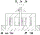
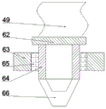
an outer connecting plate 50 is fixedly arranged at the front end of the shell 10, a laying mechanism 91 is arranged on the outer connecting plate 50, a fixed block 51 is fixedly arranged in the outer connecting plate 50, a moving groove 56 is arranged in the fixed block 51, fifth connecting rods 61 are fixedly arranged on the bottom end surfaces of the fixed blocks 51 in a bilateral symmetry manner, sixth connecting rods 60 are fixedly arranged between the fifth connecting rods 61, a power block 59 is fixedly arranged on the sixth connecting rods 60, a third rotating shaft 54 is rotatably arranged in the power block 59, fourth rotating shafts 53 are symmetrically and rotatably arranged on the left side and the right side of the third rotating shaft 54, a first transmission gear 52 is fixedly arranged on the fourth rotating shafts 53, a first transmission chain 55 is arranged between the first transmission gears 52, a second transmission gear 85 capable of being meshed with the first transmission chain 55 is fixedly arranged on the third rotating shaft 54, a gear ring 63 is rotatably arranged between the first transmission chain 55 and the moving groove 56, a bearing 65 is arranged in the gear ring 63, a hair spray cavity 64 is arranged in the bearing 65, and a nozzle 66 is arranged on the lower side of the hair spray cavity 64.
The mixing cavity 25 and the cement cavity 11 are provided with a power cavity 32 therebetween, the rear end wall of the power cavity 32 is provided with a motor 76, the front end face of the motor 76 rotates to be provided with a fifth rotating shaft 80, the second rotating shaft 34 in the power cavity 32 is fixedly provided with a first bevel gear 36, the fifth rotating shaft 80 is fixedly provided with a second bevel gear 33 which can be meshed with the first bevel gear 36, the upper side and the lower side of the second rotating shaft 34 in the power cavity 32 are fixedly provided with a third transmission gear 35, the right side of the mixing cavity 25 is rotatably provided with a sixth rotating shaft 28, the upper side of the sixth rotating shaft 28 is provided with a fourth transmission gear 30, a second transmission chain 31 is arranged between the fourth transmission gear 30 and the third transmission gear 35, the right side above the power cavity 32 is provided with a water cavity 29, the water cavity 29 is communicated with the mixing cavity 25 and provided with a water passing pipeline 27, and the bottom of the sixth rotating shaft 28 in the mixing cavity 25 is fixedly provided with a fan which can block the water Forming a plugging block 26.
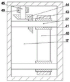
A transmission cavity 17 is arranged in the left end wall of the feeding slider 16, a fifth transmission gear 41 is fixedly arranged on the first rotating shaft 37 in the transmission cavity 17, a third transmission chain 40 is arranged between the fifth transmission gears 41, a seventh rotating shaft 45 is rotatably arranged at the rear side of the transmission cavity 17, a third bevel gear 43 is fixedly arranged on the first rotating shaft 37 at the rear side, a fourth bevel gear 44 capable of being meshed with the third bevel gear 43 is fixedly arranged at the front end of the seventh rotating shaft 45, a sixth transmission gear 46 is fixedly arranged at the rear end of the seventh rotating shaft 45, a seventh transmission gear 78 is fixedly arranged at the rear end of the fifth rotating shaft 80, and a fourth transmission chain 77 is arranged between the seventh transmission gear 78 and the sixth transmission gear 46.
The mixing chamber 25 is fixedly provided with a compressor 42 at the front side, an eighth rotating shaft 82 is rotatably arranged on the upper end surface of the compressor 42, a fifth bevel gear 83 is fixedly arranged at the upper end of the eighth rotating shaft 82, a sixth bevel gear 79 capable of being meshed with the fifth bevel gear 83 is fixedly arranged on the front side of the fifth rotating shaft 80, a seventh bevel gear 57 is fixedly arranged at the top end of the third rotating shaft 54, an eighth bevel gear 81 capable of being meshed with the seventh bevel gear 57 is fixedly arranged at the front end of the shell 10 on the fifth rotating shaft 80, a first connector 48 is arranged at the front end of the compressor 42, a through hole 47 is formed between the first connector 48 and the compressor 42, a second connector 62 is arranged at the top end of the hair spray chamber 64, and a hose passage 49 is arranged between the first connector 48 and the second connector 62.
Fixed seventh connecting rod 72 that is equipped with of 50 front end bilateral symmetry of outer fishplate bar, 50 downside bilateral symmetry of outer fishplate bar are fixed and are equipped with external fixed block 68, it is equipped with eighth pivot 67 to rotate on the external fixed block 68, the fixed stopper 69 that is equipped with in the eighth pivot 67, be equipped with spacing groove 70 in the stopper 69, it is equipped with gag lever post 73 to slide in the spacing groove 70, gag lever post 73 with it is equipped with carriage release lever 71 to articulate between the seventh connecting rod 72, stopper 69 front end is rotated and is equipped with ninth pivot 75, the fixed rolling wheel 74 that is equipped with in the ninth pivot 75.
The working state is as follows:
the equipment is arranged on a moving trolley, the motor 76 is started to drive the fifth rotating shaft 80 to rotate, the fifth rotating shaft 80 rotates to drive the seventh transmission gear 78 to rotate, the seventh transmission gear 78 rotates to drive the sixth transmission gear 46 to rotate through the fourth transmission chain 77, the sixth transmission gear 46 rotates to drive the fourth bevel gear 44 to rotate through the seventh rotating shaft 45, the fourth bevel gear 44 rotates to drive the third bevel gear 43 to rotate, the third bevel gear 43 rotates to drive the fifth transmission gear 41 to rotate, the fifth transmission gear 41 rotates to drive the first rotating shaft 37 which is symmetrical front and back through the third transmission chain 40 to rotate, the first rotating shaft 37 rotates to drive the semi-circular gear 38 to rotate, the semi-circular gear 38 rotates to enable the feeding slide block 16 to slide up and down through being meshed with the sliding rack 39, the feeding slide block 16 slides up and down to drive the second connecting rod 19 to slide up and down through the first connecting rod 18, the second connecting rod 19 slides up and down to transport cement contained in the cement cavity 11 to the mixing cavity 25 through the conical base 14 and the annular disc 12, the fifth rotating shaft 80 rotates to drive the first bevel gear 36 to rotate through the second bevel gear 33, the first bevel gear 36 rotates to drive the second rotating shaft 34 to rotate, the second rotating shaft 34 rotates to drive the sixth rotating shaft 28 to rotate through the second transmission chain 31, the sixth rotating shaft 28 rotates to drive the fan-shaped plugging block 26 to rotate, the fan-shaped plugging block 26 rotates to intermittently put water in the water cavity 29 into the mixing cavity 25 through the water passing pipe 27, the second rotating shaft 34 rotates to drive the first gear 24 to rotate, and the first gear 24 rotates to drive the second gear 23 to rotate, the second gear 23 and the second rotating shaft 34 rotate to mix cement and water sufficiently through the stirring block 21, the fifth rotating shaft 80 rotates to drive the sixth bevel gear 79 to rotate, the sixth bevel gear 79 rotates to drive the eighth rotating shaft 82 to rotate through the first bevel gear 36, the eighth rotating shaft 82 rotates to drive the compressor 42 to be started, the compressor 42 is started to press mixed concrete into the hose line 49 to be transported into the spraying cavity 64, the fifth rotating shaft 80 drives the eighth bevel gear 81 to rotate, the eighth bevel gear 81 rotates to drive the third rotating shaft 54 to rotate through the seventh bevel gear 57, the third rotating shaft 54 rotates to drive the first transmission chain 55 to rotate, the first transmission chain 55 rotates to drive the gear ring 63 to rotate and slide in the moving groove 56, and meanwhile, the concrete in the spraying cavity 64 is discharged through the spraying opening 66, the equipment removes and passes through rolling wheel 74 flattens the concrete, when needs adjust the height of rolling wheel 74, manual promotion carriage release lever 71, carriage release lever 71 passes through gag lever post 73 with spacing groove 70 cooperation makes stopper 69 moves down, will rolling wheel 74 moves down.
The above embodiments are merely illustrative of the technical ideas and features of the present invention, and the purpose thereof is to enable those skilled in the art to understand the contents of the present invention and implement the present invention, and not to limit the protection scope of the present invention. All equivalent changes and modifications made according to the spirit of the present invention should be covered within the protection scope of the present invention.
Claims (5)
1. The utility model provides an integrative equipment is laid in concrete mixture, includes the casing, its characterized in that: the housing includes a mixing chamber;
the mixing cavity is internally provided with a stirring mechanism, the left end wall of the mixing cavity is provided with a feeding chute, a feeding slide block is arranged in the feeding chute in a sliding manner, the front side and the back side of the feeding chute are symmetrically and rotatably provided with a first rotating shaft, a semicircular gear is fixedly arranged on the first rotating shaft, the front end surface and the back end surface of the feeding slide block are fixedly provided with a sliding rack which can be meshed with the semicircular gear, the upper side of the right end surface of the feeding slide block is fixedly provided with a first connecting rod, the upper side of the mixing cavity is provided with a cement cavity, the left end of the cement cavity is communicated with the left end of the mixing cavity, the right end of the first connecting rod is fixedly provided with a second connecting rod, the second connecting rod is fixedly provided with a conical base which can extend into the cement cavity, the upper end surface of the conical base is fixedly provided with a third connecting rod, an annular rack is fixedly arranged on the wall of the annular groove section, a second rotating shaft is rotationally arranged in the annular groove, a first gear is fixedly arranged on the second rotating shaft, a second gear is rotationally arranged between the first gear and the annular rack, a fourth connecting rod is fixedly arranged on the second gear, and a stirring block is fixedly arranged on the second rotating shaft in the mixing cavity and at the bottom end of the fourth connecting rod;
an external connection plate is fixedly arranged at the front end of the shell, a laying mechanism is arranged on the external connection plate, a fixed block is fixedly arranged in the external connection plate, a moving groove is arranged in the fixed block, fifth connecting rods are symmetrically and fixedly arranged at the left and right sides of the bottom end surface of the fixed block, a sixth connecting rod is fixedly arranged between the fifth connecting rods, a power block is fixedly arranged on the sixth connecting rod, a third rotating shaft is rotatably arranged in the power block, fourth rotating shafts are symmetrically and rotatably arranged at the left side and the right side of the third rotating shaft, a first transmission gear is fixedly arranged on the fourth rotating shaft, a first transmission chain is arranged between the first transmission gears, a second transmission gear which can be meshed with the first transmission chain is fixedly arranged on the third rotating shaft, the first transmission chain with it is equipped with the ring gear to rotate between the motion groove, be equipped with the bearing in the ring gear, be equipped with the eruption chamber in the bearing, eruption chamber downside is equipped with the spout.
2. The concrete mixing and laying integrated equipment according to claim 1, wherein: a power cavity is arranged between the mixing cavity and the cement cavity, a motor is arranged on the rear end wall of the power cavity, a fifth rotating shaft is rotatably arranged on the front end surface of the motor, a first bevel gear is fixedly arranged on the second rotating shaft positioned in the power cavity, a second bevel gear which can be meshed with the first bevel gear is fixedly arranged on the fifth rotating shaft, a third transmission gear is fixedly arranged on the upper side and the lower side of the second rotating shaft positioned in the power cavity, a sixth rotating shaft is rotatably arranged at the right side of the mixing cavity, a fourth transmission gear is arranged at the upper side of the sixth rotating shaft, a second transmission chain is arranged between the fourth transmission gear and the third transmission gear, a water cavity is arranged on the right side above the power cavity, the water cavity with the hybrid chamber intercommunication is equipped with water passing pipeline, is located in the hybrid chamber the fixed fan-shaped jam piece that is equipped with of sixth pivot bottom can block up water passing pipeline.
3. The concrete mixing and laying integrated equipment according to claim 1, wherein: a transmission cavity is arranged in the end wall of the left side of the feeding sliding block, a fifth transmission gear is fixedly arranged on the first rotating shaft in the transmission cavity, a third transmission chain is arranged between the fifth transmission gears, a seventh rotating shaft is rotatably arranged at the rear side of the transmission cavity, a third bevel gear is fixedly arranged on the first rotating shaft at the rear side, a fourth bevel gear capable of being meshed with the third bevel gear is fixedly arranged at the front end of the seventh rotating shaft, a sixth transmission gear is fixedly arranged at the rear end of the seventh rotating shaft, a seventh transmission gear is fixedly arranged at the rear end of the fifth rotating shaft, and a fourth transmission chain is arranged between the seventh transmission gear and the sixth transmission gear.
4. The concrete mixing and laying integrated equipment according to claim 1, wherein: the mixing chamber is characterized in that a compressor is fixedly arranged on the front side of the mixing chamber, an eighth rotating shaft is arranged on the upper end face of the compressor in a rotating mode, a fifth bevel gear is fixedly arranged at the upper end of the eighth rotating shaft, a sixth bevel gear capable of being meshed with the fifth bevel gear is fixedly arranged on the front side of the fifth rotating shaft, a seventh bevel gear is fixedly arranged at the top end of the third rotating shaft, the fifth rotating shaft is located at the front end of the shell and is fixedly provided with an eighth bevel gear capable of being meshed with the seventh bevel gear, a first connector is arranged at the front end of the compressor, a through hole is formed between the first connector and the compressor, a second connector is arranged at the top end of the hair spraying chamber, and a hose line is arranged.
5. The concrete mixing and laying integrated equipment according to claim 1, wherein: the fixed seventh connecting rod that is equipped with of outer fishplate bar front end bilateral symmetry, the fixed external fixed block that is equipped with of outer fishplate bar downside bilateral symmetry, it is equipped with the eighth pivot to rotate on the external fixed block, the fixed stopper that is equipped with in the eighth pivot, be equipped with the spacing groove in the stopper, it is equipped with the gag lever post to slide in the spacing groove, the gag lever post with the articulated carriage release lever that is equipped with between the seventh connecting rod, the stopper front end is rotated and is equipped with the ninth pivot, the fixed rolling wheel that is equipped with in the ninth pivot.
Priority Applications (2)
| Application Number | Priority Date | Filing Date | Title |
|---|---|---|---|
| CN202010231654.0A CN111139716B (en) | 2020-03-28 | 2020-03-28 | Concrete mixing and laying integrated equipment |
| GBGB2008061.0A GB202008061D0 (en) | 2020-03-28 | 2020-05-29 | An integrated device for mixing and laying concrete |
Applications Claiming Priority (1)
| Application Number | Priority Date | Filing Date | Title |
|---|---|---|---|
| CN202010231654.0A CN111139716B (en) | 2020-03-28 | 2020-03-28 | Concrete mixing and laying integrated equipment |
Publications (2)
| Publication Number | Publication Date |
|---|---|
| CN111139716A true CN111139716A (en) | 2020-05-12 |
| CN111139716B CN111139716B (en) | 2021-01-26 |
Family
ID=70528789
Family Applications (1)
| Application Number | Title | Priority Date | Filing Date |
|---|---|---|---|
| CN202010231654.0A Active CN111139716B (en) | 2020-03-28 | 2020-03-28 | Concrete mixing and laying integrated equipment |
Country Status (2)
| Country | Link |
|---|---|
| CN (1) | CN111139716B (en) |
| GB (1) | GB202008061D0 (en) |
Cited By (2)
| Publication number | Priority date | Publication date | Assignee | Title |
|---|---|---|---|---|
| US20200360880A1 (en) * | 2019-04-29 | 2020-11-19 | Paul Sleightholme | Method and Apparatus for Applying Cementitious Polyurethane |
| CN113578672A (en) * | 2021-08-11 | 2021-11-02 | 海南赛诺实业有限公司 | Coating device |
Citations (6)
| Publication number | Priority date | Publication date | Assignee | Title |
|---|---|---|---|---|
| CN206591790U (en) * | 2017-03-30 | 2017-10-27 | 吴志军 | A kind of concrete paving and leveling all-in-one |
| CN108824145A (en) * | 2018-07-06 | 2018-11-16 | 咸宁职业技术学院 | A kind of concrete speading for construction is mechanical |
| CN208277146U (en) * | 2018-03-16 | 2018-12-25 | 中冶东北建设(沈阳)工程技术有限公司 | A kind of dedicated concrete slab of Construction of Civil Engineering pours device |
| CN208410235U (en) * | 2018-03-01 | 2019-01-22 | 王轩堃 | A kind of subway shield tunnel construction cement sand mixed stirring device |
| CN110258233A (en) * | 2019-06-27 | 2019-09-20 | 倡创(上海)咨询管理事务所 | The construction method of concrete road surface |
| CN209887865U (en) * | 2018-10-10 | 2020-01-03 | 福建省福乾建设发展有限公司 | High-efficient cement mixing apparatus for construction |
-
2020
- 2020-03-28 CN CN202010231654.0A patent/CN111139716B/en active Active
- 2020-05-29 GB GBGB2008061.0A patent/GB202008061D0/en not_active Ceased
Patent Citations (6)
| Publication number | Priority date | Publication date | Assignee | Title |
|---|---|---|---|---|
| CN206591790U (en) * | 2017-03-30 | 2017-10-27 | 吴志军 | A kind of concrete paving and leveling all-in-one |
| CN208410235U (en) * | 2018-03-01 | 2019-01-22 | 王轩堃 | A kind of subway shield tunnel construction cement sand mixed stirring device |
| CN208277146U (en) * | 2018-03-16 | 2018-12-25 | 中冶东北建设(沈阳)工程技术有限公司 | A kind of dedicated concrete slab of Construction of Civil Engineering pours device |
| CN108824145A (en) * | 2018-07-06 | 2018-11-16 | 咸宁职业技术学院 | A kind of concrete speading for construction is mechanical |
| CN209887865U (en) * | 2018-10-10 | 2020-01-03 | 福建省福乾建设发展有限公司 | High-efficient cement mixing apparatus for construction |
| CN110258233A (en) * | 2019-06-27 | 2019-09-20 | 倡创(上海)咨询管理事务所 | The construction method of concrete road surface |
Cited By (4)
| Publication number | Priority date | Publication date | Assignee | Title |
|---|---|---|---|---|
| US20200360880A1 (en) * | 2019-04-29 | 2020-11-19 | Paul Sleightholme | Method and Apparatus for Applying Cementitious Polyurethane |
| GB2595636A (en) * | 2019-04-29 | 2021-12-08 | Sleightholme Paul | Method and apparatus for applying cementitious polyurethane |
| GB2595636B (en) * | 2019-04-29 | 2022-08-03 | Sleightholme Paul | Method and apparatus for applying cementitious polyurethane |
| CN113578672A (en) * | 2021-08-11 | 2021-11-02 | 海南赛诺实业有限公司 | Coating device |
Also Published As
| Publication number | Publication date |
|---|---|
| CN111139716B (en) | 2021-01-26 |
| GB202008061D0 (en) | 2020-07-15 |
Similar Documents
| Publication | Publication Date | Title |
|---|---|---|
| CN111139716B (en) | Concrete mixing and laying integrated equipment | |
| CN107433686A (en) | A kind of build concrete high-efficiency stirring equipment | |
| CN107160564A (en) | A kind of liftable building concrete mixer of puddler | |
| CN207224285U (en) | A kind of build concrete high-efficiency stirring equipment | |
| CN106363804A (en) | Efficient raw material mixing device for cement brick manufacturing | |
| CN206326741U (en) | A kind of novel cement mixer | |
| CN211201073U (en) | Wall spraying device for building construction | |
| CN110975682A (en) | Powder mixing arrangement is used in gardens maintenance | |
| CN201288423Y (en) | Multifunctional ash mortar agitating and spraying machine | |
| CN203487753U (en) | Automatic blending and pasting machine | |
| CN107127889B (en) | A kind of concrete central mix plant | |
| CN112195732A (en) | Automatic brick paving machine for building construction | |
| CN106926362B (en) | A kind of mud rapid recharge device | |
| CN220219064U (en) | Building sand ash mixer | |
| CN205386869U (en) | Movable concrete mixer | |
| CN206899490U (en) | A kind of environment-friendly type ready-mixed concrete preparation facilities mixed with building waste | |
| CN107433682B (en) | A kind of bridge construction material blending device | |
| CN218083438U (en) | Concrete mixing device for construction | |
| CN217204093U (en) | Grouting device for hydraulic engineering construction | |
| CN217752039U (en) | Mortar stirring dust keeper that breathes freely | |
| CN218375313U (en) | Concrete placement equipment for building | |
| CN220150798U (en) | Floor tile paving device for paving cement mortar | |
| CN211806947U (en) | Sand air entrainment building block raw materials batching compounding device | |
| CN220909710U (en) | Tunnel preliminary bracing shotcrete work platform | |
| CN209699508U (en) | A kind of portable external concrete mixing arrangement |
Legal Events
| Date | Code | Title | Description |
|---|---|---|---|
| PB01 | Publication | ||
| PB01 | Publication | ||
| SE01 | Entry into force of request for substantive examination | ||
| SE01 | Entry into force of request for substantive examination | ||
| TA01 | Transfer of patent application right |
Effective date of registration: 20210106 Address after: 233700 Guohu formation, Southwest Village, Wangzhuang Town, Guzhen County, Bengbu City, Anhui Province Applicant after: Guzhen Quansheng new building materials Co.,Ltd. Address before: No.143, nanguangminggang Road, Taijiang District, Fuzhou City, Fujian Province 350000 Applicant before: Fuzhou Taijiang zhutu Technology Co.,Ltd. |
|
| TA01 | Transfer of patent application right | ||
| GR01 | Patent grant | ||
| GR01 | Patent grant |