CN111133821A - Rate matching for New Radio (NR) Physical Downlink Shared Channel (PDSCH) and Physical Uplink Shared Channel (PUSCH) - Google Patents
Rate matching for New Radio (NR) Physical Downlink Shared Channel (PDSCH) and Physical Uplink Shared Channel (PUSCH) Download PDFInfo
- Publication number
- CN111133821A CN111133821A CN201880061742.1A CN201880061742A CN111133821A CN 111133821 A CN111133821 A CN 111133821A CN 201880061742 A CN201880061742 A CN 201880061742A CN 111133821 A CN111133821 A CN 111133821A
- Authority
- CN
- China
- Prior art keywords
- res
- rmr
- configuration
- cell
- transmission
- Prior art date
- Legal status (The legal status is an assumption and is not a legal conclusion. Google has not performed a legal analysis and makes no representation as to the accuracy of the status listed.)
- Pending
Links
Images


Classifications
-
- H—ELECTRICITY
- H04—ELECTRIC COMMUNICATION TECHNIQUE
- H04L—TRANSMISSION OF DIGITAL INFORMATION, e.g. TELEGRAPHIC COMMUNICATION
- H04L5/00—Arrangements affording multiple use of the transmission path
- H04L5/0001—Arrangements for dividing the transmission path
- H04L5/0003—Two-dimensional division
- H04L5/0005—Time-frequency
- H04L5/0007—Time-frequency the frequencies being orthogonal, e.g. OFDM(A), DMT
-
- H—ELECTRICITY
- H04—ELECTRIC COMMUNICATION TECHNIQUE
- H04L—TRANSMISSION OF DIGITAL INFORMATION, e.g. TELEGRAPHIC COMMUNICATION
- H04L1/00—Arrangements for detecting or preventing errors in the information received
- H04L1/0001—Systems modifying transmission characteristics according to link quality, e.g. power backoff
- H04L1/0009—Systems modifying transmission characteristics according to link quality, e.g. power backoff by adapting the channel coding
- H04L1/0013—Rate matching, e.g. puncturing or repetition of code symbols
-
- H—ELECTRICITY
- H04—ELECTRIC COMMUNICATION TECHNIQUE
- H04L—TRANSMISSION OF DIGITAL INFORMATION, e.g. TELEGRAPHIC COMMUNICATION
- H04L5/00—Arrangements affording multiple use of the transmission path
- H04L5/0001—Arrangements for dividing the transmission path
- H04L5/0003—Two-dimensional division
- H04L5/0005—Time-frequency
- H04L5/0007—Time-frequency the frequencies being orthogonal, e.g. OFDM(A), DMT
- H04L5/001—Time-frequency the frequencies being orthogonal, e.g. OFDM(A), DMT the frequencies being arranged in component carriers
-
- H—ELECTRICITY
- H04—ELECTRIC COMMUNICATION TECHNIQUE
- H04L—TRANSMISSION OF DIGITAL INFORMATION, e.g. TELEGRAPHIC COMMUNICATION
- H04L5/00—Arrangements affording multiple use of the transmission path
- H04L5/0001—Arrangements for dividing the transmission path
- H04L5/0028—Variable division
-
- H—ELECTRICITY
- H04—ELECTRIC COMMUNICATION TECHNIQUE
- H04L—TRANSMISSION OF DIGITAL INFORMATION, e.g. TELEGRAPHIC COMMUNICATION
- H04L5/00—Arrangements affording multiple use of the transmission path
- H04L5/003—Arrangements for allocating sub-channels of the transmission path
- H04L5/0048—Allocation of pilot signals, i.e. of signals known to the receiver
- H04L5/005—Allocation of pilot signals, i.e. of signals known to the receiver of common pilots, i.e. pilots destined for multiple users or terminals
-
- H—ELECTRICITY
- H04—ELECTRIC COMMUNICATION TECHNIQUE
- H04L—TRANSMISSION OF DIGITAL INFORMATION, e.g. TELEGRAPHIC COMMUNICATION
- H04L5/00—Arrangements affording multiple use of the transmission path
- H04L5/0091—Signaling for the administration of the divided path
-
- H—ELECTRICITY
- H04—ELECTRIC COMMUNICATION TECHNIQUE
- H04W—WIRELESS COMMUNICATION NETWORKS
- H04W72/00—Local resource management
- H04W72/12—Wireless traffic scheduling
- H04W72/1263—Mapping of traffic onto schedule, e.g. scheduled allocation or multiplexing of flows
- H04W72/1268—Mapping of traffic onto schedule, e.g. scheduled allocation or multiplexing of flows of uplink data flows
-
- H—ELECTRICITY
- H04—ELECTRIC COMMUNICATION TECHNIQUE
- H04W—WIRELESS COMMUNICATION NETWORKS
- H04W72/00—Local resource management
- H04W72/12—Wireless traffic scheduling
- H04W72/1263—Mapping of traffic onto schedule, e.g. scheduled allocation or multiplexing of flows
- H04W72/1273—Mapping of traffic onto schedule, e.g. scheduled allocation or multiplexing of flows of downlink data flows
-
- H—ELECTRICITY
- H04—ELECTRIC COMMUNICATION TECHNIQUE
- H04W—WIRELESS COMMUNICATION NETWORKS
- H04W72/00—Local resource management
- H04W72/20—Control channels or signalling for resource management
- H04W72/21—Control channels or signalling for resource management in the uplink direction of a wireless link, i.e. towards the network
-
- H—ELECTRICITY
- H04—ELECTRIC COMMUNICATION TECHNIQUE
- H04B—TRANSMISSION
- H04B7/00—Radio transmission systems, i.e. using radiation field
- H04B7/02—Diversity systems; Multi-antenna system, i.e. transmission or reception using multiple antennas
- H04B7/04—Diversity systems; Multi-antenna system, i.e. transmission or reception using multiple antennas using two or more spaced independent antennas
- H04B7/0413—MIMO systems
-
- H—ELECTRICITY
- H04—ELECTRIC COMMUNICATION TECHNIQUE
- H04L—TRANSMISSION OF DIGITAL INFORMATION, e.g. TELEGRAPHIC COMMUNICATION
- H04L5/00—Arrangements affording multiple use of the transmission path
- H04L5/003—Arrangements for allocating sub-channels of the transmission path
- H04L5/0032—Distributed allocation, i.e. involving a plurality of allocating devices, each making partial allocation
- H04L5/0035—Resource allocation in a cooperative multipoint environment
-
- H—ELECTRICITY
- H04—ELECTRIC COMMUNICATION TECHNIQUE
- H04L—TRANSMISSION OF DIGITAL INFORMATION, e.g. TELEGRAPHIC COMMUNICATION
- H04L5/00—Arrangements affording multiple use of the transmission path
- H04L5/003—Arrangements for allocating sub-channels of the transmission path
- H04L5/0044—Arrangements for allocating sub-channels of the transmission path allocation of payload
-
- H—ELECTRICITY
- H04—ELECTRIC COMMUNICATION TECHNIQUE
- H04L—TRANSMISSION OF DIGITAL INFORMATION, e.g. TELEGRAPHIC COMMUNICATION
- H04L5/00—Arrangements affording multiple use of the transmission path
- H04L5/003—Arrangements for allocating sub-channels of the transmission path
- H04L5/0048—Allocation of pilot signals, i.e. of signals known to the receiver
-
- H—ELECTRICITY
- H04—ELECTRIC COMMUNICATION TECHNIQUE
- H04L—TRANSMISSION OF DIGITAL INFORMATION, e.g. TELEGRAPHIC COMMUNICATION
- H04L5/00—Arrangements affording multiple use of the transmission path
- H04L5/003—Arrangements for allocating sub-channels of the transmission path
- H04L5/0053—Allocation of signaling, i.e. of overhead other than pilot signals
-
- H—ELECTRICITY
- H04—ELECTRIC COMMUNICATION TECHNIQUE
- H04L—TRANSMISSION OF DIGITAL INFORMATION, e.g. TELEGRAPHIC COMMUNICATION
- H04L5/00—Arrangements affording multiple use of the transmission path
- H04L5/003—Arrangements for allocating sub-channels of the transmission path
- H04L5/0058—Allocation criteria
- H04L5/0073—Allocation arrangements that take into account other cell interferences
Abstract
Certain aspects of the present disclosure relate to methods and apparatus related to rate matching for a New Radio (NR) Physical Downlink Shared Channel (PDSCH) and a Physical Uplink Shared Channel (PUSCH). In certain aspects, a method comprises: a Rate Matching Resource (RMR) configuration is received from a serving cell. The method further comprises the following steps: identifying one or more first Resource Elements (REs) to rate match around based at least in part on a transmission number scheme associated with the RMR configuration, wherein the one or more first REs are used for Reference Signal (RS) transmission in a serving cell or a neighboring cell. The method further comprises the following steps: mapping a Physical Downlink Shared Channel (PDSCH) to one or more second REs that do not include the first REs.
Description
Cross Reference to Related Applications
The present application claims the benefit of application No. pct/CN2017/104081 entitled "RATE MATCHING FOR New Road (NR) PHYSICAL DOWNLINK SHARED CHANNEL (PDSCH) AND PHYSICAL UPLINK Shared Channel (PUSCH)" filed on 28/9/2017. The entire contents of the above application are incorporated herein by reference.
Technical Field
The present disclosure relates generally to communication systems, and more particularly, to methods and apparatus related to rate matching for a New Radio (NR) Physical Downlink Shared Channel (PDSCH) and a Physical Uplink Shared Channel (PUSCH).
Background
Wireless communication systems are widely deployed to provide various telecommunication services such as telephony, video, data, messaging, and broadcasting. Typical wireless communication systems may employ multiple-access techniques capable of supporting communication with multiple users by sharing the available system resources (e.g., bandwidth, transmit power). Examples of such multiple-access techniques include Long Term Evolution (LTE) systems, Code Division Multiple Access (CDMA) systems, Time Division Multiple Access (TDMA) systems, Frequency Division Multiple Access (FDMA) systems, Orthogonal Frequency Division Multiple Access (OFDMA) systems, single carrier frequency division multiple access (SC-FDMA) systems, and time division synchronous code division multiple access (TD-SCDMA) systems.
In some examples, a wireless multiple-access communication system may include multiple base stations, each supporting communication for multiple communication devices (otherwise referred to as User Equipment (UE)) simultaneously. In an LTE or LTE-a network, a set of one or more base stations may define an evolved node b (enb). In other examples (e.g., in a next generation or 5G network), a wireless multiple-access communication system may include a plurality of Distributed Units (DUs) (e.g., Edge Units (EUs), Edge Nodes (ENs), Radio Heads (RHs), intelligent radio heads (SRHs), Transmit Receive Points (TRPs), etc.) in communication with a plurality of Central Units (CUs) (e.g., Central Nodes (CNs), Access Node Controllers (ANCs), etc.), wherein a set of one or more distributed units in communication with a central unit may define an access node (e.g., a new radio base station (NR BS), a new radio node b (NR NB), a network node, a 5G NB, an eNB, etc.). A base station or DU may communicate with a set of UEs on downlink channels (e.g., for transmissions from the base station to the UEs) and uplink channels (e.g., for transmissions from the UEs to the base station or distributed units).
These multiple access techniques have been employed in various telecommunications standards to provide a common protocol that enables different wireless devices to communicate on a city, country, region, and even global level. An example of an emerging telecommunications standard is New Radio (NR), e.g., 5G radio access. NR is an enhanced set of LTE mobile standards promulgated by the third generation partnership project (3 GPP). It is designed to better integrate with other open standards by improving spectral efficiency, reducing costs, improving services, utilizing new spectrum, and using OFDMA with Cyclic Prefix (CP) on Downlink (DL) and on Uplink (UL), thereby better supporting mobile broadband internet access, as well as supporting beamforming, Multiple Input Multiple Output (MIMO) antenna technology, and carrier aggregation.
However, as the demand for mobile broadband access continues to grow, there is a desire for further improvement in NR technology. Preferably, these improvements should be applicable to other multiple access techniques and telecommunications standards employing these techniques.
Disclosure of Invention
The systems, methods, and devices of the present disclosure each have several aspects, no single one of which is solely responsible for its desirable attributes. Without limiting the scope of the present disclosure as expressed by the claims that follow, some features will now be discussed briefly. After considering this discussion, and particularly after reading the section entitled "detailed description" one will understand how the features of this disclosure provide advantages that include improved communication between access points and stations in a wireless network.
Certain aspects provide a method for wireless communications by a User Equipment (UE). In summary, the method comprises: receiving a Rate Matching Resource (RMR) configuration from a serving cell; identifying one or more first Resource Elements (REs) to rate match around based at least in part on a transmission numerology (RMR) associated with the RMR configuration, wherein the one or more first REs are used for Reference Signal (RS) transmission in the serving cell or a neighboring cell; and mapping a Physical Downlink Shared Channel (PDSCH) to one or more second REs that do not include the first REs.
Certain aspects provide a method for wireless communications by a User Equipment (UE). In summary, the method comprises: receiving a Rate Matching Resource (RMR) configuration from a serving cell; identifying one or more first Resource Elements (REs) to be rate matched around for a Physical Uplink Shared Channel (PUSCH) based at least in part on a signaling configuration in the RMR configuration related to a Physical Uplink Control Channel (PUCCH) and a Sounding Reference Signal (SRS); and mapping a Physical Uplink Shared Channel (PUSCH) to one or more second REs that do not include the first RE.
In general, aspects include methods, apparatuses, systems, computer-readable media, and processing systems substantially as described herein with reference to and as illustrated by the accompanying drawings.
To the accomplishment of the foregoing and related ends, the one or more aspects comprise the features hereinafter fully described and particularly pointed out in the claims. The following description and the annexed drawings set forth in detail certain illustrative features of the one or more aspects. These features are indicative, however, of but a few of the various ways in which the principles of various aspects may be employed and the description is intended to include all such aspects and their equivalents.
Drawings
So that the manner in which the above recited features of the present disclosure can be understood in detail, a more particular description, briefly summarized above, may be had by reference to aspects, some of which are illustrated in the appended drawings. It is to be noted, however, that the appended drawings illustrate only certain typical aspects of this disclosure and are therefore not to be considered limiting of its scope, for the description may admit to other equally effective aspects.
Fig. 1 is a block diagram conceptually illustrating an example telecommunications system in accordance with certain aspects of the present disclosure.
Fig. 2 is a block diagram illustrating an example logical architecture of a distributed RAN in accordance with certain aspects of the present disclosure.
Fig. 3 is a diagram illustrating an example physical architecture of a distributed RAN in accordance with certain aspects of the present disclosure.
Fig. 4 is a block diagram conceptually illustrating a design of an example BS and User Equipment (UE), in accordance with certain aspects of the present disclosure.
Fig. 5 is a diagram illustrating an example for implementing a communication protocol stack in accordance with certain aspects of the present disclosure.
Fig. 6 illustrates an example of a DL-centric subframe in accordance with certain aspects of the present disclosure.
Fig. 7 illustrates an example of a UL-centric subframe in accordance with certain aspects of the present disclosure.
Fig. 8 illustrates an example of a UE located in an overlapping coverage area of two cells in accordance with certain aspects of the present disclosure.
Fig. 9 illustrates example operations for wireless communications by a wireless device in accordance with aspects of the present disclosure.
Fig. 9A illustrates a wireless communication device that may include various components configured to perform operations for the techniques disclosed herein, such as one or more of the operations illustrated in fig. 9.
Fig. 10 shows an example of a primary cell using a larger subcarrier spacing (SCS) compared to neighboring cells, in accordance with aspects of the present disclosure.
Fig. 11 shows an example of a primary cell using a smaller subcarrier spacing (SCS) compared to neighboring cells, in accordance with aspects of the present disclosure.
Fig. 12 illustrates example operations for wireless communications by a wireless device, in accordance with aspects of the present disclosure.
Fig. 12A illustrates a wireless communication device that may include various components configured to perform operations for the techniques disclosed herein, such as one or more of the operations illustrated in fig. 12.
Fig. 13A illustrates a set of resources reserved for a semi-static configuration of a long Physical Uplink Control Channel (PUCCH) in an Uplink (UL) normal burst, in accordance with aspects of the present disclosure.
Fig. 13B illustrates rate matching to avoid all Resource Elements (REs) in the long PUCCH region, according to aspects of the present disclosure.
Fig. 14A also shows a set of resources reserved for semi-static configuration of long PUCCH in UL regular bursts, in accordance with aspects of the present disclosure.
Fig. 14B shows REs to be occupied by PUSCH that are not occupied by PUCCH in a region allocated for PUCCH according to aspects of the present disclosure.
Fig. 15 shows example symbols in the UL short duration of a slot in accordance with aspects of the present disclosure.
Fig. 16 shows an example set of precoders according to aspects of the present disclosure.
Fig. 17 illustrates an example rate matching resource in accordance with aspects of the present disclosure.
To facilitate understanding, identical reference numerals have been used, where possible, to designate identical elements that are common to the figures. It is contemplated that elements disclosed in one aspect may be beneficially utilized on other aspects without specific recitation.
Detailed Description
Aspects of the present disclosure relate to methods and apparatus related to rate matching for a New Radio (NR) Physical Downlink Shared Channel (PDSCH) and a Physical Uplink Shared Channel (PUSCH).
Aspects of the present disclosure provide apparatuses, methods, processing systems, and computer-readable media for a New Radio (NR) (new radio access technology or 5G technology).
NR may support various wireless communication services, such as enhanced mobile broadband (eMBB) targeting wide bandwidths (e.g., over 80MHz), millimeter wave (mmW) targeting high carrier frequencies (e.g., 60GHz), massive MTC (MTC) targeting non-backward compatible MTC technologies, and/or mission critical targeting ultra-reliable low latency communication (URLLC). These services may include latency and reliability requirements. These services may also have different Transmission Time Intervals (TTIs) to meet corresponding quality of service (QoS) requirements. In addition, these services may coexist in the same subframe.
Typically, wireless devices that conform to a wireless standard, such as the Long Term Evolution (LTE) standard or the 5G New Radio (NR) standard, use uplink and downlink reference signals for channel estimation or equalization. In some cases, any interference with the downlink or uplink reference signals may result in inaccurate estimates of the reference signals by the receiver. To prevent this, for example, a User Equipment (UE) that is receiving downlink reference signals may need to avoid interference from: aperiodic channel state information reference signals (a-CSI-RS) of other UEs, CSI-RS of other cells, Synchronization Signals (SS) of other cells, aperiodic Sounding Reference Signal (SRS) structure for a-SRS if SRS can be multiplexed with Physical Uplink Shared Channel (PUSCH), Physical Uplink Control Channel (PUCCH) structure if unused PUCCH resources can be used for PUSCH, signals/channels in legacy systems (e.g., LTE cell specific reference signals (CSR)/SS, Phase Tracking Reference Signals (PTRS), tracking reference signals, etc.).
Certain embodiments discussed herein relate to configuring a UE to perform Physical Downlink Shared Channel (PDSCH) rate matching around non-zero power CSI-RSs (nzp CSI-RSs) in neighboring cells in order to enable the UE to accurately estimate Reference Signal Received Power (RSRP) on CSI-RSs detected from cells other than the cell transmitting the PDSCH. Further, certain embodiments discussed herein relate to configuring a UE to perform PUSCH rate matching around a Physical Uplink Control Channel (PUCCH) on the Uplink (UL).
The following description provides examples without limiting the scope, applicability, or examples set forth in the claims. Changes may be made in the function and arrangement of elements discussed without departing from the scope of the disclosure. Various examples may omit, substitute, or add various procedures or components as appropriate. For example, the described methods may be performed in an order different than that described, and various steps may be added, omitted, or combined. Furthermore, features described with respect to some examples may be combined into some other examples. For example, an apparatus may be implemented or a method may be practiced using any number of the aspects set forth herein. Moreover, the scope of the present disclosure is intended to cover such an apparatus or method implemented with other structure, functionality, or structure and functionality in addition to or other than the various aspects of the disclosure set forth herein. It should be understood that any aspect of the disclosure disclosed herein may be embodied by one or more elements of a claim. The word "exemplary" is used herein to mean "serving as an example, instance, or illustration. Any aspect described herein as "exemplary" is not necessarily to be construed as preferred or advantageous over other aspects.
The techniques described herein may be used for various wireless communication networks, such as LTE, CDMA, TDMA, FDMA, OFDMA, SC-FDMA, and others. The terms "network" and "system" are often used interchangeably. A CDMA network may implement a radio technology such as Universal Terrestrial Radio Access (UTRA), CDMA2000, etc. UTRA includes wideband CDMA (wcdma) and other variants of CDMA. cdma2000 covers IS-2000, IS-95 and IS-856 standards. TDMA networks may implement radio technologies such as global system for mobile communications (GSM). An OFDMA network may implement radio technologies such as NR (e.g., 5G RA), evolved UTRA (E-UTRA), Ultra Mobile Broadband (UMB), IEEE 802.11(Wi-Fi), IEEE 802.16(WiMAX), IEEE802.20, flash-OFDMA, and the like. UTRA and E-UTRA are part of the Universal Mobile Telecommunications System (UMTS). NR is an emerging wireless communication technology under development that incorporates the 5G technology forum (5 GTF). 3GPP Long Term Evolution (LTE) and LTE-advanced (LTE-A) are releases of UMTS that use E-UTRA. UTRA, E-UTRA, UMTS, LTE-A, and GSM are described in documents from an organization entitled "third Generation partnership project" (3 GPP). Cdma2000 and UMB are described in documents from an organization named "third generation partnership project 2" (3GPP 2). The techniques described herein may be used for the wireless networks and radio technologies mentioned above as well as other wireless networks and radio technologies. For clarity, although aspects may be described herein using terms commonly associated with 3G and/or 4G wireless technologies, aspects of the present disclosure may be applied to other generation-based communication systems (e.g., 5G and beyond technologies, including NR technologies).
Example Wireless communication System
Fig. 1 shows an example wireless network 100, such as a New Radio (NR) or 5G network, in which aspects of the present disclosure may be performed. For example, UE120 may perform operation 900 of fig. 9 and operation 1200 of fig. 12.
As shown in fig. 1, wireless network 100 may include multiple BSs 110 and other network entities. The BS may be a station communicating with the UE. Each BS 110 may provide communication coverage for a particular geographic area. In 3GPP, the term "cell" can refer to a coverage area of a node B and/or a node B subsystem serving that coverage area, depending on the context in which the term is used. In an NR system, the term "cell" and eNB, node B, 5G NB, AP, NR BS or TRP may be interchanged. In some examples, a cell may not necessarily be stationary, and the geographic area of the cell may move according to the location of the mobile base station. In some examples, the base stations may be interconnected with each other and/or with one or more other base stations or network nodes (not shown) in wireless network 100 by various types of backhaul interfaces (e.g., interfaces that are directly physically connected, virtual networks, or use any suitable transport networks).
In general, any number of wireless networks may be deployed in a given geographic area. Each wireless network may support a particular Radio Access Technology (RAT) and may operate on one or more frequencies. A RAT may also be referred to as a radio technology, air interface, etc. The frequencies may also be referred to as carriers, frequency channels, etc. Each frequency may support a single RAT in a given geographic area in order to avoid interference between wireless networks having different RATs. In some cases, NR or 5G RAT networks may be deployed.
The BS may provide communication coverage for a macrocell, picocell, femtocell, and/or other type of cell. A macro cell may cover a relatively large geographic area (e.g., several kilometers in radius) and may allow unrestricted access by UEs with service subscriptions. A pico cell may cover a relatively small geographic area and may allow unrestricted access by UEs with service subscriptions. A femto cell may cover a relatively small geographic area (e.g., a residence) and may allow restricted access by UEs having an association with the femto cell (e.g., UEs in a Closed Subscriber Group (CSG), UEs for users in the residence, etc.). The BS for the macro cell may be referred to as a macro BS. The BS for the pico cell may be referred to as a pico BS. The BS for the femto cell may be referred to as a femto BS or a home BS. In the example shown in fig. 1, BSs 110a, 110b, and 110c may be macro BSs for macro cells 102a, 102b, and 102c, respectively. BS 110x may be a pico BS for pico cell 102 x. BSs 110y and 110z may be femto BSs for femtocells 102y and 102z, respectively. A BS may support one or more (e.g., three) cells.
The wireless network 100 may be a heterogeneous network including different types of BSs (e.g., macro BSs, pico BSs, femto BSs, repeaters, etc.). These different types of BSs may have different transmit power levels, different coverage areas, and different effects on interference in wireless network 100. For example, macro BSs may have a high transmit power level (e.g., 20 watts), while pico BSs, femto BSs, and repeaters may have a lower transmit power level (e.g., 1 watt).
UEs 120 (e.g., 120x, 120y, etc.) may be dispersed throughout wireless network 100, and each UE may be stationary or mobile. A UE may also be referred to as a mobile station, a terminal, an access terminal, a subscriber unit, a station, a Customer Premises Equipment (CPE), a cellular telephone, a smartphone, a Personal Digital Assistant (PDA), a wireless modem, a wireless communication device, a handheld device, a laptop, a cordless telephone, a Wireless Local Loop (WLL) station, a tablet device, a camera, a gaming device, a netbook, a smartbook, an ultrabook, a medical device or medical apparatus, a biometric sensor/device, a wearable device (e.g., a smartwatch, a smart garment, smart glasses, a smart wristband, smart jewelry (e.g., a smart ring, a smart bracelet, etc.)), an entertainment device (e.g., a music device, a video device, a satellite radio, etc.), a vehicle component or sensor, a smart meter/sensor, an industrial manufacturing device, a global positioning system device, a satellite radio, etc, Or any other suitable device configured to communicate via a wireless or wired medium. Some UEs may be considered evolved or Machine Type Communication (MTC) devices or evolved MTC (emtc) devices. MTC and eMTC UEs include, for example, a robot, a drone, a remote device, a sensor, a meter, a monitor, a location tag, etc., which may communicate with a BS, another device (e.g., a remote device), or some other entity. The wireless nodes may provide connectivity, for example, to or from a network (e.g., a wide area network such as the internet or a cellular network) via wired or wireless communication links. Some UEs may be considered internet of things (IoT) devices. In fig. 1, a solid line with double arrows indicates desired transmissions between a UE and a serving BS, which is a BS designated to serve the UE on the downlink and/or uplink. The dashed line with double arrows indicates interfering transmissions between the UE and the BS.
Some wireless networks (e.g., LTE) utilize Orthogonal Frequency Division Multiplexing (OFDM) on the downlink and single carrier frequency division multiplexing (SC-FDM) on the uplink. OFDM and SC-FDM partition the system bandwidth into multiple (K) orthogonal subcarriers, which are also commonly referred to as tones, bins, and so on. Each subcarrier may be modulated with data. Typically, modulation symbols are sent in the frequency domain with OFDM and in the time domain with SC-FDM. The spacing between adjacent subcarriers may be fixed, and the total number of subcarriers (K) may depend on the system bandwidth. For example, the spacing of the subcarriers may be 15kHz and the minimum resource allocation (referred to as a "resource block") may be 12 subcarriers (or 180 kHz). Thus, for a system bandwidth of 1.25, 2.5, 5, 10, or 20 megahertz (MHz), the nominal FFT size may be equal to 128, 256, 512, 1024, or 2048, respectively. The system bandwidth may also be divided into subbands. For example, a sub-band may cover 1.08MHz (i.e., 6 resource blocks), and there may be 1, 2, 4, 8, or 16 sub-bands for a system bandwidth of 1.25, 2.5, 5, 10, or 20MHz, respectively.
Although aspects of the examples described herein may be associated with LTE technology, aspects of the disclosure may be applied with other wireless communication systems (e.g., NRs). NR may utilize OFDM with CP on the uplink and downlink, and may include support for half-duplex operation using Time Division Duplex (TDD). A single component carrier bandwidth of 100MHz may be supported. The NR resource block may span 12 subcarriers having a subcarrier bandwidth of 75kHz in 0.1ms duration. Each radio frame may consist of 50 subframes, having a length of 10 ms. Thus, each subframe may have a length of 0.2 ms. Each subframe may indicate a link direction (i.e., DL or UL) for data transmission, and the link direction for each subframe may be dynamically switched. Each subframe may include DL/UL data as well as DL/UL control data. The UL and DL subframes for NR may be as described in more detail below. Beamforming may be supported and beam directions may be dynamically configured. MIMO transmission with precoding may also be supported. A MIMO configuration in the DL may support up to 8 transmit antennas, with a multi-layer DL transmitting up to 8 streams and up to 2 streams per UE. Multi-layer transmission with up to 2 streams per UE may be supported. Aggregation of multiple cells with up to 8 serving cells may be supported. Alternatively, the NR may support a different air interface than the OFDM-based air interface. The NR network may comprise entities such as CUs and/or DUs.
In some examples, access to the air interface may be scheduled, where a scheduling entity (e.g., a base station) allocates resources for communication among some or all of the devices and apparatuses within its service area or cell. Within this disclosure, the scheduling entity may be responsible for scheduling, allocating, reconfiguring, and releasing resources for one or more subordinate entities, as discussed further below. That is, for scheduled communications, the subordinate entity utilizes the resources allocated by the scheduling entity. The base station is not the only entity that can be used as a scheduling entity. That is, in some examples, a UE may serve as a scheduling entity that schedules resources for one or more subordinate entities (e.g., one or more other UEs). In this example, the UE is acting as a scheduling entity, while other UEs utilize the resources scheduled by the UE for wireless communication. The UE may serve as a scheduling entity in a peer-to-peer (P2P) network and/or in a mesh network. In the mesh network example, in addition to communicating with the scheduling entity, the UEs may optionally communicate directly with each other.
Thus, in a wireless communication network having scheduled access to time-frequency resources and having a cellular configuration, a P2P configuration, and a mesh configuration, a scheduling entity and one or more subordinate entities may communicate utilizing the scheduled resources.
As mentioned above, the RAN may include CUs and DUs. An NR BS (e.g., eNB, 5G node B, transmission reception point (TPR), Access Point (AP)) may correspond to one or more BSs. The NR cell may be configured as an access cell (ACell) or a data cell only (DCell). For example, a RAN (e.g., a central unit or a distributed unit) may configure a cell. The DCell may be a cell for carrier aggregation or dual connectivity, but not for initial access, cell selection/reselection, or handover. In some cases, the DCell may not transmit synchronization signals — in some cases, the DCell may transmit SSs. The NR BS may transmit a downlink signal indicating a cell type to the UE. Based on the cell type indication, the UE may communicate with the NR BS. For example, the UE may determine the NR BSs to consider for cell selection, access, handover, and/or measurement based on the indicated cell type.
Fig. 2 illustrates an example logical architecture of a distributed Radio Access Network (RAN)200 that may be implemented in the wireless communication system shown in fig. 1. The 5G access node 206 may include an Access Node Controller (ANC) 202. ANC may be a Central Unit (CU) of the distributed RAN 200. The backhaul interface to the next generation core network (NG-CN)204 may terminate at the ANC. The backhaul interface to the neighboring next generation access node (NG-AN) may terminate at the ANC. An ANC may include one or more TRPs 208 (which may also be referred to as a BS, NR BS, node B, 5G NB, AP, or some other terminology). As described above, TRP may be used interchangeably with "cell".
TRP208 may be a DU. A TRP may be attached to one ANC (ANC 202) or more than one ANC (not shown). For example, for RAN sharing, radio as a service (RaaS), AND service-specific AND deployments, a TRP may be connected to more than one ANC. The TRP may include one or more antenna ports. The TRP may be configured to provide services to the UE either individually (e.g., dynamic selection) or jointly (e.g., joint transmission).
The local architecture 200 may be used to illustrate the fronthaul definition. The architecture may be defined to support a fronthaul scheme across different deployment types. For example, the architecture may be based on the transmitting network capabilities (e.g., bandwidth, latency, and/or jitter).
The architecture may share features and/or components with LTE. According to aspects, the next generation AN (NG-AN)210 may support dual connectivity with NRs. The NG-ANs may share a common fronthaul for LTE and NR.
This architecture may enable collaboration between TRPs 208, both pairwise and between multiple ones. For example, cooperation may be pre-configured within and/or across the TRP via the ANC 202. According to aspects, no inter-TRP interface may be required/present.
According to aspects, there may be a dynamic configuration of split logic functionality in the architecture 200. As will be described in more detail with reference to fig. 5, a Radio Resource Control (RRC) layer, a Packet Data Convergence Protocol (PDCP) layer, a Radio Link Control (RLC) layer, a Medium Access Control (MAC) layer, and a Physical (PHY) layer may be adaptively placed at a DU or a CU (e.g., TRP or ANC, respectively). According to certain aspects, a BS may include a Central Unit (CU) (e.g., ANC 202) and/or one or more distributed units (e.g., one or more TRPs 208).
Fig. 3 illustrates an example physical architecture of a distributed RAN 300, in accordance with aspects of the present disclosure. A centralized core network unit (C-CU)302 may host core network functions. The C-CU may be deployed centrally. The C-CU functions may be offloaded (e.g., to Advanced Wireless Services (AWS)) to handle peak capacity.
A centralized RAN unit (C-RU)304 may host one or more ANC functions. Alternatively, the C-RU may locally host the core network functions. The C-RU may have a distributed deployment. The C-RU may be closer to the network edge.
Fig. 4 illustrates example components of BS 110 and UE120 shown in fig. 1 that may be used to implement aspects of the present disclosure. As described above, the BS may include TRP. One or more components in BS 110 and UE120 may be used to implement aspects of the present disclosure. For example, antennas 452, Tx/Rx 222, processors 466, 458, 464, and/or controller/processor 480 of UE120, and/or antennas 434, processors 460, 420, 438, and/or controller/processor 440 of BS 110 may be used to perform the operations described herein (e.g., operation 9000 of fig. 9 and operation 1200 of fig. 12).
Fig. 4 shows a block diagram of a design of BS 110 and UE120 (which may be one of the BSs and one of the UEs in fig. 1). For the restricted association scenario, base station 110 may be macro BS 110c in fig. 1, and UE120 may be UE120 y. The base station 110 may also be some other type of base station. Base station 110 may be equipped with antennas 434a through 434t, and UE120 may be equipped with antennas 452a through 452 r.
At base station 110, a transmit processor 420 may receive data from a data source 412 and control information from a controller/processor 440. The control information may be for a Physical Broadcast Channel (PBCH), a Physical Control Format Indicator Channel (PCFICH), a physical hybrid ARQ indicator channel (PHICH), a Physical Downlink Control Channel (PDCCH), etc. The data may be for a Physical Downlink Shared Channel (PDSCH), etc. Processor 420 may process (e.g., encode and symbol map) the data and control information to obtain data symbols and control symbols, respectively. Processor 420 may also generate reference symbols, e.g., for PSS, SSS, and cell-specific reference signals. A Transmit (TX) multiple-input multiple-output (MIMO) processor 430 may perform spatial processing (e.g., precoding) on the data symbols, the control symbols, and/or the reference symbols, if applicable, and may provide output symbol streams to Modulators (MODs) 432a through 432 t. For example, TX MIMO processor 430 may perform certain aspects described herein for RS multiplexing. Each modulator 432 may process a respective output symbol stream (e.g., for OFDM, etc.) to obtain an output sample stream. Each modulator 432 may further process (e.g., convert to analog, amplify, filter, and upconvert) the output sample stream to obtain a downlink signal. Downlink signals from modulators 432a through 432t may be transmitted via antennas 434a through 434t, respectively.
At UE120, antennas 452a through 452r may receive downlink signals from base station 110 and may provide received signals to demodulators (DEMODs) 454a through 454r, respectively. Each demodulator 454 may condition (e.g., filter, amplify, downconvert, and digitize) a respective received signal to obtain input samples. Each demodulator 454 may further process the input samples (e.g., for OFDM, etc.) to obtain received symbols. A MIMO detector 456 may obtain received symbols from all demodulators 454a through 454r, perform MIMO detection on the received symbols (if applicable), and provide detected symbols. For example, MIMO detector 456 provides detected RSs that are transmitted using the techniques described herein. A receive processor 458 may process (e.g., demodulate, deinterleave, and decode) the detected symbols, provide decoded data for the UE120 to a data sink 460, and provide decoded control information to a controller/processor 480. According to one or more scenarios, the CoMP aspects may include providing antennas and some Tx/Rx functionality such that they are located in a distributed unit. For example, some Tx/Rx processing may be done in a central unit, while other processing may be done at distributed units. For example, BS modulator/demodulator 432 may be in a distributed unit in accordance with one or more aspects as illustrated in the figures.
On the uplink, at UE120, a transmit processor 464 may receive and process data from a data source 462 (e.g., for a Physical Uplink Shared Channel (PUSCH)) and control information from a controller/processor 480 (e.g., for a Physical Uplink Control Channel (PUCCH)). The transmit processor 464 may also generate reference symbols for a reference signal. The symbols from transmit processor 464 may be precoded by a TX MIMO processor 466 if applicable, further processed by demodulators 454a through 454r (e.g., for SC-FDM, etc.), and transmitted to base station 110. At BS 110, the uplink signals from UE120 may be received by antennas 434, processed by modulators 432, detected by a MIMO detector 436 (if applicable), and further processed by a receive processor 438 to obtain decoded data and control information sent by UE 120. A receive processor 438 may provide decoded data to a data sink 439 and decoded control information to a controller/processor 440.
Controllers/ processors 440 and 480 may direct the operation at base station 110 and UE120, respectively. Processor 440 and/or other processors and modules at base station 110 may perform or direct the execution of functional blocks such as those shown in fig. 9 and/or other processes for the techniques described herein. Processor 480 and/or other processors and modules at UE120 may also perform or direct processes for the techniques described herein. Memories 442 and 482 may store data and program codes for BS 110 and UE120, respectively. A scheduler 444 may schedule UEs for data transmission on the downlink and/or uplink.
Fig. 5 shows a diagram 500 depicting an example for implementing a communication protocol stack, in accordance with aspects of the present disclosure. The illustrated communication protocol stack may be implemented by a device operating in a 5G system (e.g., a system supporting uplink-based mobility). Diagram 500 shows a communication protocol stack that includes a Radio Resource Control (RRC) layer 510, a Packet Data Convergence Protocol (PDCP) layer 515, a Radio Link Control (RLC) layer 520, a Medium Access Control (MAC) layer 525, and a Physical (PHY) layer 530. In various examples, the layers of the protocol stack may be implemented as separate software modules, portions of a processor or ASIC, portions of non-co-located devices connected by a communications link, or various combinations thereof. The collocated and non-collocated implementations may be used, for example, in a protocol stack for a network access device (e.g., AN, CU, and/or DU) or UE.
A first option 505-a illustrates a split implementation of a protocol stack, where the implementation of the protocol stack is split between a centralized network access device (e.g., ANC 202 in fig. 2) and a distributed network access device (e.g., DU 208 in fig. 2). In the first option 505-a, the RRC layer 510 and the PDCP layer 515 may be implemented by a central unit, while the RLC layer 520, the MAC layer 525 and the PHY layer 530 may be implemented by DUs. In various examples, a CU and a DU may be co-located or non-co-located. The first option 505-a may be useful in a macrocell, microcell, or picocell deployment.
A second option 505-b illustrates a unified implementation of a protocol stack, wherein the protocol stack is implemented in a single network access device (e.g., Access Node (AN), new radio base station (NR BS), new radio node b (NR nb), Network Node (NN), etc.). In a second option, the RRC layer 510, PDCP layer 515, RLC layer 520, MAC layer 525, and PHY layer 530 may all be implemented by the AN. The second option 505-b may be useful in femtocell deployments.
Regardless of whether the network access device implements part or all of the protocol stack, the UE may implement the entire protocol stack (e.g., RRC layer 510, PDCP layer 515, RLC layer 520, MAC layer 525, and PHY layer 530).
Fig. 6 is a diagram 600 illustrating an example of a DL-centric subframe. The DL-centric subframe may include a control portion 602. The control portion 602 may exist at an initial or beginning portion of a subframe centered on the DL. The control portion 602 may include various scheduling information and/or control information corresponding to various portions of a DL-centric subframe. In some configurations, the control portion 602 may be a Physical DL Control Channel (PDCCH), as indicated in fig. 6. The DL centric sub-frame may also include a DL data portion 604. The DL data portion 604 may sometimes be referred to as the payload of a DL-centric subframe. The DL data portion 604 may include communication resources for transmitting DL data from a scheduling entity (e.g., a UE or BS) to a subordinate entity (e.g., a UE). In some configurations, the DL data portion 604 may be a Physical DL Shared Channel (PDSCH).
The DL-centric sub-frame may also include a common UL portion 606. Common UL portion 606 may sometimes be referred to as an UL burst, a common UL burst, and/or various other suitable terms. The common UL portion 606 may include feedback information corresponding to various other portions of the DL-centric sub-frame. For example, the common UL portion 606 may include feedback information corresponding to the control portion 602. Non-limiting examples of feedback information may include ACK signals, NACK signals, HARQ indicators, and/or various other suitable types of information. The common UL portion 606 may include additional or alternative information, such as information related to Random Access Channel (RACH) procedures, Scheduling Requests (SRs), and various other suitable types of information. As shown in fig. 6, the end of the DL data portion 604 may be separated in time from the beginning of the common UL portion 606. Such temporal separation may sometimes be referred to as a gap, guard period, guard interval, and/or various other suitable terms. This separation provides time for switching from DL communications (e.g., receive operations by a subordinate entity (e.g., a UE)) to UL communications (e.g., transmissions by a subordinate entity (e.g., a UE)). Those skilled in the art will appreciate that the foregoing is merely one example of a DL-centric subframe and that alternative structures with similar features may exist without necessarily departing from aspects described herein.
Fig. 7 is a diagram 700 illustrating an example of a UL-centric subframe. The UL-centric sub-frame may include a control portion 702. The control portion 702 may exist at an initial or beginning portion of a UL-centric sub-frame. The control portion 702 in fig. 7 may be similar to the control portion described above with reference to fig. 6. The UL-centric sub-frame may also include a UL data portion 704. The UL data portion 704 may sometimes be referred to as the payload of a UL-centric subframe. The UL data portion may refer to a communication resource for transmitting UL data from a subordinate entity (e.g., a UE) to a scheduling entity (e.g., a UE or a BS). In some configurations, control portion 702 may be a Physical DL Control Channel (PDCCH).
As shown in fig. 7, the end of the control portion 702 may be separated in time from the beginning of the UL data portion 704. Such temporal separation may sometimes be referred to as a gap, guard period, guard interval, and/or various other suitable terms. This separation provides time for switching from DL communications (e.g., receive operations by the scheduling entity) to UL communications (e.g., transmissions by the scheduling entity). The UL-centric sub-frame may also include a common UL portion 706. The common UL portion 706 in fig. 7 may be similar to the common UL portion 706 described above with reference to fig. 7. Common UL portion 706 may additionally or alternatively include Channel Quality Indicator (CQI), Sounding Reference Signal (SRS), and various other suitable types of information. Those skilled in the art will appreciate that the foregoing is merely one example of a UL-centric subframe and that alternative structures having similar features may exist without necessarily departing from aspects described herein.
In some cases, two or more subordinate entities (e.g., UEs) may communicate with each other using sidelink signals. Real-world applications of such sidelink communications may include public safety, proximity services, UE-to-network relays, vehicle-to-vehicle (V2V) communications, internet of everything (IoE) communications, IoT communications, mission critical meshes, and/or various other suitable applications. In general, sidelink signals may refer to signals transmitted from one subordinate entity (e.g., UE1) to another subordinate entity (e.g., UE2) without the need to relay the communication through a scheduling entity (e.g., UE or BS), even though the scheduling entity may be used for scheduling and/or control purposes. In some examples, the sidelink signals may be transmitted using licensed spectrum (as opposed to wireless local area networks that typically use unlicensed spectrum).
The UE may operate in various radio resource configurations including configurations associated with transmitting pilots using a set of dedicated resources (e.g., Radio Resource Control (RRC) dedicated state, etc.), or configurations associated with transmitting pilots using a set of common resources (e.g., RRC common state, etc.). When operating in the RRC dedicated state, the UE may select a set of dedicated resources to transmit pilot signals to the network. When operating in the RRC common state, the UE may select a set of common resources to transmit pilot signals to the network. In either case, the pilot signal transmitted by the UE may be received by one or more network access devices (e.g., AN or DU or portions thereof). Each receiving network access device may be configured to receive and measure pilot signals transmitted on a common set of resources and also receive and measure pilot signals transmitted on a set of dedicated resources allocated to UEs for which the network access device is a member of the set of network access devices monitoring for the UE. CUs receiving one or more of the network access devices, or receiving measurements to which the network access devices send pilot signals, may use the measurements to identify serving cells for the UEs, or initiate changes to serving cells for one or more of the UEs.
Rate matching for New Radio (NR) Physical Downlink Shared Channel (PDSCH) and Physical Uplink Shared Channel (PUSCH)
Typically, wireless devices that conform to a wireless standard, such as the Long Term Evolution (LTE) standard or the 5G New Radio (NR) standard, use uplink and downlink reference signals for channel estimation or equalization. In some cases, any interference with the downlink or uplink reference signals may result in inaccurate estimates of the reference signals by the receiver. To prevent this, for example, a User Equipment (UE) that is receiving downlink reference signals may need to avoid interference from: aperiodic channel state information reference signals (a-CSI-RS) of other UEs, CSI-RS of other cells, Synchronization Signals (SS) of other cells, aperiodic Sounding Reference Signal (SRS) structure for a-SRS if SRS can be multiplexed with Physical Uplink Shared Channel (PUSCH), Physical Uplink Control Channel (PUCCH) structure if unused PUCCH resources can be used for PUSCH, signals/channels in legacy systems (e.g., LTE cell specific reference signals (CSR)/SS, Phase Tracking Reference Signals (PTRS), tracking reference signals, etc.).
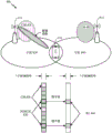
Fig. 8 shows an example of a UE 820 (e.g., UE 120) located in a region where a cell radius of a cell 830 (e.g., a primary cell) overlaps a cell radius of a cell 840 (e.g., a neighboring cell). As shown in fig. 8, UE 820 may receive CSI-RS from BS 810 (e.g., BA 110) in cell 830 and CSI-RS (e.g., a-CSI-RS) from BS 812 (e.g., BS 110) in cell 840. In addition, the UE 820 may receive data/control information from the BS 810 through the PDSCH. However, in the NR standard, the PDSCH is beamformed through a large number of antennas, and the CSI-RS is transmitted without beamforming. As a result, the signal strength associated with PDSCH Resource Elements (REs) is higher than the signal strength associated with CSI-RS REs.
Thus, in the embodiment of fig. 8, if REs of PDSCH in cell 830 collide with REs of non-precoded CSI-RS (e.g., non-zero power (NZP) CSI-RS) in cell 840, a cell-edge UE (e.g., UE 820) may not be able to estimate Reference Signal Received Power (RSRP) on CSI-RS detected in cell 840. Failure of the cell-edge UE to estimate RSRP may result in sending inaccurate CSI feedback, and in some cases, UE 820 performing a Ping-pong (Ping-pong) handover between cell 830 and cell 840 based on the CSI-RSRP. In embodiments described herein, NZP CSI-RS refers to CSI-RS transmitted in, for example, a neighboring cell (e.g., cell 840) that may cause interference to edge UEs (e.g., UE 820) when REs (e.g., REs 860) on which the NZP CSI-RS is transmitted collide with REs of, for example, a PDSCH (e.g., PDSCH850) in a serving cell (e.g., cell 830). Additionally, in embodiments described herein, ZP CSI-RS refers to a Rate Matching Resource (RMR) for configuring a UE to perform PDSCH rate matching around NZP CSI-RS. In some embodiments, the ZP CSI-RS may be transmitted by the serving cell (e.g., cell 830) to the UE.
Thus, certain embodiments discussed herein relate to configuring a UE (e.g., UE120, UE 820, etc.) to perform PDSCH rate matching around NZP CSI-RSs in neighboring cells in order to enable the UE to accurately estimate RSRP on CSI-RSs detected from cells other than the cell transmitting the PDSCH.
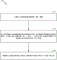
Fig. 9 illustrates example operations for wireless communications by a wireless device in accordance with aspects of the present disclosure. In some embodiments, the wireless device may be a UE. At 902, the operations 900 begin by: a Rate Matching Resource (RMR) configuration is received from a serving cell. At 904, operation 900 continues by: identifying one or more first Resource Elements (REs) to rate match around based at least in part on a transmission number scheme associated with the RMR configuration, wherein the one or more first REs are used for Reference Signal (RS) transmission in a serving cell or a neighboring cell. At 906, operation 900 continues by: mapping a Physical Downlink Shared Channel (PDSCH) to one or more second REs that do not include the first REs.
Fig. 9A illustrates a wireless communication device 900A, which may include various components (e.g., corresponding to elements plus functional components) configured to perform operations for the techniques disclosed herein, such as one or more of the operations illustrated in fig. 9. The communication device 900A includes a processing system 914 coupled to a transceiver 912. The transceiver 912 is configured to transmit and receive signals for the communication device 900A via the antenna 913. The processing system 914 may be configured to perform processing functions for the communication device 900A, such as processing signals and the like.
The processing system 914 includes a processor 909 coupled to a computer-readable medium/memory 911 via a bus 921. In certain aspects, the computer-readable medium/memory 911 is configured to store instructions that, when executed by the processor 909, cause the processor 909 to perform one or more of the operations shown in fig. 9 or other operations for performing the various techniques discussed herein.
In certain aspects, the processing system 914 further includes a receiving component 920 for performing one or more of the operations shown at 902 in fig. 9. Additionally, processing system 914 includes an identification component 922 for performing one or more of the operations shown at 904 in fig. 9. Further, the processing system 914 includes a mapping component 924 for performing one or more of the operations shown at 906 in fig. 9.
The receiving component 920, receiving component 922, identifying component 924, and mapping component 926 may be coupled to the processor 909 via a bus 921. In certain aspects, the receiving component 920, the receiving component 922, the identifying component 924, and the mapping component 926 may be hardware circuitry. In certain aspects, the receiving component 920, the receiving component 922, the identifying component 924, and the mapping component 926 may be software components that execute and run on the processor 909.
As described above, PDSCH rate matching may be performed by the UE around NZP CSI-RSs detected from cells (e.g., cell 840 of fig. 8) other than the cell (e.g., cell 830 of fig. 8) transmitting the PDSCH.
In some embodiments, both cells may use the same numerical scheme. For example, cell 830 and cell 840 of fig. 8 may, for example, use the same kind of subcarrier spacing, slot format, symbol duration, etc. In such embodiments, the UE (e.g., UE 830, UE 120) may receive a Rate Matching (RMR) configuration including Zero Power (ZP) CSI-RS resources from the cell 830 (e.g., serving cell) that configures the UE for performing PDSCH rate matching. In some embodiments, the configuration may be semi-static for the case where the UE receives a periodic or semi-persistent NZP CSI-RS in a neighboring cell (e.g., cell 840 of fig. 8). In some embodiments, the UE may be configured with a dynamic indication for the case where the UE receives an aperiodic NZP CSI-RS in a neighboring cell.
In some embodiments, the ZP CSI-RS may be configured via a CSI framework. In some embodiments, the CSI-RS transmit power may be a parameter in the RS setting, the set of CSI-RS resources, and/or the CSI-RS resources. In such embodiments, the CSI-RS transmit power parameter may comprise at least a zero value. For example, in some embodiments, the transmit power parameter may be 1 bit to indicate ZP as opposed to NZP, or in some embodiments, the transmit power parameter may be multiple bits to indicate multiple NZP levels.
In some embodiments, the CSI-RS resource may inherit the transmit power attribute from the parent RS setting. For example, if the RS setting is configured as ZP, all CSI-RS resource sets and/or CSI-RS resources associated therewith are ZP by default. In another example, if the set of CSI-RS resources is configured as a ZP, all CSI-RS resources associated therewith are ZP by default. In some embodiments, for an individual set of CSI-RS resources or CSI-RS resources, the non-zero CSI-RS transmit power may be further configured as a parameter of the set of CSI-RS resources or CSI-RS resources to cover the ZP setting of its parent RS setting.
In some embodiments, the cells may use different numerologies. Fig. 10 shows an example of a cell 1030 that uses a larger subcarrier spacing (SCS) compared to cell 1040 and also uses a longer symbol duration. For example, as shown in FIG. 8, cell 1030 has a SCS of 15kHz, while cell 1040 has a SCS of 30 kHz. In such embodiments, the numerical scheme of cell 1040 may be transparent to cell 1030. Accordingly, UEs in cell 1030 may be configured with ZP CSI-RSs (e.g., ZP CSI-RS 1050 and ZP CSI-RS1055) using the same transmission number scheme in cell 1030. In some embodiments, a ZP CSI-RS set may be configured, where each ZP CSI-RS may be associated with a different RB comb. This is to match the CSI-RS sets or resources (e.g., NZP CSI-RS 1060 and NZP CSI-RS 1070) of cell 1040. As one example, in some embodiments, for a dynamic ZP CSI-RS indication, a ZP CSI-RS set may be indicated. In one example of such an embodiment, one ZP RS setting or set of ZP CSI-RS resources may be indicated. In another example, 4 ZP CSI-RS resource sets may be semi-statically configured and 1 of the 4 sets may be dynamically indicated by 2 bits in the DCI. In such an example, each set may include several CSI-RSs configured via the CSI framework. For example, the CSI-RS configured in the CSI framework may not be a ZP.
Another example of a cell using a different numerology is shown in fig. 11, where cell 1130 is using a smaller SCS as compared to cell 1140. In such embodiments, the UEs in cell 1130 may be configured with ZP CSI-RS using the same transmission number scheme in cell 1130. In some embodiments, a set of ZP CSI-RSs may be configured, where each ZP CSI-RS is associated with a different time slot. For example, as shown in fig. 11, ZP CSI- RSs 1150 and 1152 are associated with one slot (including 14 symbols), and ZP CSI- RSs 1154 and 1156 are associated with the next slot (including 14 symbols). In such embodiments, each ZP CSI-RS resource may be configured to have a higher density compared to the NZP CSI-RS. In some embodiments, the ZP CSI-RS may be configured to have a different transmission number scheme than the transmission number scheme used for the PDSCH. In some embodiments, the ZP CSI-RS configuration may include parameters to indicate SCS (e.g., 15kHz), while the transmission digital scheme (e.g., 30kHz SCS) is configured separately for PDSCH and NZP CSI-RS (e.g., NZP CSI-RS 1160, NZP CSI-RS 1162, etc.). In such an embodiment, the UE identifies REs under SCS at 30kHz that overlap with ZP CSI-RS in SCS at 15 kHz. After identifying these REs, in some embodiments, the UE may assume that the REs are not mapped with PDSCH.
Certain embodiments discussed herein relate to configuring a UE to perform PUSCH rate matching around a Physical Uplink Control Channel (PUCCH) on the Uplink (UL).
Fig. 12 illustrates example operations for wireless communications by a wireless device, in accordance with aspects of the present disclosure. In some embodiments, the wireless device may be a UE. At 1202, the operations 1200 begin by: a Rate Matching Resource (RMR) configuration is received from a serving cell. At 1204, the operations 1200 continue with: identifying one or more first Resource Elements (REs) to be rate matched around for a Physical Uplink Shared Channel (PUSCH) based at least in part on a signaling configuration in an RMR configuration related to a Physical Uplink Control Channel (PUCCH) and a Sounding Reference Signal (SRS). At 1206, the operations 1200 continue by: mapping a Physical Uplink Shared Channel (PUSCH) to one or more second REs that do not include the first RE.
Fig. 12A illustrates a wireless communication device 1200A, which may include various components (e.g., corresponding to elements plus functional components) configured to perform operations for the techniques disclosed herein, such as one or more of the operations illustrated in fig. 12. The communication device 1200A includes a processing system 1214 coupled to a transceiver 1212. The transceiver 1212 is configured to transmit and receive signals for the communication device 1200A via the antenna 1213. The processing system 1214 may be configured to perform processing functions for the communication device 1200A, such as processing signals, etc.
The processing system 1214 includes a processor 1209 coupled to a computer-readable medium/memory 1211 via a bus 1221. In certain aspects, the computer-readable medium/memory 1211 is configured to store instructions that, when executed by the processor 1209, cause the processor 1209 to perform one or more of the operations shown in fig. 12 or other operations for performing the various techniques discussed herein.
In certain aspects, the processing system 1214 further includes a receiving component 1220 for performing one or more of the operations shown at 1202 in fig. 12. In addition, the processing system 1214 includes an identification component 1222 for performing one or more of the operations shown at 1204 in fig. 12. Further, the processing system 1214 includes a mapping component 1224 for performing one or more of the operations shown at 1206 in fig. 12.
The receiving component 1220, receiving component 1222, identifying component 1224, and mapping component 1226 may be coupled to the processor 1209 via a bus 1221. In certain aspects, the receiving component 1220, the receiving component 1222, the identifying component 1224, and the mapping component 1226 may be hardware circuits. In certain aspects, the receiving component 1220, receiving component 1222, identifying component 1224, and mapping component 1226 may be software components executing and running on the processor 1209.
In some embodiments, PUSCH rate matching is performed to enable long PUSCH to avoid long PUCCH. As described above, in some embodiments, the UE may receive an RMR configuration (e.g., which may include ZP CSI-RS) from the serving cell to be configured for performing PUSCH rate matching. Fig. 13A shows a semi-statically configured set of resources (e.g., including location in time and frequency, frequency hopping pattern, etc.) in long PUCCH regions 1302 and 1304 reserved for transmission of long PUCCH within a UL normal burst (UL normal burst).
In some embodiments, the UE may perform semi-static rate matching to allow the long PUSCH to avoid the entire long PUCCH regions 1302 and 1304. The long PUCCH regions 1302 and 1304 are shared by all UEs in the cell (e.g., the long PUCCH region 1302 may be UE-specific or cell-specific configured). PUSCH Resource Element (RE) mapping may avoid REs in long PUCCH regions 1302 and 1304 if the PUSCH resource allocation partially overlaps with the configured long PUCCH regions 1302 and 1304, as described above. This is shown in fig. 13B, where certain resources (e.g., unused resources 1303 and 1305) in regions 1302 and 1304 allocated for long PUCCH remain unused when they are not occupied by long PUCCH. In other words, fig. 13B shows PUSCH RE mapping that avoids all REs in long PUCCH regions 1302 and 1304.
In some other embodiments, the UE may perform dynamic rate matching, enabling the long PUSCH to avoid resources actually used for the long PUCCH in the regions allocated for the long PUCCH (e.g., regions 1302 and 1304). Similar to fig. 13A, fig. 14A also shows a semi-statically configured set of resources (e.g., including location in time and frequency, frequency hopping pattern, etc.) in long PUCCH regions 1402 and 1404 reserved for long PUCCH within UL regular burst 1400. However, unlike fig. 13B, fig. 14B shows resources 1403 and 1405 to be occupied by PUSCH which are not occupied by PUCCH in a region allocated for PUCCH. As described above, since in the embodiment of fig. 14B, dynamic rate matching is performed so that the PUSCH can avoid only the resources actually used by the long PUCCH in the regions 1402 and 1404 allocated for the long PUCCH.
In the embodiment of fig. 14B, in the UL grant, a used (or unused) long PUCCH resource may be indicated in addition to the PUSCH resource allocation. However, in some embodiments, this indication may be omitted if the PUSCH resource allocation does not overlap with the long PUCCH region. In some embodiments, this indication may be combined with a long PUCCH resource indication. For example, the UE may receive an indication of a subset of resources configured for rate matching, where one resource in the subset may be further indicated as a resource for its own long PUCCH transmission in the same slot.
In some embodiments, the UE may perform PUSCH rate matching to avoid signals/channels in the UL common burst. Fig. 15 shows an example symbol 1502 in the UL short duration of a slot. In some embodiments, the UE may perform semi-static rate matching such that the PUSCH may avoid the entire UL short duration. For example, in such embodiments, if there is a long PUSCH, based on the slot format, the UE may not map the long PUSCH to REs in the UL short duration.
In some embodiments, the UE may perform semi-static rate matching such that the PUSCH may avoid resources reserved for the UL short duration. For example, in such embodiments, the UE may not map PUSCH to resources reserved for short PUCCH. For example, fig. 15 shows a bandwidth 1502, the bandwidth 1502 referring to a scheduled bandwidth of a short PUSCH for a first UE. In one example, the UE may not map PUSCH to resources of bandwidth 1502, including resources reserved for short PUSCH. Further, in some embodiments, the UE may not map PUSCH to RE combs reserved for SRS.
In some embodiments, the UE (e.g., the first UE) may perform dynamic rate matching such that the PUSCH may avoid resources that are actually used for other signals/channels. In such embodiments, in the UL grant, the UE (e.g., the first UE) may receive an indication of: with this indication, rate matching may be performed around one or more RE combs due to aperiodic SRS transmission. In some embodiments, this may be performed by configuring/indicating (subband-dependent) ZP SRS resources. For example, fig. 15 shows a subband 1506 that includes resources on which the second UE transmits aperiodic SRS. Such resources are shown as combs 1508. As described above, in some embodiments, in sub-band 1508, the first UE may perform dynamic rate matching such that PUSCH may avoid aperiodic SRS transmission by the second UE. Thus, the short PUSCH of a first UE may be mapped to comb 1510, comb 1510 referring to a resource on which a second UE does not transmit an aperiodic SRS, where comb 1508 is indicated as ZP SRS for the first UE. Note that the short PUSCH of the first UE may be mapped to the rest of the subband 1506. For example, the short PUSCH of the first UE may be mapped to resources 1512 and 1514.
In some embodiments, the UE may perform PUSCH rate matching around the PUCCH, without being limited to long PUCCH or UL common burst PUCCH/SRS. In such embodiments, the rate matching may be precoder dependent. For example, in some embodiments, for UL closed MIMO, the UE may be assigned a UL precoder at the wideband or subband level. In some embodiments, PUSCH rate matching occurs only with the configured precoder. In such embodiments, a PUSCH rate matched set of precoders may be used. As an example, for PUSCH rank 1, the overall precoder assumption includes the set: { p1, p2 …, p8} (e.g., as shown in FIG. 16), from which { p1, p2} may be selected. If a p1 or p2 precoder is selected on a certain subband, rate matching is performed on these subbands.
For example, for PUSCH rank 2, both the first and second layers are rate matched based on the precoder set. In some embodiments, rate matching is not performed for any other precoders not included in the selected set. In some embodiments, the precoder set may be configured via higher layer signaling/semi-static signaling or dynamic signaling. As discussed, fig. 16 shows a UL regular burst 1600 with a UL long burst 1602. Fig. 16 also shows an example set of precoders { p1, p2 …, p8}, where p1 and p2 are selected or assigned and, therefore, rate matching is performed on the corresponding subbands.
In some embodiments, Rate Matching Resources (RMR) may be configured separately for both DL and UL. The configuration may be semi-static or dynamic. In some embodiments, the semi-static configuration may be for a periodic/semi-persistent NZP CSI-RS or long/short PUCCH in a neighboring cell. In some embodiments, the dynamic configuration may be for aperiodic nzp csi-RS or long/short PUCCH in neighboring cells. In some embodiments, the DL rate matching resources may be linked to a plurality of DL CSI-RS resources, where the CSI-RS resources correspond to CSI-RS time/frequency resources of neighboring cells. In some embodiments, the DL rate matching resources may be linked to SS blocks of neighboring cells or even SS blocks or pilot REs of other (radio access technology) RATs (e.g. LTE). In some embodiments, the UL rate matching resources may be linked to UL long/short PUCCH configurations corresponding to long/short PUCCH resource configurations of the neighboring cells. In some embodiments, the activation or deactivation of rate matching resources may be semi-static or dynamic. In some embodiments, each linked resource may be activated or deactivated via a bitmap-like operation.
FIG. 17 shows an example RMR 1706. Fig. 17 illustrates aggregating CSI-RS settings 1702 of one or more neighboring cells and SS block settings 1704 of LTE into RMR 1706. In some embodiments, when aggregating two settings (e.g., 1702 and 1704) within a rate matching resource, the UE performs rate matching on those reference signals. For example, as shown, resources 1708 are rate matched for lte pss/SSS and resources 1710 are rate matched for CSI-RS of one or more neighboring cells.
The methods disclosed herein comprise one or more steps or actions for achieving the described method. The method steps and/or actions may be interchanged with one another without departing from the scope of the claims. In other words, unless a specific order of steps or actions is specified, the order and/or use of specific steps and/or actions may be modified without departing from the scope of the claims.
As used herein, a phrase referring to "at least one of a list of items refers to any combination of those items, including a single member. For example, "at least one of a, b, or c" is intended to encompass any combination of a, b, c, a-b, a-c, b-c, and a-b-c, as well as multiples of the same element (e.g., any other ordering of a, b, and c), a-a-a, a-a-b, a-a-c, a-b-b, a-c-c, b-b-b, b-b-c, c-c, and c-c-c, or a, b, and c).
As used herein, the term "determining" includes a wide variety of actions. For example, "determining" can include calculating, computing, processing, deriving, investigating, looking up (e.g., looking up in a table, a database or another data structure), ascertaining and the like. Further, "determining" can include receiving (e.g., receiving information), accessing (e.g., accessing data in a memory), and so forth. Further, "determining" may include resolving, selecting, establishing, and the like.
The previous description is provided to enable any person skilled in the art to practice the various aspects described herein. Various modifications to these aspects will be readily apparent to those skilled in the art, and the generic principles defined herein may be applied to other aspects. Thus, the claims are not intended to be limited to the aspects shown herein, but is to be accorded the full scope consistent with the language claims, wherein reference to an element in the singular is not intended to mean "one and only one" unless specifically so stated, but rather "one or more. The term "some" means one or more unless explicitly stated otherwise. All structural and functional equivalents to the elements of the various aspects described throughout this disclosure that are known or later come to be known to those of ordinary skill in the art are expressly incorporated herein by reference and are intended to be encompassed by the claims. Moreover, nothing disclosed herein is intended to be dedicated to the public regardless of whether such disclosure is explicitly recited in the claims. No claim element is to be construed in accordance with the provisions of 35u.s.c. § 112 clause 6, unless the element is explicitly recited using the phrase "unit for … …", or in the case of a method claim, the element is recited using the phrase "step for … …".
The various operations of the methods described above may be performed by any suitable means that can perform the respective functions. These units may include various hardware and/or software components and/or modules, including but not limited to: a circuit, an Application Specific Integrated Circuit (ASIC), or a processor. Generally, where there are operations shown in the figures, those operations may have corresponding counterpart units plus functional components with similar numbering.
For example, the means for transmitting and/or the means for receiving may include one or more of: a transmit processor 420, a TX MIMO processor 430, a receive processor 438 or antenna 434 of the base station 110, and/or a transmit processor 464, a TX MIMO processor 466, a receive processor 458 or antenna 452 of the user equipment 120. Further, the means for generating, the means for multiplexing, and/or the means for applying may comprise one or more processors, such as controller/processor 440 of base station 110 and/or controller/processor 480 of user equipment 120.
The various illustrative logical blocks, modules, and circuits described in connection with the disclosure may be implemented or performed with a general purpose processor, a Digital Signal Processor (DSP), an Application Specific Integrated Circuit (ASIC), a Field Programmable Gate Array (FPGA) or other Programmable Logic Device (PLD), discrete gate or transistor logic, discrete hardware components, or any combination thereof designed to perform the functions described herein. A general purpose processor may be a microprocessor, but in the alternative, the processor may be any commercially available processor, controller, microcontroller or state machine. A processor may also be implemented as a combination of computing devices, e.g., a combination of a DSP and a microprocessor, a plurality of microprocessors, one or more microprocessors in conjunction with a DSP core, or any other such configuration.
If implemented in hardware, an example hardware configuration may include a processing system in the wireless node. The processing system may be implemented using a bus architecture. The buses may include any number of interconnecting buses and bridges depending on the specific application of the processing system and the overall design constraints. A bus may connect together various circuits including the processor, the machine-readable medium, and the bus interface. The bus interface may also be used, among other things, to connect a network adapter to the processing system via the bus. The network adapter may be used to implement signal processing functions of the PHY layer. In the case of a user terminal 120 (see fig. 1), a user interface (e.g., keypad, display, mouse, joystick, etc.) may also be connected to the bus. The bus may also connect various other circuits such as timing sources, peripherals, voltage regulators, power management circuits, and the like, which are well known in the art, and therefore, will not be described any further. The processor may be implemented using one or more general and/or special purpose processors. Examples include microprocessors, microcontrollers, DSP processors, and other circuits that can execute software. Those skilled in the art will recognize how best to implement the described functionality for a processing system depending on the particular application and the overall design constraints imposed on the overall system.
If implemented in software, the functions may be stored on or transmitted over as one or more instructions or code on a computer-readable medium. Software shall be construed broadly to mean instructions, data, or any combination thereof, whether referred to as software, firmware, middleware, microcode, hardware description language, or otherwise. Computer-readable media includes both computer storage media and communication media including any medium that facilitates transfer of a computer program from one place to another. The processor may be responsible for managing the bus and general processing, including executing software modules stored on a machine-readable storage medium. A computer readable storage medium may be coupled to the processor such that the processor can read information from, and write information to, the storage medium. In the alternative, the storage medium may be integral to the processor. By way of example, the machine-readable medium may include a transmission line, a carrier wave modulated by data, and/or a computer-readable storage medium separate from the wireless node having instructions stored thereon, all of which may be accessed by the processor through a bus interface. Alternatively or in addition, the machine-readable medium or any portion thereof may be integrated into a processor, for example, which may be a cache and/or a general register file. Examples of a machine-readable storage medium may include, by way of example, RAM (random access memory), flash memory, ROM (read only memory), PROM (programmable read only memory), EPROM (erasable programmable read only memory), EEPROM (electrically erasable programmable read only memory), registers, a magnetic disk, an optical disk, a hard drive, or any other suitable storage medium, or any combination thereof. The machine-readable medium may be embodied in a computer program product.
A software module may comprise a single instruction, or many instructions, and may be distributed over several different code segments, among different programs, and across multiple storage media. The computer readable medium may include a plurality of software modules. The software modules include instructions that, when executed by an apparatus, such as a processor, cause a processing system to perform various functions. The software modules may include a sending module and a receiving module. Each software module may be located in a single storage device or distributed across multiple storage devices. For example, when a triggering event occurs, a software module may be loaded from the hard drive into RAM. During execution of the software module, the processor may load some of the instructions into the cache to increase access speed. One or more cache lines may then be loaded into the general register file for execution by the processor. It will be understood that when reference is made below to the functionality of a software module, such functionality is achieved by the processor when executing instructions from the software module.
Also, any connection is properly termed a computer-readable medium. For example, if the software is transmitted from a website, server, or other remote source using a coaxial cable, fiber optic cable, twisted pair, Digital Subscriber Line (DSL), or wireless technologies such as Infrared (IR), radio, and microwave, then the coaxial cable, fiber optic cable, twisted pair, DSL, or wireless technologies such as infrared, radio, and microwave are included in the definition of medium. Disk (disk) and disc (disc), as used herein, includes Compact Disc (CD), laser disc, optical disc, Digital Versatile Disc (DVD), floppy disk and optical disks, where disks usually reproduce data magnetically, while optical disks reproduce data optically with lasers. Thus, in some aspects, computer-readable media may comprise non-transitory computer-readable media (e.g., tangible media). Additionally, for other aspects, the computer-readable medium may comprise a non-transitory computer-readable medium (e.g., a signal). Combinations of the above should also be included within the scope of computer-readable media.
Accordingly, certain aspects may comprise a computer program product for performing the operations presented herein. For example, such a computer program product may include a computer-readable medium having instructions stored (and/or encoded) thereon, the instructions being executable by one or more processors to perform the operations described herein.
Further, it should be appreciated that modules and/or other suitable means for performing the methods and techniques described herein can be downloaded and/or otherwise obtained by a user terminal and/or base station as applicable. For example, such a device may be coupled to a server to facilitate communicating means for performing the methods described herein. Alternatively, various methods described herein can be provided via a storage unit (e.g., RAM, ROM, a physical storage medium such as a Compact Disc (CD) or floppy disk, etc.), such that a user terminal and/or base station can obtain the various methods upon coupling or providing the storage unit to the device. Further, any other suitable technique for providing the methods and techniques described herein to a device may be used.
It is to be understood that the claims are not limited to the precise configuration and components shown above. Various modifications, changes and variations may be made in the arrangement, operation and details of the methods and apparatus described above without departing from the scope of the claims.
Claims (32)
1. A method of wireless communication by a User Equipment (UE), comprising:
receiving a Rate Matching Resource (RMR) configuration from a serving cell;
identifying one or more first Resource Elements (REs) to rate match around based at least in part on a transmission number scheme associated with the RMR configuration, wherein the one or more first REs are used for Reference Signal (RS) transmission in the serving cell or a neighboring cell; and
mapping a Physical Downlink Shared Channel (PDSCH) to one or more second REs that do not include the first REs.
2. The method of claim 1, wherein the transmission number scheme associated with the RMR configuration received from the serving cell is the same as a transmission number scheme of the neighboring cell.
3. The method of claim 1, wherein the transmission number scheme associated with the RMR configuration received from the serving cell is different from a transmission number scheme of the neighboring cell.
4. The method of claim 3, wherein a subcarrier spacing corresponding to the transmission digital scheme associated with the RMR configuration received from the serving cell is greater than a subcarrier spacing corresponding to the transmission digital scheme of the neighboring cell.
5. The method of claim 3, wherein a subcarrier spacing corresponding to the transmission digital scheme associated with the RMR configuration received from the serving cell is less than a subcarrier spacing corresponding to the transmission digital scheme of the neighboring cell.
6. The method of claim 1, wherein the RMR comprises a zero-power channel state information reference signal (zpccsi-RS).
7. A method of wireless communication by a User Equipment (UE), comprising:
receiving a Rate Matching Resource (RMR) configuration from a serving cell;
identifying one or more first Resource Elements (REs) to be rate matched around for a Physical Uplink Shared Channel (PUSCH) based at least in part on a signaling configuration in the RMR configuration related to a Physical Uplink Control Channel (PUCCH) and a Sounding Reference Signal (SRS); and
mapping a Physical Uplink Shared Channel (PUSCH) to one or more second REs that do not include the first RE.
8. The method of claim 7, wherein the one or more first REs are designated for uplink long PUCCH transmission in the serving cell or a neighboring cell.
9. The method of claim 7, wherein the one or more first REs are used for uplink long PUCCH transmission in the serving or neighboring cell.
10. The method of claim 7, wherein the one or more first REs correspond to an uplink short duration in the serving cell or a neighboring cell.
11. The method of claim 7, wherein the one or more first REs are reserved for uplink short PUCCH and SRS transmission in an uplink short duration in the serving or neighboring cell.
12. The method of claim 7, wherein the one or more first REs are used for transmitting signals or channels including an uplink short PUCCH and SRS in an uplink short duration in the serving or neighboring cell.
13. The method of claim 7, wherein the identifying is further based on an uplink multiple-input multiple-output (MIMO) precoder in the RMR configuration.
14. The method of claim 7, wherein the RMR comprises a zero-power channel state information reference signal (zpccsi-RS).
15. An apparatus, comprising:
a non-transitory memory comprising executable instructions; and
a processor in data communication with the memory and configured to execute the instructions to cause the apparatus to:
receiving a Rate Matching Resource (RMR) configuration from a serving cell;
identifying one or more first Resource Elements (REs) to rate match around based at least in part on a transmission number scheme associated with the RMR configuration, wherein the one or more first REs are used for Reference Signal (RS) transmission in the serving cell or a neighboring cell; and
mapping a Physical Downlink Shared Channel (PDSCH) to one or more second REs that do not include the first REs.
16. The apparatus of claim 15, wherein the transmission number scheme associated with the RMR configuration received from the serving cell is the same as a transmission number scheme of the neighboring cell.
17. The apparatus of claim 15, wherein the transmission number scheme associated with the RMR configuration received from the serving cell is different from a transmission number scheme of the neighboring cell.
18. The apparatus of claim 17, wherein a subcarrier spacing corresponding to the transmission digital scheme associated with the RMR configuration received from the serving cell is greater than a subcarrier spacing corresponding to the transmission digital scheme of the neighboring cell.
19. The apparatus of claim 17, wherein a subcarrier spacing corresponding to the transmission digital scheme associated with the RMR configuration received from the serving cell is less than a subcarrier spacing corresponding to the transmission digital scheme of the neighboring cell.
20. The apparatus of claim 15, wherein the RMR comprises a zero-power channel state information reference signal (zpccsi-RS).
21. An apparatus, comprising:
a non-transitory memory comprising executable instructions; and
a processor in data communication with the memory and configured to execute the instructions to cause the apparatus to:
receiving a Rate Matching Resource (RMR) configuration from a serving cell;
identifying one or more first Resource Elements (REs) to be rate matched around for a Physical Uplink Shared Channel (PUSCH) based at least in part on a signaling configuration in the RMR configuration related to a Physical Uplink Control Channel (PUCCH) and a Sounding Reference Signal (SRS); and
mapping a Physical Uplink Shared Channel (PUSCH) to one or more second REs that do not include the first RE.
22. The apparatus of claim 21, wherein the one or more first REs are designated for uplink long PUCCH transmission in the serving or neighboring cell.
23. The apparatus of claim 21, wherein the one or more first REs are used for uplink long PUCCH transmission in the serving or neighboring cell.
24. The apparatus of claim 21, wherein the one or more first REs correspond to an uplink short duration in the serving cell or a neighboring cell.
25. The apparatus of claim 21, wherein the one or more first REs are reserved for uplink short PUCCH and SRS transmissions in an uplink short duration in the serving or neighboring cell.
26. The apparatus of claim 21, wherein the one or more first REs are used for transmission of signals or channels comprising an uplink short PUCCH and SRS in an uplink short duration in the serving or neighboring cell.
27. The apparatus of claim 21, wherein the identifying is further based on an uplink multiple-input multiple-output (MIMO) precoder in the RMR configuration.
28. The apparatus of claim 21, wherein the RMR comprises a zero-power channel state information reference signal (zpccsi-RS).
29. An apparatus for wireless communication, comprising:
means for receiving a Rate Matching Resource (RMR) configuration from a serving cell;
means for identifying one or more first Resource Elements (REs) to rate match around based at least in part on a transmission number scheme associated with the RMR configuration, wherein the one or more first REs are used for Reference Signal (RS) transmission in the serving cell or a neighboring cell; and
means for mapping a Physical Downlink Shared Channel (PDSCH) to one or more second REs that do not include the first RE.
30. An apparatus for wireless communication, comprising:
means for receiving a Rate Matching Resource (RMR) configuration from a serving cell;
means for identifying one or more first Resource Elements (REs) to be rate matched around for a Physical Uplink Shared Channel (PUSCH) based at least in part on a signaling configuration in the RMR configuration related to a Physical Uplink Control Channel (PUCCH) and a Sounding Reference Signal (SRS); and
means for mapping a Physical Uplink Shared Channel (PUSCH) to one or more second REs that do not include the first RE.
31. A non-transitory computer-readable medium having instructions stored thereon, which when executed by a User Equipment (UE) cause the UE to perform a method comprising:
receiving a Rate Matching Resource (RMR) configuration from a serving cell;
identifying one or more first Resource Elements (REs) to rate match around based at least in part on a transmission number scheme associated with the RMR configuration, wherein the one or more first REs are used for Reference Signal (RS) transmission in the serving cell or a neighboring cell; and
mapping a Physical Downlink Shared Channel (PDSCH) to one or more second REs that do not include the first REs.
32. A non-transitory computer-readable medium having instructions stored thereon, which when executed by a User Equipment (UE) cause the UE to perform a method comprising:
receiving a Rate Matching Resource (RMR) configuration from a serving cell;
identifying one or more first Resource Elements (REs) to be rate matched around for a Physical Uplink Shared Channel (PUSCH) based at least in part on a signaling configuration in the RMR configuration related to a Physical Uplink Control Channel (PUCCH) and a Sounding Reference Signal (SRS); and
mapping a Physical Uplink Shared Channel (PUSCH) to one or more second REs that do not include the first RE.
Applications Claiming Priority (3)
| Application Number | Priority Date | Filing Date | Title |
|---|---|---|---|
| PCT/CN2017/104081 WO2019061190A1 (en) | 2017-09-28 | 2017-09-28 | Rate matching for new radio (nr) physical downlink shared channel (pdsch) and physical uplink shared channel (pusch) |
| CNPCT/CN2017/104081 | 2017-09-28 | ||
| PCT/CN2018/107403 WO2019062726A1 (en) | 2017-09-28 | 2018-09-25 | Rate matching for new radio (nr) physical downlink shared channel (pdsch) and physical uplink shared channel (pusch) |
Publications (1)
| Publication Number | Publication Date |
|---|---|
| CN111133821A true CN111133821A (en) | 2020-05-08 |
Family
ID=65900212
Family Applications (1)
| Application Number | Title | Priority Date | Filing Date |
|---|---|---|---|
| CN201880061742.1A Pending CN111133821A (en) | 2017-09-28 | 2018-09-25 | Rate matching for New Radio (NR) Physical Downlink Shared Channel (PDSCH) and Physical Uplink Shared Channel (PUSCH) |
Country Status (8)
| Country | Link |
|---|---|
| US (1) | US20200295895A1 (en) |
| EP (1) | EP3689066A4 (en) |
| JP (1) | JP7233417B2 (en) |
| KR (1) | KR20200063144A (en) |
| CN (1) | CN111133821A (en) |
| BR (1) | BR112020005724A2 (en) |
| CA (1) | CA3073788A1 (en) |
| WO (2) | WO2019061190A1 (en) |
Cited By (1)
| Publication number | Priority date | Publication date | Assignee | Title |
|---|---|---|---|---|
| CN115486158A (en) * | 2020-05-13 | 2022-12-16 | 高通股份有限公司 | Collision handling for sounding reference signal guard period and physical uplink shared channel transmission |
Families Citing this family (4)
| Publication number | Priority date | Publication date | Assignee | Title |
|---|---|---|---|---|
| CN110431895B (en) * | 2017-03-24 | 2023-05-23 | 松下电器(美国)知识产权公司 | Resource sharing between different OFDM parameter sets |
| CN111836377B (en) * | 2019-08-12 | 2023-09-22 | 维沃移动通信有限公司 | Scheduling method, network equipment and terminal |
| CN112449423A (en) * | 2019-08-30 | 2021-03-05 | 上海华为技术有限公司 | Data interaction method |
| WO2024060266A1 (en) * | 2022-09-24 | 2024-03-28 | Qualcomm Incorporated | Use of lp-rs for measurements in dormant states |
Citations (4)
| Publication number | Priority date | Publication date | Assignee | Title |
|---|---|---|---|---|
| WO2014032508A1 (en) * | 2012-08-29 | 2014-03-06 | 中兴通讯股份有限公司 | Downlink data rate-matching method and device |
| CN105706385A (en) * | 2014-03-07 | 2016-06-22 | Lg电子株式会社 | Method for receiving discovery reference signal by terminal in wireless communication system and device therefor |
| WO2017126946A1 (en) * | 2016-01-21 | 2017-07-27 | 엘지전자(주) | Uplink transmission method in wireless communication system and device therefor |
| CN107005374A (en) * | 2014-12-08 | 2017-08-01 | Lg 电子株式会社 | Send the method and its equipment of uplink control information |
Family Cites Families (21)
| Publication number | Priority date | Publication date | Assignee | Title |
|---|---|---|---|---|
| CN102017445B (en) * | 2007-01-05 | 2014-05-07 | Lg电子株式会社 | Layer mapping method and data transmission method for MIMO system |
| US8917796B1 (en) * | 2009-10-19 | 2014-12-23 | Marvell International Ltd. | Transmission-mode-aware rate matching in MIMO signal generation |
| US8743799B2 (en) * | 2010-06-24 | 2014-06-03 | Nokia Siemens Networks Oy | Change of rate matching modes in presence of channel state information reference signal transmission |
| CN104737479B (en) * | 2012-10-18 | 2018-07-06 | Lg电子株式会社 | The method and apparatus of downlink control signal is received or sent in communication system |
| GB2512653B (en) * | 2013-04-05 | 2018-04-11 | Broadcom Corp | Interference mitigation |
| CN104105120B (en) * | 2013-04-08 | 2019-03-12 | 中兴通讯股份有限公司 | A kind of interference detecting method, network side equipment and terminal device |
| KR102199693B1 (en) * | 2013-11-01 | 2021-01-07 | 후아웨이 테크놀러지 컴퍼니 리미티드 | Apparatus and Method for Cancelling Inter-cell Interference in Wireless Communication System |
| CN105007600A (en) * | 2014-04-15 | 2015-10-28 | 中兴通讯股份有限公司 | Downlink data rate matching method and apparatus |
| EP3149878B1 (en) * | 2014-05-28 | 2018-08-29 | Sony Corporation | Communications device, infrastructure equipment and methods for lte communication within unused gsm channels |
| KR102045971B1 (en) * | 2016-04-20 | 2019-11-18 | 엘지전자 주식회사 | A method for connecting to a base station with flexible bandwidth |
| US10660081B2 (en) * | 2016-06-01 | 2020-05-19 | Lg Electronics Inc. | Downlink signal reception method and user equipment, and downlink signal transmission method and base station |
| EP3487213B1 (en) * | 2016-07-15 | 2022-03-30 | Ntt Docomo, Inc. | User terminal, radio base station and radio communication method for receiving downlink shared channel |
| JP6968837B2 (en) * | 2016-09-05 | 2021-11-17 | オッポ広東移動通信有限公司Guangdong Oppo Mobile Telecommunications Corp., Ltd. | Reference signal transmission method, network equipment and terminal equipment |
| DK3520510T3 (en) * | 2016-09-30 | 2022-06-07 | Ericsson Telefon Ab L M | Autonomous time adjustment for a wireless device |
| US10334533B2 (en) * | 2016-11-02 | 2019-06-25 | At&T Intellectual Property I, L.P. | Non-orthogonal design for channel state information reference signals for a 5G air interface or other next generation network interfaces |
| US10856317B2 (en) * | 2016-11-17 | 2020-12-01 | Huawei Technologies Co., Ltd. | System and method for uplink communications |
| US10237032B2 (en) * | 2017-01-06 | 2019-03-19 | At&T Intellectual Property I, L.P. | Adaptive channel state information reference signal configurations for a 5G wireless communication network or other next generation network |
| WO2018212619A1 (en) * | 2017-05-19 | 2018-11-22 | Samsung Electronics Co., Ltd. | Method and apparatus for reduction of csi-rs transmission overhead in wireless communication system |
| US10911291B2 (en) * | 2017-06-16 | 2021-02-02 | Lg Electronics Inc. | Method and apparatus for transmitting and receiving downlink channel |
| US11324047B2 (en) * | 2017-11-10 | 2022-05-03 | Qualcomm Incorporated | NR-unlicensed transmission opportunity structure with flexible starting point |
| US10897755B2 (en) * | 2017-12-22 | 2021-01-19 | Samsung Electronics Co., Ltd | Method and apparatus for configuring demodulation reference signal information in wireless cellular communication system |
-
2017
- 2017-09-28 WO PCT/CN2017/104081 patent/WO2019061190A1/en active Application Filing
-
2018
- 2018-09-25 EP EP18860568.7A patent/EP3689066A4/en active Pending
- 2018-09-25 WO PCT/CN2018/107403 patent/WO2019062726A1/en unknown
- 2018-09-25 JP JP2020517595A patent/JP7233417B2/en active Active
- 2018-09-25 KR KR1020207008497A patent/KR20200063144A/en not_active Application Discontinuation
- 2018-09-25 BR BR112020005724-0A patent/BR112020005724A2/en unknown
- 2018-09-25 CN CN201880061742.1A patent/CN111133821A/en active Pending
- 2018-09-25 CA CA3073788A patent/CA3073788A1/en active Pending
- 2018-09-28 US US16/650,056 patent/US20200295895A1/en active Pending
Patent Citations (4)
| Publication number | Priority date | Publication date | Assignee | Title |
|---|---|---|---|---|
| WO2014032508A1 (en) * | 2012-08-29 | 2014-03-06 | 中兴通讯股份有限公司 | Downlink data rate-matching method and device |
| CN105706385A (en) * | 2014-03-07 | 2016-06-22 | Lg电子株式会社 | Method for receiving discovery reference signal by terminal in wireless communication system and device therefor |
| CN107005374A (en) * | 2014-12-08 | 2017-08-01 | Lg 电子株式会社 | Send the method and its equipment of uplink control information |
| WO2017126946A1 (en) * | 2016-01-21 | 2017-07-27 | 엘지전자(주) | Uplink transmission method in wireless communication system and device therefor |
Non-Patent Citations (3)
| Title |
|---|
| AT&T: "Design and Evaluation of CSI-RS for NR MIMO with Mixed Numerology Support" * |
| HUAWEI等: "Rate Matching for data channels" * |
| LG ELECTRONICS: "Considerations on UCI and UL channel multiplexing for NR" * |
Cited By (1)
| Publication number | Priority date | Publication date | Assignee | Title |
|---|---|---|---|---|
| CN115486158A (en) * | 2020-05-13 | 2022-12-16 | 高通股份有限公司 | Collision handling for sounding reference signal guard period and physical uplink shared channel transmission |
Also Published As
| Publication number | Publication date |
|---|---|
| JP7233417B2 (en) | 2023-03-06 |
| KR20200063144A (en) | 2020-06-04 |
| EP3689066A1 (en) | 2020-08-05 |
| EP3689066A4 (en) | 2021-09-01 |
| WO2019061190A1 (en) | 2019-04-04 |
| WO2019062726A1 (en) | 2019-04-04 |
| CA3073788A1 (en) | 2019-04-04 |
| JP2020535740A (en) | 2020-12-03 |
| BR112020005724A2 (en) | 2020-10-20 |
| US20200295895A1 (en) | 2020-09-17 |
Similar Documents
| Publication | Publication Date | Title |
|---|---|---|
| US11677533B2 (en) | Methods and apparatus for setting subband CSI-related parameters | |
| CN110089180B (en) | Transmitting sounding reference signals in a new radio | |
| CN112753169A (en) | System and method for reporting beam correspondence status | |
| CN111052786A (en) | Method for configuring non-codebook based UL MIMO transmissions | |
| WO2018165911A1 (en) | Method for indicating pdsch/pusch resource element mapping | |
| CN109937597B (en) | UE assisted physical resource block group (PRG) configuration and signaling | |
| CN112655157B (en) | CSI reporting configuration with codebook list | |
| CN111095977A (en) | Method and apparatus for CSI-RS port subset indication | |
| EP3665784B1 (en) | Precoding reference signals for uplink transmission with downlink interference information | |
| CN110506447B (en) | Scheduling request multiplexing based on reliability and delay objectives | |
| JP7233417B2 (en) | Rate matching for new radio (NR) physical downlink shared channel (PDSCH) and physical uplink shared channel (PUSCH) | |
| US11863479B2 (en) | Quasi-colocation indication for demodulation reference signals | |
| CN110945818A (en) | Multiplexing demodulation reference signals and synchronization signals in new radios | |
| CN112272930A (en) | Spatial multiplexing of Physical Uplink Control Channel (PUCCH) and Sounding Reference Signal (SRS) | |
| CN112840587A (en) | Quasi-co-location indication for non-zero power csi-rs port set | |
| CN111357374A (en) | Efficient data scheduling with supplemental uplink carriers | |
| CN113228551A (en) | Channel state feedback calculation and beam training for full duplex communication | |
| CN110892665A (en) | Physical Uplink Control Channel (PUCCH) sequence configuration | |
| CN110268669B (en) | Method and device for determining transmission resource index of binding channel in special subframe |
Legal Events
| Date | Code | Title | Description |
|---|---|---|---|
| PB01 | Publication | ||
| PB01 | Publication | ||
| SE01 | Entry into force of request for substantive examination | ||
| SE01 | Entry into force of request for substantive examination | ||
| REG | Reference to a national code |
Ref country code: HK Ref legal event code: DE Ref document number: 40028690 Country of ref document: HK |