CN111076639A - Inner circle jumping gauge - Google Patents
Inner circle jumping gauge Download PDFInfo
- Publication number
- CN111076639A CN111076639A CN202010098801.1A CN202010098801A CN111076639A CN 111076639 A CN111076639 A CN 111076639A CN 202010098801 A CN202010098801 A CN 202010098801A CN 111076639 A CN111076639 A CN 111076639A
- Authority
- CN
- China
- Prior art keywords
- lever
- rotating shaft
- seat
- taper sleeve
- sleeve
- Prior art date
- Legal status (The legal status is an assumption and is not a legal conclusion. Google has not performed a legal analysis and makes no representation as to the accuracy of the status listed.)
- Pending
Links
Images


Classifications
-
- G—PHYSICS
- G01—MEASURING; TESTING
- G01B—MEASURING LENGTH, THICKNESS OR SIMILAR LINEAR DIMENSIONS; MEASURING ANGLES; MEASURING AREAS; MEASURING IRREGULARITIES OF SURFACES OR CONTOURS
- G01B5/00—Measuring arrangements characterised by the use of mechanical techniques
Abstract
The invention relates to an inner circle run-out gauge which comprises a rotating seat, a lever, a gauge and a clearance eliminating mechanism, wherein the upper end surface of the rotating seat is fixedly provided with a lever seat, the middle part of the lever is rotatably arranged in a through hole through a rotating shaft, and a tension spring is also arranged between the gauge seat and the lever; the clearance eliminating mechanism comprises a taper sleeve, balls and a pre-tightening adjusting sleeve, wherein concave conical surfaces are arranged at two ends of the taper sleeve, the taper sleeve is arranged between a rotating shaft and a lever, the conical surfaces at two ends of the taper sleeve are respectively provided with the balls, a shaft shoulder is abutted to the balls in the conical surface at one end of the taper sleeve, the pre-tightening adjusting sleeve is further sleeved on the rotating shaft, one end of the pre-tightening adjusting sleeve is abutted to the balls in the conical surface at the other end of the taper sleeve, a gasket is sleeved on the rotating shaft, and the gasket is abutted to the other end of the pre-tightening adjusting sleeve and locked by. According to the invention, the gap between the lever and the rotating shaft is eliminated through the ball and the taper sleeve, so that the lever can bear larger force along the axial direction of the rotating shaft, the lever cannot swing in the axial direction of the rotating shaft, and the measurement stability is high.
Description
Technical Field
The invention relates to the technical field of detection tools, in particular to an inner circle run-out detection tool.
Background
Circle run-out (circle run-out) refers to the difference between the maximum and minimum readings measured by a fixed position indicator in a given direction as the workpiece being measured makes one revolution about a reference axis.
During the production of the component, the value of the circular run-out is often detected. The existing circular runout checking fixture adopts a rotating shaft and a lever to form matching, one end of the lever is abutted to the inner wall of a workpiece to be measured, the other end of the lever measures the swing value of the lever through a meter, in order to enable the lever to freely rotate, the rotating shaft and the lever are in clearance fit, in the rotation detection process of the checking fixture, the lever is subjected to the force of the inner wall of the workpiece to be measured, the lever swings in the axis direction of the rotating shaft, and finally, a large measurement error occurs.
Disclosure of Invention
The invention aims to overcome the defects in the prior art and provides an inner circle run-out gauge.
The purpose of the invention is realized by the following technical scheme:
an inner circle runout gauge comprises a rotating seat, a lever, a gauge and a gap eliminating mechanism, wherein the rotating seat is of a cylindrical structure, a through groove is formed in the outer wall of the rotating seat along the axial direction, a lever seat is fixed on the upper end face of the rotating seat, a through hole is formed in the lever seat, the middle of the lever is rotatably installed in the through hole through a rotating shaft, the lower end of the lever extends into the through groove, a ball head contact block is fixed at the lower end of the lever, a butt block is fixed at the upper end of the lever, the gauge seat is fixed on one side of the lever seat, the gauge is clamped and fixed on the gauge seat, a contact of the gauge is in butt joint with the butt block, and a tension spring is further installed between the gauge seat and the lever; the clearance eliminating mechanism comprises a taper sleeve, balls and a pre-tightening adjusting sleeve, wherein concave conical surfaces are arranged at two ends of the taper sleeve, the taper sleeve is arranged between a rotating shaft and a lever, the balls are respectively arranged in conical surfaces at two ends of the taper sleeve, a shaft shoulder is arranged on the rotating shaft, the shaft shoulder abuts against the balls in the conical surface at one end of the taper sleeve, the pre-tightening adjusting sleeve is further sleeved on the rotating shaft, one end of the pre-tightening adjusting sleeve abuts against the balls in the conical surface at the other end of the taper sleeve, an external thread is arranged at one end, away from the shaft shoulder, of the rotating shaft, a gasket is arranged on the end sleeve, and the gasket abuts against the other end of the pre-tightening adjusting sleeve and is locked.
Further, the meter is a dial indicator or a dial indicator.
Further, in a natural state, the ball head end of the ball head contact block extends out of the through groove under the action of the tension spring.
Furthermore, a handle is fixed on the upper end face of the rotating seat.
Furthermore, an interference fit is formed between the outer wall of the taper sleeve and the inner hole of the lever, and a clearance fit is formed between the inner wall of the taper sleeve and the outer wall of the rotating shaft.
Further, the distance between the axis of the abutting block and the axis of the rotating shaft is a, the distance between the axis of the ball head contact block and the axis of the rotating shaft is b, and a = b.
The invention has the following advantages:
the invention adopts an open bearing structure as a clearance eliminating mechanism, and can adjust the position of the pre-tightening adjusting sleeve through the nut, thereby adjusting the abutting force between the ball and the taper sleeve, realizing that the clearance between the lever and the rotating shaft is eliminated through the ball and the taper sleeve, leading the lever to bear larger force along the axial direction of the rotating shaft, leading the lever not to swing in the axial direction of the rotating shaft and having high measurement stability.
Drawings
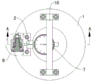
FIG. 1 is a schematic structural view of the present invention;
FIG. 2 is an enlarged view of the structure at B in FIG. 1;
FIG. 3 is a schematic sectional view of A-A in FIG. 1;
FIG. 4 is a schematic illustration of the present invention as it is being measured on a workpiece;
in the figure: 1-rotating seat, 1 a-through groove, 2-gauge seat, 3-lever seat, 3 a-through hole, 4-rotating shaft, 4 a-shaft shoulder, 5-lever, 6-ball head contact block, 7-gauge, 8-butting block, 9-tension spring, 10-lifting handle, 11-taper sleeve, 12-ball, 13-pre-tightening adjusting sleeve, 14-gasket and 15-nut.
Detailed Description
The invention will be further described with reference to the accompanying drawings, but the scope of the invention is not limited to the following.
As shown in fig. 1 to 3, an inner circle run-out gauge comprises a rotating seat 1, a lever 5, a gauge 7 and a gap eliminating mechanism, wherein the rotating seat 1 is of a cylindrical structure, a through groove 1a is formed in the outer wall of the rotating seat 1 along the axial direction, a lever seat 3 is fixed on the upper end surface of the rotating seat 1, a through hole 3a is formed in the lever seat 3, the middle part of the lever 5 is rotatably installed in the through hole 3a through a rotating shaft 4, the lower end of the lever 5 extends into the through groove 1a, a ball head contact block 6 is fixed at the lower end of the lever 5, a butt block 8 is fixed at the upper end of the lever 5, a gauge seat 2 is fixed at one side of the lever seat 3, the gauge 7 is clamped and fixed on the gauge seat 2, a contact of the gauge 7 is in butt joint with the butt block 8, and a tension spring 9 is further installed between the gauge seat 2 and the lever 5; the clearance eliminating mechanism comprises a taper sleeve 11, balls 12 and a pre-tightening adjusting sleeve 13, wherein concave conical surfaces are arranged at two ends of the taper sleeve 11, the taper sleeve 11 is arranged between a rotating shaft 4 and a lever 5, the conical surfaces at two ends of the taper sleeve 11 are respectively provided with the balls 12, a shaft shoulder 4a is arranged on the rotating shaft 4, the shaft shoulder 4a abuts against the balls 12 in the conical surface at one end of the taper sleeve 11, the rotating shaft 4 is further sleeved with the pre-tightening adjusting sleeve 13, one end of the pre-tightening adjusting sleeve 13 abuts against the balls 12 in the conical surface at the other end of the taper sleeve 11, one end, far away from the shaft shoulder 4a, of the rotating shaft 4 is provided with an external thread, a gasket 14 is sleeved at the end, the gasket 14 abuts against the other end of the pre-tightening adjusting sleeve 13, and is locked.
Further, the meter 7 is a dial indicator or a dial indicator, and different measuring meters can be selected according to different measuring accuracies.
Further, in a natural state, the ball end of the ball contact block 6 extends out of the through groove 1a under the action of the pulling force of the tension spring 9, so that the ball end of the ball contact block 6 can be abutted against the inner wall of the workpiece to be measured.
Furthermore, a handle 10 is further fixed on the upper end face of the rotating seat 1, so that the checking fixture can be conveniently rotated.
Furthermore, the outer wall of the taper sleeve 11 is in interference fit with the inner hole of the lever 5, and the inner wall of the taper sleeve 11 is in clearance fit with the outer wall of the rotating shaft 4.
More preferably, the distance between the axis of the abutment block 8 and the axis of the rotating shaft 4 is a, the distance between the axis of the ball head contact block 6 and the axis of the rotating shaft 4 is b, and a = b, so that the measurement can be simplified, namely, the reading of table 7 is the circle run-out value.
The working process of the invention is as follows: as shown in fig. 4, the rotating base 1 of the present invention is placed in the circular groove of the workpiece to be measured, so that the ball end of the ball contact block 6 abuts against the inner wall of the workpiece to be measured, the meter 7 is returned to zero, the handle 10 is held by hand, the rotating base is slowly rotated, the reading change of the meter 7 is observed, and the difference value between the maximum reading and the minimum reading is the circular runout value.
Although embodiments of the present invention have been shown and described, it will be appreciated by those skilled in the art that changes, modifications, substitutions and alterations can be made in these embodiments without departing from the principles and spirit of the invention, the scope of which is defined in the appended claims and their equivalents.
Claims (6)
1. The utility model provides an interior circle is beated and is examined utensil which characterized in that: comprises a rotating seat (1), a lever (5), a watch (7) and a gap eliminating mechanism, the rotating seat (1) is of a cylindrical structure, a through groove (1 a) is formed in the outer wall of the rotating seat (1) along the axial direction, a lever seat (3) is fixed on the upper end surface of the rotating seat (1), a through hole (3 a) is arranged in the lever seat (3), the middle part of the lever (5) is rotatably arranged in the through hole (3 a) through a rotating shaft (4), the lower end of the lever (5) extends into the through groove (1 a), a ball head contact block (6) is fixed at the lower end of the lever (5), the upper end of the lever (5) is fixed with a butt joint block (8), one side of the lever seat (3) is fixed with a meter seat (2), the meter (7) is clamped and fixed on the meter seat (2), the contact of the meter (7) is abutted against the abutting block (8), and a tension spring (9) is further arranged between the meter seat (2) and the lever (5); the clearance eliminating mechanism comprises a taper sleeve (11), balls (12) and a pre-tightening adjusting sleeve (13), concave conical surfaces are arranged at two ends of the taper sleeve (11), the taper sleeve (11) is arranged between a rotating shaft (4) and a lever (5), a plurality of balls (12) are respectively arranged in the conical surfaces at two ends of the taper sleeve (11), a shaft shoulder (4 a) is arranged on the rotating shaft (4), the shaft shoulder (4 a) abuts against the balls (12) in the conical surface at one end of the taper sleeve (11), the pre-tightening adjusting sleeve (13) is further sleeved on the rotating shaft (4), one end of the pre-tightening adjusting sleeve (13) abuts against the balls (12) in the conical surface at the other end of the taper sleeve (11), an external thread is arranged at one end, far away from the shaft shoulder (4 a), of the rotating shaft (4) is provided with a gasket (14), and the gasket (14) abuts against the other end of the pre-tightening adjusting sleeve (13), and then locked by a nut (15).
2. The internal circle run-out gauge according to claim 1, wherein: the gauge (7) is a dial indicator or a dial indicator.
3. The internal circle run-out gauge according to claim 1, wherein: in a natural state, the ball head end of the ball head contact block (6) extends out of the through groove (1 a) under the action of the tension spring (9).
4. The internal circle run-out gauge according to claim 1, wherein: a handle (10) is also fixed on the upper end surface of the rotating seat (1).
5. The internal circle run-out gauge according to claim 1, wherein: be interference fit between the outer wall of taper sleeve (11) and the hole of lever (5), be clearance fit between the inner wall of taper sleeve (11) and the outer wall of pivot (4).
6. The internal circle run-out gauge according to claim 1, wherein: the distance between the axis of the abutting block (8) and the axis of the rotating shaft (4) is a, the distance between the axis of the ball head contact block (6) and the axis of the rotating shaft (4) is b, and a = b.
Priority Applications (1)
| Application Number | Priority Date | Filing Date | Title |
|---|---|---|---|
| CN202010098801.1A CN111076639A (en) | 2020-02-18 | 2020-02-18 | Inner circle jumping gauge |
Applications Claiming Priority (1)
| Application Number | Priority Date | Filing Date | Title |
|---|---|---|---|
| CN202010098801.1A CN111076639A (en) | 2020-02-18 | 2020-02-18 | Inner circle jumping gauge |
Publications (1)
| Publication Number | Publication Date |
|---|---|
| CN111076639A true CN111076639A (en) | 2020-04-28 |
Family
ID=70324494
Family Applications (1)
| Application Number | Title | Priority Date | Filing Date |
|---|---|---|---|
| CN202010098801.1A Pending CN111076639A (en) | 2020-02-18 | 2020-02-18 | Inner circle jumping gauge |
Country Status (1)
| Country | Link |
|---|---|
| CN (1) | CN111076639A (en) |
Cited By (2)
| Publication number | Priority date | Publication date | Assignee | Title |
|---|---|---|---|---|
| CN111707168A (en) * | 2020-06-04 | 2020-09-25 | 湖北亿鹏展精密机械有限公司 | Inner hole size measuring device and measuring method suitable for revolving body part |
| CN112414257A (en) * | 2021-01-14 | 2021-02-26 | 桂林福达重工锻造有限公司 | Crankshaft blank center hole runout testing fixture |
-
2020
- 2020-02-18 CN CN202010098801.1A patent/CN111076639A/en active Pending
Cited By (4)
| Publication number | Priority date | Publication date | Assignee | Title |
|---|---|---|---|---|
| CN111707168A (en) * | 2020-06-04 | 2020-09-25 | 湖北亿鹏展精密机械有限公司 | Inner hole size measuring device and measuring method suitable for revolving body part |
| CN111707168B (en) * | 2020-06-04 | 2021-09-03 | 湖北亿鹏展精密机械有限公司 | Inner hole size measuring device and measuring method suitable for revolving body part |
| CN112414257A (en) * | 2021-01-14 | 2021-02-26 | 桂林福达重工锻造有限公司 | Crankshaft blank center hole runout testing fixture |
| CN112414257B (en) * | 2021-01-14 | 2022-05-06 | 桂林福达重工锻造有限公司 | Crankshaft blank center hole runout testing fixture |
Similar Documents
| Publication | Publication Date | Title |
|---|---|---|
| CN202074915U (en) | High precision testing device of engine valve disk terminal conical face height | |
| CN111076639A (en) | Inner circle jumping gauge | |
| CN202024752U (en) | Coaxiality measuring instrument | |
| CN201444029U (en) | Multifunctional inner hole measuring scale | |
| CN102003931B (en) | Comprehensive detection method and device of tool tapered handle (7:24) | |
| CN207936891U (en) | A kind of instrument for measuring pitch diameter of internal thread | |
| WO2015089689A1 (en) | Micrometer for inner and outer diameter detection | |
| CN105312964A (en) | Detection method and detection device for rotation precision of precision machine tool spindle | |
| CN211120947U (en) | Inner circle jumping gauge | |
| WO2024066605A1 (en) | Height gauge and gauging method for circlip groove of bevel gear | |
| CN112146553A (en) | Inner inclined hole position size measuring device and design and use method thereof | |
| CN209783446U (en) | checking fixture for tooth alignment position of spiral teeth of intermediate shaft | |
| CN205254688U (en) | Precision machine tool main shaft gyration accuracy testing device | |
| CN114577096A (en) | Inner cone angle precision measurement device and method | |
| CN204043557U (en) | A kind of conical surface bounce gauge | |
| CN106017373A (en) | Flywheel cover basin mouth and end face run-out detection device | |
| CN211476910U (en) | External thread detection device | |
| CN108709673B (en) | Honing force testing device and honing force testing method | |
| CN205537562U (en) | Bell housing basin mouth, lateral runout detection device | |
| CN208902084U (en) | A kind of detection device of super large type bearing ring outer diameter | |
| CN112484614A (en) | Tool for checking coaxiality of gear box | |
| CN216205904U (en) | Roller neck detection device matched with roller bearing | |
| CN217384101U (en) | Inner cone angle precision measurement device | |
| CN211740051U (en) | Precision steel pipe end face run-out detection mechanism | |
| CN219103905U (en) | Bearing external diameter hand-held detection tool |
Legal Events
| Date | Code | Title | Description |
|---|---|---|---|
| PB01 | Publication | ||
| PB01 | Publication | ||
| SE01 | Entry into force of request for substantive examination | ||
| SE01 | Entry into force of request for substantive examination |