CN111055223B - Auxiliary positioning tool for optical inspection of machined parts - Google Patents
Auxiliary positioning tool for optical inspection of machined parts Download PDFInfo
- Publication number
- CN111055223B CN111055223B CN201911361577.4A CN201911361577A CN111055223B CN 111055223 B CN111055223 B CN 111055223B CN 201911361577 A CN201911361577 A CN 201911361577A CN 111055223 B CN111055223 B CN 111055223B
- Authority
- CN
- China
- Prior art keywords
- positioning
- optical detection
- assembly
- clamping
- correcting
- Prior art date
- Legal status (The legal status is an assumption and is not a legal conclusion. Google has not performed a legal analysis and makes no representation as to the accuracy of the status listed.)
- Active
Links
Images


Classifications
-
- B—PERFORMING OPERATIONS; TRANSPORTING
- B25—HAND TOOLS; PORTABLE POWER-DRIVEN TOOLS; MANIPULATORS
- B25B—TOOLS OR BENCH DEVICES NOT OTHERWISE PROVIDED FOR, FOR FASTENING, CONNECTING, DISENGAGING OR HOLDING
- B25B11/00—Work holders not covered by any preceding group in the subclass, e.g. magnetic work holders, vacuum work holders
-
- G—PHYSICS
- G01—MEASURING; TESTING
- G01B—MEASURING LENGTH, THICKNESS OR SIMILAR LINEAR DIMENSIONS; MEASURING ANGLES; MEASURING AREAS; MEASURING IRREGULARITIES OF SURFACES OR CONTOURS
- G01B11/00—Measuring arrangements characterised by the use of optical techniques
- G01B11/30—Measuring arrangements characterised by the use of optical techniques for measuring roughness or irregularity of surfaces
Landscapes
- Physics & Mathematics (AREA)
- General Physics & Mathematics (AREA)
- Engineering & Computer Science (AREA)
- Mechanical Engineering (AREA)
- Machine Tool Sensing Apparatuses (AREA)
- Length Measuring Devices By Optical Means (AREA)
Abstract
The invention relates to the technical field of positioning tools and discloses an auxiliary positioning tool for optical inspection of machined parts, wherein a correcting swing-in component can finely adjust and correct the position of a workpiece placed in a manipulator, so that the workpiece to be detected is placed in a clamping cavity of a positioning and clamping component in a proper posture to clamp the workpiece, automatic positioning and clamping are facilitated, automatic detection is achieved, and the requirement of large-scale detection is met; the upper surface optical detection assembly and the lower surface optical detection assembly can independently control the upper surface optical detection assembly and the lower surface optical detection assembly to move up and down, so that the distances between the upper surface optical detection assembly and the lower surface optical detection assembly and the upper surface and the lower surface of the workpiece to be detected after being clamped in the positioning and clamping assembly can be adjusted, the upper surface and the lower surface of the workpiece to be detected can be optically detected at a specific distance, and the work efficiency of part inspection and the accuracy of data are improved.
Description
Technical Field
The invention relates to the technical field of positioning tools, in particular to an auxiliary positioning tool for optical inspection of machined parts.
Background
At present, when a workpiece is subjected to large-scale detection, particularly when the surface roughness of the workpiece is subjected to optical detection, the workpiece needs to be positioned so as to be detected in a stable state, and the problems of poor processing quality, low processing efficiency and the like caused by the sliding of the workpiece in the processing and detecting processes are solved. The existing optical detection mechanism can only detect one side of a workpiece and then turn over, the detection efficiency is low, in addition, when in detection, due to the influences of the model sizes and the like of different workpieces and the positioning precision difference, the distance between the surface of the workpiece and a detection instrument is different during optical detection, so that the detection error is larger, the detection precision is influenced, and particularly for high-precision workpieces such as measuring tools and the like, high-precision machining and detection are difficult to realize.
Therefore, the invention provides an auxiliary positioning tool for optical inspection of a machined part, which aims to solve the problems in the background technology.
Disclosure of Invention
The invention aims to provide an auxiliary positioning tool for optical inspection of a machined part, which aims to solve the problems in the background technology.
In order to achieve the purpose, the invention provides the following technical scheme:
an auxiliary positioning tool for optical inspection of machined parts comprises a detection positioning table, a positioning clamping assembly, a correcting swing-in assembly, an upper surface optical detection assembly and a lower surface optical detection assembly, wherein the positioning clamping assembly is arranged on the upper surface of the detection positioning table, the upper surface optical detection assembly is arranged above the detection positioning table, and the lower surface optical detection assembly is arranged below the detection positioning table; it is characterized in that the preparation method is characterized in that,
the correcting swing-in component is arranged on at least one side of the positioning and clamping component and can be used for finely adjusting and correcting the position of a workpiece placed in the manipulator, so that the workpiece to be detected is placed in a clamping cavity of the positioning and clamping component in a proper posture to clamp the workpiece;
the upper surface optical detection assembly and the lower surface optical detection assembly can be independently controlled to move up and down, so that the distances between the upper surface optical detection assembly and the lower surface optical detection assembly and the upper surface and the lower surface of the workpiece to be detected clamped in the positioning and clamping assembly can be adjusted, and the optical detection of the upper surface and the lower surface of the workpiece to be detected at a specific distance is guaranteed.
Further, as a preferred option, the correcting swing-in component comprises at least two correcting swing-in claws, the correcting swing-in claws are obliquely arranged on the outer side of the positioning and clamping component, and the correcting swing-in claws can slightly oscillate in the direction towards the clamping cavity of the positioning and clamping component.
Further, preferably, an upper end surface of the correcting swing-in claw is higher than an upper end surface of the positioning and clamping component.
Further, as preferred, the location clamping components includes fixed block, movable block and slide bar, wherein, the last fixed surface that detects the location platform installs the fixed block, the right side fixed mounting of fixed block has limit baffle, and the right side of fixed block has the doctor-bar of preventing at limit baffle's front fixed surface, the front fixed surface of fixed block installs the slide bar, the other end fixed mounting of slide bar has the movable block, the front surface mounting of movable block has adjusting bolt.
Further, preferably, the correcting swing-in claw is arranged on the outer side of the limiting baffle, and the limiting baffles on the two sides are provided with the correcting swing-in claw.
Further, preferably, the upper surface optical detection assembly comprises a top plate, a first supporting rod, a second supporting rod, a correction pressing head seat, a correction pressing head, a lantern ring, a first base and a main rod, a main rod is fixedly arranged on the upper surface of the first base, a lantern ring is sleeved outside the main rod in a sliding manner, a first supporting rod is fixedly arranged on the side surface of the lantern ring, a second supporting rod is arranged between the two first supporting rods, a correcting pressing head seat is fixedly arranged between the side surfaces of the two second supporting rods, the lower surface of the correction pressing head seat is fixedly provided with a correction pressing head, the top of the main rod is provided with a top plate, the top plate is connected with the correction pressing head seat through a linear lifting driving mechanism, so as to drive the correction pressing head seat to move up and down, and the surface roughness optical detector is arranged at the inner side of the center of the correction pressing head seat.
Further, as preferred, lower surface optical detection subassembly is including detecting seat, spacing groove, mounting groove, drive piece, stopper, gag lever post, second base, lift cylinder and lifter, a plurality of spacing grooves have been seted up to the inside of detecting the seat, the inside of spacing groove slides from top to bottom and is provided with the stopper, the lower fixed surface of stopper installs the gag lever post, the lower fixed surface of gag lever post installs the second base, the inside of second base is provided with the lifter, the lower fixed surface of lifter installs the lift cylinder, and the last fixed surface of lifter installs and drives the piece, drive the piece with the bottom side fixed connection who detects the seat.
Preferably, the correcting and pressing head is of an elastic structure, and through holes corresponding to the size and the position of the upper surface optical detection assembly and the lower surface optical detection assembly are formed in the positions, corresponding to the clamping cavities of the positioning and clamping assemblies, of the detection and positioning table.
Further, as preferred, the correcting swing-in claw is hinged to the outer side of the limit baffle, and an oscillating swing driver for driving and swinging the correcting swing-in claw is arranged at the hinged position.
Preferably, the auxiliary positioning tool is used for detecting and positioning the roughness of the upper surface and the lower surface of the workpiece.
Compared with the prior art, the invention has the beneficial effects that:
1. compared with the prior art, the correcting and swinging-in component can finely adjust and correct the position of a workpiece placed in a manipulator, so that the workpiece to be detected is placed in a clamping cavity of the positioning and clamping component in a proper posture to clamp the workpiece, automatic positioning and clamping are conveniently realized, automatic detection is realized, and the large-scale detection requirement is ensured;
2. the upper surface optical detection assembly and the lower surface optical detection assembly can independently control the upper surface optical detection assembly and the lower surface optical detection assembly to move up and down, so that the distances between the upper surface optical detection assembly and the lower surface optical detection assembly and the upper surface and the lower surface of the workpiece to be detected after being clamped in the positioning and clamping assembly can be adjusted, the upper surface and the lower surface of the workpiece to be detected can be optically detected at a specific distance, and the work efficiency of part inspection and the accuracy of data are improved.
3. The correcting swing-in claw can perform micro-amplitude oscillation in the direction facing the clamping cavity of the positioning and clamping assembly, so that a workpiece can be conveniently and automatically placed into the clamping cavity, the automatic position correction is realized, and the detection precision and the automation degree are improved.
Drawings
FIG. 1 is a schematic structural view of an auxiliary positioning tool for optical inspection of a machined part;
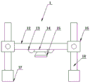
FIG. 2 is a schematic structural view of an upper surface optical inspection assembly in an auxiliary positioning tool for optical inspection of a machined part;
FIG. 3 is a schematic structural view of a lower surface optical detection assembly in an auxiliary positioning tool for optical inspection of a machined part;
fig. 4 is an enlarged view of a portion a in fig. 1.
Detailed Description
Referring to fig. 1 to 4, in the embodiment of the present invention, an auxiliary positioning tool for optical inspection of a machined part includes a detection positioning table 2, a positioning clamping assembly, a correcting swing-in assembly, an upper surface optical detection assembly 1, and a lower surface optical detection assembly 3, wherein the positioning clamping assembly is disposed on the upper surface of the detection positioning table, the upper surface optical detection assembly 1 is disposed above the detection positioning table 2, and the lower surface optical detection assembly 3 is disposed below the detection positioning table 2; the automatic correcting and swinging device is characterized in that at least one side of the positioning and clamping assembly is provided with the correcting and swinging assembly, and the correcting and swinging assembly can finely adjust and correct the position of a workpiece placed in the manipulator so as to enable the workpiece to be detected to be placed in a clamping cavity of the positioning and clamping assembly in a proper posture so as to clamp the workpiece;
the upper surface optical detection assembly 1 and the lower surface optical detection assembly 3 can be independently controlled to move up and down, so that the distance between the upper surface optical detection assembly 1 and the lower surface optical detection assembly 3 and the upper surface and the lower surface of the workpiece to be detected clamped in the positioning and clamping assembly can be adjusted, and the optical detection of the upper surface and the lower surface of the workpiece to be detected at a specific distance is guaranteed.
In the present embodiment, the corrective swing-in component includes at least two corrective swing-in claws 20, the corrective swing-in claws 20 are obliquely arranged on the outer side of the positioning and clamping component, and the corrective swing-in claws 20 can slightly oscillate in the direction toward the clamping cavity of the positioning and clamping component.
In a preferred embodiment, the upper end face of the correcting swing-in claw is higher than the upper end face of the positioning and clamping component.
Wherein, the location clamping unit includes fixed block 4, movable block 6 and slide bar 5, wherein, the last fixed surface who detects location platform 2 installs fixed block 4, the right side fixed mounting of fixed block 4 has limit baffle 8, and the right side of fixed block 4 has the doctor-bar 9 of preventing at limit baffle 8's front fixed surface, certainly, as other embodiment, limit baffle 8's front surface (also be the medial surface) also can set up the thimble, utilizes the top to push up tightly or press from both sides tightly to the work piece, the front fixed surface of fixed block 4 installs slide bar 5, the other end fixed mounting of slide bar 5 has movable block 6, the front surface mounting of movable block 6 has adjusting bolt 7.
In the invention, the correcting swing-in claw is arranged at the outer side of the limiting baffle 8, and the limiting baffles 8 at two sides are provided with the correcting swing-in claw.
The upper surface optical detection component 1 comprises a top plate 10, a first supporting rod 12, a second supporting rod 13, a correction pressing head seat 14, a correction pressing head 15, a lantern ring 16, a first base 17 and a main rod 18, a main rod 18 is fixedly arranged on the upper surface of the first base 17, a lantern ring 16 is sleeved outside the main rod 18 in a sliding manner, a first supporting rod 12 is fixedly arranged on the side surface of the lantern ring 16, a second supporting rod 13 is arranged between the two first supporting rods 12, a correcting and pressing head seat 14 is fixedly arranged between the side surfaces of the two second supporting rods 13, the lower surface of the correcting and pressing head seat 14 is fixedly provided with a correcting and pressing head 15, the top of the main rod 18 is provided with a top plate 10, the top plate is connected with the correcting and pressing head seat 14 through a linear lifting driving mechanism 19, so as to drive the correcting and pressing head seat 14 to move up and down, and the surface roughness optical detector is arranged at the inner side of the center of the correcting and pressing head seat.
Lower surface optical detection subassembly 3 is including detecting seat 39, spacing groove 31, mounting groove 32, drive piece 33, stopper 34, gag lever post 35, second base 36, lift cylinder 37 and lifter 38, a plurality of spacing grooves 31 have been seted up to the inside of detecting seat 32, the inside of gag lever post 31 slides from top to bottom and is provided with stopper 34, the lower fixed surface of stopper 34 installs gag lever post 35, the lower fixed surface of gag lever post 35 installs second base 36, the inside of second base 36 is provided with lifter 38, the lower fixed surface of lifter 38 installs lift cylinder 37, and the last fixed surface of lifter 38 installs drive piece 33, drive the piece with the bottom side fixed connection who detects the seat.
The correction pressing head 15 is of an elastic structure, and through holes corresponding to the sizes and the positions of the upper surface optical detection assembly and the lower surface optical detection assembly are formed in the positions, corresponding to the clamping cavities of the positioning and clamping assemblies, of the detection positioning table.
The correcting swing-in claw 20 is hinged to the outer side of the limit baffle 8, and an oscillating swing driver for driving the correcting swing-in claw 20 to swing is arranged at the hinged position. The oscillating swing driver can be driven by a motor matched with a gear or an electromagnetic driving mechanism, and the auxiliary positioning tool is used for detecting and positioning the roughness of the upper surface and the lower surface of a workpiece.
The correcting and swinging-in component can finely adjust and correct the position of a workpiece placed in a manipulator, so that the workpiece to be detected is placed in a clamping cavity of the positioning and clamping component in a proper posture to clamp the workpiece, automatic positioning and clamping are facilitated, automatic detection is achieved, and large-scale detection requirements are met; the upper surface optical detection assembly and the lower surface optical detection assembly can independently control the upper surface optical detection assembly and the lower surface optical detection assembly to move up and down, so that the distances between the upper surface optical detection assembly and the lower surface optical detection assembly and the upper surface and the lower surface of the workpiece to be detected after being clamped in the positioning and clamping assembly can be adjusted, the upper surface and the lower surface of the workpiece to be detected can be optically detected at a specific distance, and the work efficiency of part inspection and the accuracy of data are improved. The correcting swing-in claw can perform micro-amplitude oscillation in the direction facing the clamping cavity of the positioning and clamping assembly, so that a workpiece can be conveniently and automatically placed into the clamping cavity, the automatic position correction is realized, and the detection precision and the automation degree are improved.
The above description is only for the preferred embodiment of the present invention, but the scope of the present invention is not limited thereto, and any person skilled in the art should be considered to be within the technical scope of the present invention, and the technical solutions and the inventive concepts thereof according to the present invention are equivalent to or changed within the technical scope of the present invention.
Claims (5)
1. An auxiliary positioning tool for optical inspection of machined parts comprises a detection positioning table (2), a positioning clamping assembly, a correcting swing-in assembly, an upper surface optical detection assembly (1) and a lower surface optical detection assembly (3), wherein the positioning clamping assembly is arranged on the upper surface of the detection positioning table, the upper surface optical detection assembly (1) is arranged above the detection positioning table (2), and the lower surface optical detection assembly (3) is arranged below the detection positioning table (2); it is characterized in that the preparation method is characterized in that,
the correcting swing-in component is arranged on at least one side of the positioning and clamping component and can be used for finely adjusting and correcting the position of a workpiece placed in the manipulator, so that the workpiece to be detected is placed in a clamping cavity of the positioning and clamping component in a proper posture to clamp the workpiece;
the upper surface optical detection assembly (1) and the lower surface optical detection assembly (3) can be independently controlled to move up and down, so that the distances between the upper surface optical detection assembly (1) and the lower surface optical detection assembly (3) and the upper surface and the lower surface of the workpiece to be detected clamped in the positioning and clamping assembly can be adjusted, and the optical detection of the upper surface and the lower surface of the workpiece to be detected at a specific distance is further ensured;
the correcting swing-in component comprises at least two correcting swing-in claws (20), the correcting swing-in claws (20) are obliquely arranged on the outer side of the positioning and clamping component, and the correcting swing-in claws (20) can slightly oscillate in the direction towards the clamping cavity of the positioning and clamping component;
the upper end surface of the correcting swing-in claw is higher than the upper end surface of the positioning and clamping component;
the positioning and clamping assembly comprises a fixed block (4), a movable block (6) and a sliding rod (5), wherein the fixed surface of the upper surface of the detection and positioning table (2) is fixedly provided with the fixed block (4), the right side of the fixed block (4) is fixedly provided with a limit baffle (8), the right side of the fixed block (4) is fixedly provided with a scraping-proof blade (9) on the front surface of the limit baffle (8), the front surface of the fixed block (4) is fixedly provided with the sliding rod (5), the other end of the sliding rod (5) is fixedly provided with the movable block (6), and the front surface of the movable block (6) is provided with an adjusting bolt (7);
the upper surface optical detection assembly (1) comprises a top plate (10), a first branch rod (12), a second branch rod (13), a correction pressing head seat (14), a correction pressing head (15), a lantern ring (16), a first base (17) and a main rod (18), wherein the main rod (18) is fixedly installed on the upper surface of the first base (17), the lantern ring (16) is sleeved on the outer portion of the main rod (18) in a sliding mode, the first branch rod (12) is fixedly installed on the side surface of the lantern ring (16), the second branch rod (13) is arranged between the two first branch rods (12), the correction pressing head seat (14) is fixedly installed between the side surfaces of the two second branch rods (13), the correction pressing head seat (15) is fixedly installed on the lower surface of the correction pressing head seat (14), the top plate (10) is arranged on the top of the main rod (18), and the correction pressing head seat (14) is connected through a linear lifting driving mechanism (19), so as to drive the correcting and pressing head seat (14) to move up and down, and the surface roughness optical detector is arranged at the inner side of the center of the correcting and pressing head seat; the correction pressing head (15) is of an elastic structure, and the auxiliary positioning tool is used for detecting and positioning the roughness of the upper surface and the lower surface of the workpiece.
2. The auxiliary positioning tool for the optical inspection of the machined part as claimed in claim 1, wherein the correcting swing-in claw is arranged outside the limit baffle (8), and the limit baffles (8) on both sides are provided with the correcting swing-in claw.
3. The auxiliary positioning tool for the optical inspection of the machined part as claimed in claim 1, wherein the lower surface optical detection assembly (3) comprises a detection seat (39), a limiting groove (31), a mounting groove (32), a driving block (33), a limiting block (34), a limiting rod (35), a second base (36), a lifting cylinder (37) and a lifting rod (38), wherein a plurality of limiting grooves (31) are formed in the detection seat (39), the limiting block (34) is arranged in the limiting groove (31) in a vertical sliding manner, the limiting rod (35) is fixedly mounted on the lower surface of the limiting block (34), the second base (36) is fixedly mounted on the lower surface of the limiting rod (35), the lifting rod (38) is arranged in the second base (36), and the lifting cylinder (37) is fixedly mounted on the lower surface of the lifting rod (38), and a driving block (33) is fixedly arranged on the upper surface of the lifting rod (38), and the driving block is fixedly connected with the bottom side of the detection seat.
4. The auxiliary positioning tool for the optical inspection of the machined part as claimed in claim 1, wherein the position of the detection positioning table corresponding to the clamping cavity of the positioning and clamping assembly is provided with a through hole corresponding to the size and position of the upper surface optical detection assembly and the lower surface optical detection assembly.
5. The auxiliary positioning tool for the optical inspection of the machined part as claimed in claim 1, wherein the correcting swing-in claw (20) is hinged to the outer side of the limit baffle (8), and an oscillating swing driver for driving the correcting swing-in claw (20) to swing is arranged at the hinged position.
Priority Applications (1)
| Application Number | Priority Date | Filing Date | Title |
|---|---|---|---|
| CN201911361577.4A CN111055223B (en) | 2019-12-26 | 2019-12-26 | Auxiliary positioning tool for optical inspection of machined parts |
Applications Claiming Priority (1)
| Application Number | Priority Date | Filing Date | Title |
|---|---|---|---|
| CN201911361577.4A CN111055223B (en) | 2019-12-26 | 2019-12-26 | Auxiliary positioning tool for optical inspection of machined parts |
Publications (2)
| Publication Number | Publication Date |
|---|---|
| CN111055223A CN111055223A (en) | 2020-04-24 |
| CN111055223B true CN111055223B (en) | 2021-10-01 |
Family
ID=70303719
Family Applications (1)
| Application Number | Title | Priority Date | Filing Date |
|---|---|---|---|
| CN201911361577.4A Active CN111055223B (en) | 2019-12-26 | 2019-12-26 | Auxiliary positioning tool for optical inspection of machined parts |
Country Status (1)
| Country | Link |
|---|---|
| CN (1) | CN111055223B (en) |
Families Citing this family (1)
| Publication number | Priority date | Publication date | Assignee | Title |
|---|---|---|---|---|
| CN113862443B (en) * | 2021-09-30 | 2024-03-22 | 江苏丰东热技术有限公司 | Auxiliary positioning device for thermal state workpiece |
Citations (5)
| Publication number | Priority date | Publication date | Assignee | Title |
|---|---|---|---|---|
| JPH04166752A (en) * | 1990-10-29 | 1992-06-12 | Nippon Steel Corp | Apparatus for inspecting flaw of container |
| CN1621818A (en) * | 2003-11-28 | 2005-06-01 | 三星康宁精密琉璃株式会社 | Cutting surface testing apparatus for glass substrate |
| CN204053845U (en) * | 2014-06-27 | 2014-12-31 | 深圳市索恩达电子有限公司 | Pcb board automatic clamping device on a kind of tin cream detector |
| CN107532877A (en) * | 2015-05-25 | 2018-01-02 | 日本电气硝子株式会社 | Surface roughness evaluation method, surface roughness evaluating apparatus and glass substrate |
| CN209507219U (en) * | 2019-01-29 | 2019-10-18 | 郑州轻工业学院 | A kind of electroplating assembly line anti-deviation device |
-
2019
- 2019-12-26 CN CN201911361577.4A patent/CN111055223B/en active Active
Patent Citations (5)
| Publication number | Priority date | Publication date | Assignee | Title |
|---|---|---|---|---|
| JPH04166752A (en) * | 1990-10-29 | 1992-06-12 | Nippon Steel Corp | Apparatus for inspecting flaw of container |
| CN1621818A (en) * | 2003-11-28 | 2005-06-01 | 三星康宁精密琉璃株式会社 | Cutting surface testing apparatus for glass substrate |
| CN204053845U (en) * | 2014-06-27 | 2014-12-31 | 深圳市索恩达电子有限公司 | Pcb board automatic clamping device on a kind of tin cream detector |
| CN107532877A (en) * | 2015-05-25 | 2018-01-02 | 日本电气硝子株式会社 | Surface roughness evaluation method, surface roughness evaluating apparatus and glass substrate |
| CN209507219U (en) * | 2019-01-29 | 2019-10-18 | 郑州轻工业学院 | A kind of electroplating assembly line anti-deviation device |
Also Published As
| Publication number | Publication date |
|---|---|
| CN111055223A (en) | 2020-04-24 |
Similar Documents
| Publication | Publication Date | Title |
|---|---|---|
| US11331729B2 (en) | Wheel hub special drilling device | |
| CN111055223B (en) | Auxiliary positioning tool for optical inspection of machined parts | |
| CN209792912U (en) | computer cover plate shell laser etching jig | |
| CN105834636A (en) | Quick assembling follow fixture device for overcoming surface microdefects of large-diameter curved surface optical element | |
| US9694461B2 (en) | Transfer center for machining at least one workpiece | |
| CN211601876U (en) | Micro-aperture measuring device | |
| CN110883582A (en) | Axle housing milling surface drilling clamp | |
| CN110936142A (en) | Auxiliary structure for assembling automobile seat slide rail screw rod and gear box | |
| CN211939782U (en) | Auxiliary structure for assembling automobile seat slide rail screw rod and gear box | |
| CN213646745U (en) | Clamp for processing air conditioner panel | |
| CN108724063B (en) | Tire taper point matching system | |
| CN104308208B (en) | A kind of chuck linking fixture | |
| CN219053653U (en) | Automatic middle-separating tool for large castings | |
| CN211332328U (en) | Alignment frock clamp of part machining | |
| CN210702668U (en) | Air chamber support machining device | |
| CN112276679B (en) | Automobile glass lifter guide rail selection type error proofing device | |
| CN221538565U (en) | Flexible frock of car body panel laser cutting | |
| CN217452189U (en) | Drilling equipment is used in machine part processing | |
| CN209831051U (en) | Intelligent machining workstation | |
| CN221538508U (en) | Visual laser coding machine | |
| CN220428063U (en) | Workpiece clamping jig capable of being placed obliquely | |
| CN219649830U (en) | Positioning fixture | |
| CN221675845U (en) | Efficient and convenient numerical control lathe shaft machining centering pin support | |
| CN212705625U (en) | Pneumatic positioning clamp for safety copying machine | |
| CN218238624U (en) | Needle tubing detects correction tool |
Legal Events
| Date | Code | Title | Description |
|---|---|---|---|
| PB01 | Publication | ||
| PB01 | Publication | ||
| SE01 | Entry into force of request for substantive examination | ||
| SE01 | Entry into force of request for substantive examination | ||
| GR01 | Patent grant | ||
| GR01 | Patent grant |