CN1110352C - Modular filtration systems and methods - Google Patents
Modular filtration systems and methods Download PDFInfo
- Publication number
- CN1110352C CN1110352C CN98804189A CN98804189A CN1110352C CN 1110352 C CN1110352 C CN 1110352C CN 98804189 A CN98804189 A CN 98804189A CN 98804189 A CN98804189 A CN 98804189A CN 1110352 C CN1110352 C CN 1110352C
- Authority
- CN
- China
- Prior art keywords
- fluid flowing
- flowing passage
- fluid
- module
- feeding
- Prior art date
- Legal status (The legal status is an assumption and is not a legal conclusion. Google has not performed a legal analysis and makes no representation as to the accuracy of the status listed.)
- Expired - Fee Related
Links
- 238000001914 filtration Methods 0.000 title claims abstract description 17
- 238000000034 method Methods 0.000 title description 4
- 239000012530 fluid Substances 0.000 claims abstract description 83
- 238000004519 manufacturing process Methods 0.000 claims abstract description 37
- 238000001223 reverse osmosis Methods 0.000 claims description 3
- 238000006243 chemical reaction Methods 0.000 claims description 2
- 239000012528 membrane Substances 0.000 claims 1
- 239000002699 waste material Substances 0.000 abstract description 5
- 230000037431 insertion Effects 0.000 abstract 1
- 238000003780 insertion Methods 0.000 abstract 1
- 230000013011 mating Effects 0.000 abstract 1
- XLYOFNOQVPJJNP-UHFFFAOYSA-N water Substances O XLYOFNOQVPJJNP-UHFFFAOYSA-N 0.000 description 11
- 239000002351 wastewater Substances 0.000 description 6
- 239000013505 freshwater Substances 0.000 description 5
- 238000010586 diagram Methods 0.000 description 3
- 239000012266 salt solution Substances 0.000 description 3
- 230000007704 transition Effects 0.000 description 3
- 230000032258 transport Effects 0.000 description 3
- 230000008901 benefit Effects 0.000 description 2
- 230000008859 change Effects 0.000 description 2
- 238000013461 design Methods 0.000 description 2
- 238000005516 engineering process Methods 0.000 description 2
- 238000001764 infiltration Methods 0.000 description 2
- 230000004048 modification Effects 0.000 description 2
- 238000012986 modification Methods 0.000 description 2
- 230000003466 anti-cipated effect Effects 0.000 description 1
- 238000004891 communication Methods 0.000 description 1
- 238000011109 contamination Methods 0.000 description 1
- 238000010612 desalination reaction Methods 0.000 description 1
- 238000004821 distillation Methods 0.000 description 1
- 230000035622 drinking Effects 0.000 description 1
- 230000000694 effects Effects 0.000 description 1
- 230000003203 everyday effect Effects 0.000 description 1
- 239000003337 fertilizer Substances 0.000 description 1
- 230000005484 gravity Effects 0.000 description 1
- 239000007788 liquid Substances 0.000 description 1
- 239000000203 mixture Substances 0.000 description 1
- 235000015205 orange juice Nutrition 0.000 description 1
- 230000035699 permeability Effects 0.000 description 1
- 238000011045 prefiltration Methods 0.000 description 1
- 238000012797 qualification Methods 0.000 description 1
- 150000003839 salts Chemical class 0.000 description 1
- 230000011218 segmentation Effects 0.000 description 1
- 238000000926 separation method Methods 0.000 description 1
- 239000007787 solid Substances 0.000 description 1
- 238000000108 ultra-filtration Methods 0.000 description 1
Images


Classifications
-
- B—PERFORMING OPERATIONS; TRANSPORTING
- B01—PHYSICAL OR CHEMICAL PROCESSES OR APPARATUS IN GENERAL
- B01D—SEPARATION
- B01D63/00—Apparatus in general for separation processes using semi-permeable membranes
-
- F—MECHANICAL ENGINEERING; LIGHTING; HEATING; WEAPONS; BLASTING
- F16—ENGINEERING ELEMENTS AND UNITS; GENERAL MEASURES FOR PRODUCING AND MAINTAINING EFFECTIVE FUNCTIONING OF MACHINES OR INSTALLATIONS; THERMAL INSULATION IN GENERAL
- F16L—PIPES; JOINTS OR FITTINGS FOR PIPES; SUPPORTS FOR PIPES, CABLES OR PROTECTIVE TUBING; MEANS FOR THERMAL INSULATION IN GENERAL
- F16L9/00—Rigid pipes
- F16L9/006—Rigid pipes specially profiled
-
- B—PERFORMING OPERATIONS; TRANSPORTING
- B01—PHYSICAL OR CHEMICAL PROCESSES OR APPARATUS IN GENERAL
- B01D—SEPARATION
- B01D61/00—Processes of separation using semi-permeable membranes, e.g. dialysis, osmosis or ultrafiltration; Apparatus, accessories or auxiliary operations specially adapted therefor
- B01D61/02—Reverse osmosis; Hyperfiltration ; Nanofiltration
- B01D61/025—Reverse osmosis; Hyperfiltration
- B01D61/026—Reverse osmosis; Hyperfiltration comprising multiple reverse osmosis steps
-
- B—PERFORMING OPERATIONS; TRANSPORTING
- B01—PHYSICAL OR CHEMICAL PROCESSES OR APPARATUS IN GENERAL
- B01D—SEPARATION
- B01D61/00—Processes of separation using semi-permeable membranes, e.g. dialysis, osmosis or ultrafiltration; Apparatus, accessories or auxiliary operations specially adapted therefor
- B01D61/02—Reverse osmosis; Hyperfiltration ; Nanofiltration
- B01D61/06—Energy recovery
-
- B—PERFORMING OPERATIONS; TRANSPORTING
- B01—PHYSICAL OR CHEMICAL PROCESSES OR APPARATUS IN GENERAL
- B01D—SEPARATION
- B01D61/00—Processes of separation using semi-permeable membranes, e.g. dialysis, osmosis or ultrafiltration; Apparatus, accessories or auxiliary operations specially adapted therefor
- B01D61/02—Reverse osmosis; Hyperfiltration ; Nanofiltration
- B01D61/08—Apparatus therefor
-
- B—PERFORMING OPERATIONS; TRANSPORTING
- B01—PHYSICAL OR CHEMICAL PROCESSES OR APPARATUS IN GENERAL
- B01D—SEPARATION
- B01D61/00—Processes of separation using semi-permeable membranes, e.g. dialysis, osmosis or ultrafiltration; Apparatus, accessories or auxiliary operations specially adapted therefor
- B01D61/02—Reverse osmosis; Hyperfiltration ; Nanofiltration
- B01D61/10—Accessories; Auxiliary operations
-
- B—PERFORMING OPERATIONS; TRANSPORTING
- B01—PHYSICAL OR CHEMICAL PROCESSES OR APPARATUS IN GENERAL
- B01D—SEPARATION
- B01D63/00—Apparatus in general for separation processes using semi-permeable membranes
- B01D63/10—Spiral-wound membrane modules
- B01D63/12—Spiral-wound membrane modules comprising multiple spiral-wound assemblies
-
- B—PERFORMING OPERATIONS; TRANSPORTING
- B01—PHYSICAL OR CHEMICAL PROCESSES OR APPARATUS IN GENERAL
- B01D—SEPARATION
- B01D63/00—Apparatus in general for separation processes using semi-permeable membranes
- B01D63/14—Pleat-type membrane modules
-
- B—PERFORMING OPERATIONS; TRANSPORTING
- B01—PHYSICAL OR CHEMICAL PROCESSES OR APPARATUS IN GENERAL
- B01D—SEPARATION
- B01D65/00—Accessories or auxiliary operations, in general, for separation processes or apparatus using semi-permeable membranes
- B01D65/02—Membrane cleaning or sterilisation ; Membrane regeneration
-
- B—PERFORMING OPERATIONS; TRANSPORTING
- B01—PHYSICAL OR CHEMICAL PROCESSES OR APPARATUS IN GENERAL
- B01D—SEPARATION
- B01D65/00—Accessories or auxiliary operations, in general, for separation processes or apparatus using semi-permeable membranes
- B01D65/08—Prevention of membrane fouling or of concentration polarisation
-
- B—PERFORMING OPERATIONS; TRANSPORTING
- B01—PHYSICAL OR CHEMICAL PROCESSES OR APPARATUS IN GENERAL
- B01D—SEPARATION
- B01D2321/00—Details relating to membrane cleaning, regeneration, sterilization or to the prevention of fouling
- B01D2321/02—Forward flushing
-
- C—CHEMISTRY; METALLURGY
- C02—TREATMENT OF WATER, WASTE WATER, SEWAGE, OR SLUDGE
- C02F—TREATMENT OF WATER, WASTE WATER, SEWAGE, OR SLUDGE
- C02F1/00—Treatment of water, waste water, or sewage
- C02F1/44—Treatment of water, waste water, or sewage by dialysis, osmosis or reverse osmosis
- C02F1/441—Treatment of water, waste water, or sewage by dialysis, osmosis or reverse osmosis by reverse osmosis
-
- C—CHEMISTRY; METALLURGY
- C02—TREATMENT OF WATER, WASTE WATER, SEWAGE, OR SLUDGE
- C02F—TREATMENT OF WATER, WASTE WATER, SEWAGE, OR SLUDGE
- C02F1/00—Treatment of water, waste water, or sewage
- C02F1/72—Treatment of water, waste water, or sewage by oxidation
- C02F1/78—Treatment of water, waste water, or sewage by oxidation with ozone
Abstract
A filtration system includes production modules (305) which are mechanically coupled in series, and which contain filters that are fluidly coupled in parallel. Among the many different possibilities contemplated, each production module may advantageously contain not only a filter (3.4), but also flowpaths for feed fluid (334a), waste fluid (334b), and product fluid (334c) so that a series of coupled modules can be installed, accessed, and removed as single unit. It is further contemplated that coupled modules may be deployed in space efficient manner, such as by insertion into a deep or shall well, a tower, along the ground, into the side of a hill or mountain, or even under a road or parking lot. It is still further contemplated that adjacent production modules may be designed to mate with one another using a slip fit joint, and that the production modules may be maintained in mating relationship through connections to supporting cables or rods.
Description
Technical field
The present invention relates to a kind of modular filtration system.
Background technology
Now, worldwide have demand to bodies for purifying fluids, in these bodies for purifying fluids commercial most important a kind of be exactly to produce fresh water by salt solution or brackish water.Except that distillation technique, generally also can satisfy this demand by filtration.A variety of filter methods are arranged now, comprise counter-infiltration, ultrafiltration and high filter method, all these technology all are considered to fall in the scope of generic term " filtration " in this manual.
Most of filter comprises that all one holds the flow channel of the container of filter and three and extraneous UNICOM.Article one, passage transports a feeding fluid, and another flow channel transports the fluid (being product) that is filtered, and the 3rd passage transports waste material, the waste material discarded fluid that is otherwise known as sometimes.If adopt reverse osmosis unit to purify brackish water, the feeding fluid is exactly a brackish water so, and the fluid of filtration is exactly desalted water (fresh water), and discarded fluid is exactly a salt solution.
Filter factory and generally comprise many physical separation filter elements that are arranged on the ground or are provided with near ground.The fluid of feeding fluid, filtration and discarded fluid respectively by three independently pipeline be transported, and each filter element all is connected with every pipeline fluid with sebific duct or other pipeline.In such embodiments, whole system is by modularization, and various filter element comprises described module again simultaneously.Different modules more or less mechanically are arranged in parallel, and various film spare is arranged in parallel by fluid.This set has lot of advantages, and not only individual module can disconnect so that safeguard from system, and the other parts of system are also unaffected.
Except that around per five compositions, one cover of its various reverse osmosis units (being called as permeability apparatus) is arranged at a public standpipe, the United States Patent (USP) 4,125,463 that licenses to Chenoweth has also adopted type same as described above.This structure allows a plurality of unit to be assemblied in easily in the sleeve pipe.But this patent does not disclose the enlightenment and the suggestion of any type about super module, that is does not have to disclose and can comprise five R0 unit of many covers and the super module that can connect and be provided with.
Still the suggestion of other document is provided with a housing that is used to hold filter element under deep water.And, can consider a plurality of modules more or less physics be arranged in parallel, and can consider that filter is arranged in parallel by fluid.
Yet the assembly of known setting is not have its limitation.The location of parallel component needs sizable space, in the embodiment of a commerce, in the time of on being arranged at ground, often needs in bigger " footprint ".Utilize the Chenoweth formula design of deep-well can utilize the space preferably, but owing to need a large amount of interconnection, therefore should design and impracticable.
Summary of the invention
The invention provides a kind of modular filtration system, it comprises: a feeding fluid flowing passage, a discarded fluid flowing passage and a finished product flow channel; A plurality of production modules, each module all comprise a spiral curved around filter, described filter is separated into three fluid of second fluid and in the finished product fluid flowing passage in discarded fluid flowing passage with the first fluid in the feeding fluid flowing passage; Described production module is arranged in the shell, in this shell, adjacent production modules mechanically be cascaded and discarded relatively fluid flowing passage and finished product fluid flowing passage one of at least in parallel; Described feeding fluid flowing passage, discarded fluid passage and finished product fluid flowing passage are parallel to each other on the whole length of each production module substantially; Walk around one of them described production module with a certain amount of feeding fluid.
This a certain amount of feeding fluid is to walk around between the outer wall of production module and a casing.In these a plurality of production modules at least one is in the blow-by of shell place
In the various possibilities that these reckon with, each production module all can advantageously comprise a filter and all three passages, thereby the module of series connection can be mounted, adjust and dismantle as a unit.In addition, it is also anticipated that: interconnected module can the conserve space mode be configured, and for example by being inserted into deep-well, control tower, inserts the side of massif along ground, perhaps even insert under highway or the parking lot.Can also further reckon with: adjacent production modules can be designed to utilize one to be slidingly matched joint and to cooperatively interact, and the production module can be by remaining in mated condition with being connected of support cable or cramp bar.
In conjunction with the accompanying drawings,, will know various objectives of the present invention, feature, aspect and advantage, wherein similar parts like the Reference numeral representation class with reference to the explanation of most preferred embodiment.
Description of drawings
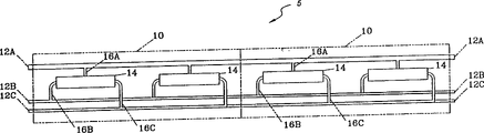
Fig. 1 is the exploded sketch of the filtration system according to the present invention;
Fig. 2 is the schematic diagram of the most preferred embodiment that is arranged at underground (well-based) filtration system according to the present invention;
Fig. 3 is the three-dimensional partial sectional view of a house steward of the production module according to the present invention;
Fig. 4 is the schematic diagram of the most preferred embodiment that is arranged at ground filtration system according to the present invention.
The specific embodiment
In Fig. 1, filtration system 5 generally comprises a plurality of end to end production moulds and determines 10.Each module 10 all comprises three pipelines: feeding pipeline 12A, waste material pipeline 12B and a finished product pipeline 12C.Different pipelines is respectively by branch road 16A, 16B and 16C and filter 14 fluid communication.In a word, the feeding fluid flows to filter 14 by pipeline 12A and 16A, and filter 14 is separated into waste streams and product stream.Waste water enters pipeline 12B by pipeline 16B, and finished product enters pipeline 12C by pipeline 16C.Pipeline 12A, 12B and 12C are connected on another module from a module, thereby make various fluids all flow through the module of all series connection.
Can see that from Fig. 2 system 105 comprises module and the connection that other is used for most preferred embodiment.In the present embodiment, feeding water 120A, for example salt solution or brackish water are upwards extracted out by pump 133, enter a underground counter-infiltration production chamber by a feeding pipeline 131.Then, the moving passage 134A of feeding water 120A longshore current flows to the filter 150 in the module 110 downwards, is separated into fresh water finished product 120C and waste water 120B in module 110.Fresh water finished product 120C upwards flows and flow to gatherer 140 under the help of pump 135 along passage 134C.Waste water 120B upwards flows along waste water tunnel 134B, and discharges from system 5 by pipeline 150.Like this, various module 110 machineries are cascaded, and fluid filter 150 relative fluid flowing passage 134A, 134B and 134C are connected in parallel.
Fig. 2 shows a derrick (headwork) 111 and a transition module (transitionmodule) 160, the transition between pump or the production module and the face of land of this transition module 160.Still can reckon with: adjacent production modules 100 can be designed to cooperatively interact by the joint (not shown) that is slidingly matched, and the production module also can be by being in mated condition with being connected of support cable or cramp bar.
Fig. 3 shows a house steward 210, and this house steward can be arranged on the end of production module, to connect with adjacent modules and different flow channel.Wherein, house steward 210 has formed several conduit 216, one feeding fluids and had flowed to (seeing arrow 206) internal flow space 200 from feeding fluid supply space 134A (see figure 2) by this conduit before flowing to the filter (not shown).Different conduits 216 is formed in the rib 217, and rib 217 also is used to support the pipeline 260 of a qualification finished product passage.We can appreciate that immediately the waste water that flows through the filter in the module 210 is mobile along the direction of arrow 208, therefore also just flow along passage 134C (see figure 2).
In Fig. 4, system 305 briefly shows a ground embodiment, and in this embodiment, feeding water 320 is upwards extracted out by pump 333, enters prefilter 335 and merit conversion pump (work exchange pump) 336 by a feeding pipeline 331.Feeding water 320A enters two production units 310 then by feeding pipeline 331B through feeding fluid passage 334A.In case enter in the production unit 310, some feeding fluid 320A will pass through filter 314, and to form finished product 320C, finished product 320C is collected in finished product passage 334C.Next, finished product 320C flows to gatherer 340 under the effect of gravity.The fluid by filter 314 does not just become waste water 320B, and flows along passage 334C, and discharges from system.Like this, identical with the embodiment of Fig. 2, in the present embodiment, a plurality of parts of a passage (fluid passage 334A is given in fingering here) are arranged between module 310 and the shell 390.Certainly, also can expect other embodiment, a plurality of parts of wherein one or more different flow channels are included in the module 310.
Can expect: the embodiment among Fig. 4 preferably includes 2 to 50 or more production unit 310, and the length of each production unit is preferably about 10 feet to 20 feet.The diameter of shell is preferably about 30 inches, but also can have bigger or less diameter, and in fact, also can have the cross section of non-circle.Based on existing filter, this system is expected to produce every day about 2,000,000 gallons fresh water or other finished product fluid.
Other details that can be applicable to the present invention's optimum decision system discloses in WO98/09718, and integral body is quoted in this manual.These details relate to the module of pump, the suitable dimension of adequate types, suitable system attitude and setting, suitable filter or the like.Especially can imagine obtain be the embodiment that those operation filters required pressure are provided by pump or liquid column (column ofliquid) substantially.For this reason, positive-dispacement pump is proper, in the time of specifically in such pump is assemblied in the work crosspoint.Feeding fluid tower also is suitable, specifically tower be at least 200 feet dark, be preferably at least 500 feet dark, at least 1000 feet are dark better, but be preferably at least 1500 feet dark.
Certainly, there are many above-mentioned total interior modifications of inventive concept that fall into.For example, in Fig. 1, show all three fluid circuit 12A, 12B and 12C integral body and be included in the production module 10.Yet, in alternate embodiments, any one or any two or all three fluid circuits can be arranged at outside the production module 10.Because feeding fluid 120A flows in the passage 134A of module 110 outsides, promptly between module 110 and casing, flow, so Fig. 2 is a kind of suitable situation.In other is revised, can be arranged to the structure and the configuration of a great difference according to filtration system of the present invention.For example, system can be constructed to a single long tube, also can be configured to the short tube of " segmentation ", perhaps even be curve or circle.And system also can be set on the ground, subsurface, and part part on the ground vertically is provided with or is horizontally disposed with at subsurface, and with the arbitrarily angled setting between upright position and the horizontal level.
Be appreciated that feeding fluid, discarded fluid and finished product fluid all can change with the change of system, therefore should consider its setting from wide significance.For example, the feeding fluid may only be polluted by a spot of ordinary salt, also may be by organic and inorganic, solubilized or suspended solid severe contamination.Similarly, the discarded fluid in the desalination system may not exclusively be useless, and can be transported to the secondary filter system with high pressure.In addition, for drinking the filtration of fluid, orange juice for example, discarded fluid may have very high commercial value, for example as animal feed or fertilizer.Along identical pipeline, the finished product fluid needn't be pure especially.Pure is relative, and some system can be used to produce water or other fluid that is considered to not drinkable usually.
Like this, modular filtration system is disclosed, and in this system, module is connected mutually, and the parallel connection of filter fluid.Although specific embodiment and application have been made explanation and diagram, it will be apparent to those skilled in the art: without departing from the inventive concept of the premise, can make more modification to it.Therefore, the present invention is not limited only to the scope of appended claims.
Claims (12)
1, a kind of modular filtration system, it comprises:
One feeding fluid flowing passage, a discarded fluid flowing passage and a finished product flow channel;
A plurality of production modules, each module all comprise a spiral curved around filter, described filter is separated into three fluid of second fluid and in the finished product fluid flowing passage in discarded fluid flowing passage with the first fluid in the feeding fluid flowing passage;
Described production module is arranged in the shell, in this shell, adjacent production modules mechanically be cascaded and discarded relatively fluid flowing passage and finished product fluid flowing passage one of at least in parallel;
Described feeding fluid flowing passage, discarded fluid passage and finished product fluid flowing passage are parallel to each other on the whole length of each production module substantially; With
A certain amount of feeding fluid is walked around one of them described production module.
2, system according to claim 1 is characterized in that: each production module all comprises the part of feeding fluid flowing passage, discarded fluid flowing passage and finished product flow channel.
3, system according to claim 1 is characterized in that: described each production module all comprises in feeding fluid flowing passage, discarded fluid flowing passage and the finished product flow channel part of at least two.
4, system according to claim 1 is characterized in that: described each production module all comprises feeding fluid flowing passage, a discarded fluid flowing passage and finished product flow channel part one of at least.
5, system according to claim 1 is characterized in that: described module is arranged on the ground level at least in part.
6, system according to claim 1 is characterized in that: described module is arranged under the ground level at least in part.
7, system according to claim 1 is characterized in that: described filter is the reverse osmosis membrane structure.
8, according to the described system of one of claim 1 to 7, it is characterized in that, also comprise a pump to the pressurization of feeding fluid flowing passage.
9, according to the described system of one of claim 1 to 7, it is characterized in that, also comprise a merit conversion equipment to the pressurization of feeding fluid flowing passage.
10, according to the described system of one of claim 1 to 7, it is characterized in that, also comprise a fluid tower to the pressurization of feeding fluid flowing passage.
According to the described system of one of claim 1 to 7, it is characterized in that 11, this a certain amount of feeding fluid is to walk around between the outer wall of production module and a casing.
According to the described system of one of claim 1 to 7, it is characterized in that 12, at least one in these a plurality of production modules is in the blow-by of shell place.
Applications Claiming Priority (2)
| Application Number | Priority Date | Filing Date | Title |
|---|---|---|---|
| US4300197P | 1997-04-14 | 1997-04-14 | |
| US60/043,001 | 1997-04-14 |
Publications (2)
| Publication Number | Publication Date |
|---|---|
| CN1252738A CN1252738A (en) | 2000-05-10 |
| CN1110352C true CN1110352C (en) | 2003-06-04 |
Family
ID=21924920
Family Applications (1)
| Application Number | Title | Priority Date | Filing Date |
|---|---|---|---|
| CN98804189A Expired - Fee Related CN1110352C (en) | 1997-04-14 | 1998-04-13 | Modular filtration systems and methods |
Country Status (17)
| Country | Link |
|---|---|
| US (1) | US6521127B1 (en) |
| EP (1) | EP0983115B1 (en) |
| JP (1) | JP3669512B2 (en) |
| KR (1) | KR100417444B1 (en) |
| CN (1) | CN1110352C (en) |
| AT (1) | ATE249271T1 (en) |
| AU (1) | AU723518B2 (en) |
| CA (1) | CA2282403C (en) |
| DE (1) | DE69818038T2 (en) |
| ES (1) | ES2205479T3 (en) |
| HK (1) | HK1024652A1 (en) |
| ID (1) | ID23391A (en) |
| IL (1) | IL131491A (en) |
| MX (1) | MX215049B (en) |
| RU (1) | RU2190460C2 (en) |
| UA (1) | UA58544C2 (en) |
| WO (1) | WO1998046338A1 (en) |
Families Citing this family (22)
| Publication number | Priority date | Publication date | Assignee | Title |
|---|---|---|---|---|
| ATE241424T1 (en) * | 2000-12-22 | 2003-06-15 | Gruenbeck Josef Wasseraufb | DEVICE FOR PREPARING A LIQUID |
| DE10105181C1 (en) * | 2001-02-06 | 2002-07-11 | Aerodyn Eng Gmbh | Wind-powered energy plant for water desalination has mechanical energy provided by rotor used for driving pressure pump for reverse osmosis system |
| US7063789B2 (en) * | 2003-08-13 | 2006-06-20 | Koch Membrane Systems, Inc. | Filtration element and method of constructing a filtration assembly |
| US20050230312A1 (en) * | 2004-03-10 | 2005-10-20 | Dennis Chancellor | Configurations and methods for reduction of microbial growth in reverse osmosis devices |
| US7141171B2 (en) * | 2004-05-21 | 2006-11-28 | Wisconsin Alumni Research Foundation | Membrane cascade-based separation |
| US7338601B2 (en) * | 2004-12-10 | 2008-03-04 | Uop Llc | Membrane separation assemblies |
| EP1743689A1 (en) * | 2005-07-13 | 2007-01-17 | KRONES Aktiengesellschaft | Crossflow filtration apparatus and process |
| EP1788378A1 (en) * | 2005-11-22 | 2007-05-23 | BP Chemicals Limited | Method & apparatus for spectroscopic analysis |
| US20070181484A1 (en) * | 2006-02-07 | 2007-08-09 | Ge Osmonics, Inc. | Modular reverse osmosis water treatment system |
| US7758754B2 (en) * | 2007-01-09 | 2010-07-20 | Membrane Technology And Research, Inc | Pervaporation process and assembly |
| RU2446110C2 (en) * | 2008-10-27 | 2012-03-27 | Владимир Фёдорович Фомин | Hyperfiltration desalting plant |
| WO2011090399A1 (en) * | 2010-01-20 | 2011-07-28 | Fomin Vladimir Fjodorovich | Reverse osmosis water distilling module (variant embodiments) |
| US20110290728A1 (en) * | 2010-05-25 | 2011-12-01 | General Electric Company | SWRO Pressure Vessel and Process That Increases Production and Product Quality and Avoids Scaling Problems |
| CN201777948U (en) * | 2010-09-02 | 2011-03-30 | 林莹陈 | Water purifier waterway integrated block |
| AU2017330537A1 (en) | 2016-09-20 | 2019-04-11 | Aqua Membranes Llc | Permeate flow patterns |
| WO2018094287A1 (en) | 2016-11-19 | 2018-05-24 | Aqua Membranes Llc | Interfernce patterns for spiral-wound elements |
| EP3609607A4 (en) | 2017-04-12 | 2021-01-27 | Aqua Membranes, Inc. | Graded spacers for filtration wound elements |
| US11745143B2 (en) | 2017-04-20 | 2023-09-05 | Aqua Membranes, Inc. | Mixing-promoting spacer patterns for spiral-wound elements |
| US11083997B2 (en) | 2017-04-20 | 2021-08-10 | Aqua Membranes Inc. | Non-nesting, non-deforming patterns for spiral-wound elements |
| RU178724U1 (en) * | 2017-07-03 | 2018-04-18 | Владимир Иванович Вяликов | Portable reverse osmosis filter |
| CN111344053A (en) | 2017-10-13 | 2020-06-26 | 阿夸曼布拉尼斯公司 | Bridge support for spiral wound elements and reduced feed spacer |
| WO2021207256A1 (en) | 2020-04-07 | 2021-10-14 | Aqua Membranes Inc. | Independent spacers and methods |
Citations (3)
| Publication number | Priority date | Publication date | Assignee | Title |
|---|---|---|---|---|
| US4083780A (en) * | 1976-07-29 | 1978-04-11 | Envirogenics Systems Company | Fluid purification system |
| US4125463A (en) * | 1977-10-27 | 1978-11-14 | Chenoweth James W | Reverse osmosis desalination apparatus and method |
| US5366635A (en) * | 1992-11-27 | 1994-11-22 | Global Water Technologies, Inc. | Desalinization system and process |
Family Cites Families (11)
| Publication number | Priority date | Publication date | Assignee | Title |
|---|---|---|---|---|
| US4198293A (en) * | 1975-03-22 | 1980-04-15 | Hitachi, Ltd. | Tubular membrane separation process and apparatus therefor |
| JPS5527055A (en) * | 1978-08-17 | 1980-02-26 | Hitachi Plant Eng & Constr Co Ltd | Tube type membrane separator |
| US4702842A (en) * | 1987-01-16 | 1987-10-27 | Donald Lapierre | Apparatus for reverse osmosis using fluid recirculation |
| DD287200A5 (en) * | 1989-08-28 | 1991-02-21 | Veb Chemieanlagenbaukombinat Leipzig-Grimma,Stammbetrieb,De | Membrane separation unit |
| DE3936798C1 (en) * | 1989-11-04 | 1991-01-24 | Dortmunder Actien-Brauerei Ag, 4600 Dortmund, De | |
| US4988445A (en) * | 1990-02-22 | 1991-01-29 | Koch Membrane Systems, Inc. | Spiral wound filtration system and method of utilizing same |
| FR2721227B1 (en) * | 1994-06-17 | 1996-08-14 | Kodak Pathe | Method and device for the separation of dissolved substances in the rinsing water used downstream of a photographic film treatment bath. |
| US5470469A (en) * | 1994-09-16 | 1995-11-28 | E. I. Du Pont De Nemours And Company | Hollow fiber cartridge |
| US5914041A (en) * | 1996-09-03 | 1999-06-22 | Nate International | Channel based reverse osmosis |
| WO1998009718A1 (en) * | 1996-09-03 | 1998-03-12 | Nate International | Modular filtration system |
| US6004464A (en) * | 1998-07-14 | 1999-12-21 | Desalination Systems, Inc. | Spent brine reclamation |
-
1998
- 1998-04-13 IL IL13149198A patent/IL131491A/en not_active IP Right Cessation
- 1998-04-13 US US09/367,517 patent/US6521127B1/en not_active Expired - Fee Related
- 1998-04-13 WO PCT/US1998/007383 patent/WO1998046338A1/en active IP Right Grant
- 1998-04-13 KR KR19997009448A patent/KR100417444B1/en not_active IP Right Cessation
- 1998-04-13 AU AU71130/98A patent/AU723518B2/en not_active Ceased
- 1998-04-13 ID IDW991205A patent/ID23391A/en unknown
- 1998-04-13 CN CN98804189A patent/CN1110352C/en not_active Expired - Fee Related
- 1998-04-13 JP JP54415998A patent/JP3669512B2/en not_active Expired - Fee Related
- 1998-04-13 DE DE69818038T patent/DE69818038T2/en not_active Expired - Fee Related
- 1998-04-13 RU RU99123614/12A patent/RU2190460C2/en not_active IP Right Cessation
- 1998-04-13 ES ES98918153T patent/ES2205479T3/en not_active Expired - Lifetime
- 1998-04-13 EP EP98918153A patent/EP0983115B1/en not_active Expired - Lifetime
- 1998-04-13 AT AT98918153T patent/ATE249271T1/en not_active IP Right Cessation
- 1998-04-13 CA CA002282403A patent/CA2282403C/en not_active Expired - Fee Related
- 1998-04-13 UA UA99105459A patent/UA58544C2/en unknown
-
1999
- 1999-09-28 MX MX9908902A patent/MX215049B/en not_active IP Right Cessation
-
2000
- 2000-06-30 HK HK00103984A patent/HK1024652A1/en not_active IP Right Cessation
Patent Citations (3)
| Publication number | Priority date | Publication date | Assignee | Title |
|---|---|---|---|---|
| US4083780A (en) * | 1976-07-29 | 1978-04-11 | Envirogenics Systems Company | Fluid purification system |
| US4125463A (en) * | 1977-10-27 | 1978-11-14 | Chenoweth James W | Reverse osmosis desalination apparatus and method |
| US5366635A (en) * | 1992-11-27 | 1994-11-22 | Global Water Technologies, Inc. | Desalinization system and process |
Also Published As
| Publication number | Publication date |
|---|---|
| CN1252738A (en) | 2000-05-10 |
| AU7113098A (en) | 1998-11-11 |
| ATE249271T1 (en) | 2003-09-15 |
| CA2282403A1 (en) | 1998-10-22 |
| MX9908902A (en) | 2000-08-31 |
| US6521127B1 (en) | 2003-02-18 |
| MX215049B (en) | 2003-07-03 |
| AU723518B2 (en) | 2000-08-31 |
| IL131491A (en) | 2002-09-12 |
| HK1024652A1 (en) | 2000-10-20 |
| JP3669512B2 (en) | 2005-07-06 |
| WO1998046338A1 (en) | 1998-10-22 |
| JP2001520574A (en) | 2001-10-30 |
| KR20010006362A (en) | 2001-01-26 |
| DE69818038T2 (en) | 2004-06-03 |
| RU2190460C2 (en) | 2002-10-10 |
| KR100417444B1 (en) | 2004-02-05 |
| EP0983115B1 (en) | 2003-09-10 |
| ID23391A (en) | 2000-04-20 |
| EP0983115A1 (en) | 2000-03-08 |
| UA58544C2 (en) | 2003-08-15 |
| ES2205479T3 (en) | 2004-05-01 |
| DE69818038D1 (en) | 2003-10-16 |
| CA2282403C (en) | 2005-04-05 |
| EP0983115A4 (en) | 2000-07-19 |
| IL131491A0 (en) | 2001-01-28 |
Similar Documents
| Publication | Publication Date | Title |
|---|---|---|
| CN1110352C (en) | Modular filtration systems and methods | |
| US20030230535A1 (en) | Downhole desalination of aquifer water | |
| US6942797B1 (en) | Filtration using pressure vessel with multiple filtration channels | |
| US9885228B2 (en) | Apparatus, systems, and methods for downhole fluid filtration | |
| MXPA99008902A (en) | Modular filtration systems and methods | |
| US5944999A (en) | Modular filtration system | |
| US5234583A (en) | Semi-permeable membrane filtering systems for swimming pools | |
| US6547965B1 (en) | Large tube assemblies for reverse osmosis | |
| KR100422891B1 (en) | Modular filtration system | |
| MXPA99001941A (en) | Modular filtration system | |
| WO1998009718A9 (en) | Modular filtration system | |
| RU2162730C2 (en) | Modular filtration system | |
| US20060261009A1 (en) | Extraction of dihydrogen oxide stratagies and solutions |
Legal Events
| Date | Code | Title | Description |
|---|---|---|---|
| C06 | Publication | ||
| PB01 | Publication | ||
| C10 | Entry into substantive examination | ||
| SE01 | Entry into force of request for substantive examination | ||
| C14 | Grant of patent or utility model | ||
| GR01 | Patent grant | ||
| C17 | Cessation of patent right | ||
| CF01 | Termination of patent right due to non-payment of annual fee |
Granted publication date: 20030604 |