CN111034082B - Uplink Control Information (UCI) in short duration - Google Patents
Uplink Control Information (UCI) in short duration Download PDFInfo
- Publication number
- CN111034082B CN111034082B CN201880051014.2A CN201880051014A CN111034082B CN 111034082 B CN111034082 B CN 111034082B CN 201880051014 A CN201880051014 A CN 201880051014A CN 111034082 B CN111034082 B CN 111034082B
- Authority
- CN
- China
- Prior art keywords
- bit
- ack
- bits
- identifying
- transmitting
- Prior art date
- Legal status (The legal status is an assumption and is not a legal conclusion. Google has not performed a legal analysis and makes no representation as to the accuracy of the status listed.)
- Active
Links
Images


Classifications
-
- H—ELECTRICITY
- H04—ELECTRIC COMMUNICATION TECHNIQUE
- H04L—TRANSMISSION OF DIGITAL INFORMATION, e.g. TELEGRAPHIC COMMUNICATION
- H04L1/00—Arrangements for detecting or preventing errors in the information received
- H04L1/12—Arrangements for detecting or preventing errors in the information received by using return channel
- H04L1/16—Arrangements for detecting or preventing errors in the information received by using return channel in which the return channel carries supervisory signals, e.g. repetition request signals
- H04L1/18—Automatic repetition systems, e.g. Van Duuren systems
- H04L1/1867—Arrangements specially adapted for the transmitter end
- H04L1/1893—Physical mapping arrangements
-
- H—ELECTRICITY
- H04—ELECTRIC COMMUNICATION TECHNIQUE
- H04L—TRANSMISSION OF DIGITAL INFORMATION, e.g. TELEGRAPHIC COMMUNICATION
- H04L1/00—Arrangements for detecting or preventing errors in the information received
- H04L1/12—Arrangements for detecting or preventing errors in the information received by using return channel
- H04L1/16—Arrangements for detecting or preventing errors in the information received by using return channel in which the return channel carries supervisory signals, e.g. repetition request signals
- H04L1/1607—Details of the supervisory signal
- H04L1/1671—Details of the supervisory signal the supervisory signal being transmitted together with control information
-
- H—ELECTRICITY
- H04—ELECTRIC COMMUNICATION TECHNIQUE
- H04L—TRANSMISSION OF DIGITAL INFORMATION, e.g. TELEGRAPHIC COMMUNICATION
- H04L1/00—Arrangements for detecting or preventing errors in the information received
- H04L1/12—Arrangements for detecting or preventing errors in the information received by using return channel
- H04L1/16—Arrangements for detecting or preventing errors in the information received by using return channel in which the return channel carries supervisory signals, e.g. repetition request signals
- H04L1/18—Automatic repetition systems, e.g. Van Duuren systems
- H04L1/1829—Arrangements specially adapted for the receiver end
- H04L1/1861—Physical mapping arrangements
-
- H—ELECTRICITY
- H04—ELECTRIC COMMUNICATION TECHNIQUE
- H04L—TRANSMISSION OF DIGITAL INFORMATION, e.g. TELEGRAPHIC COMMUNICATION
- H04L5/00—Arrangements affording multiple use of the transmission path
- H04L5/003—Arrangements for allocating sub-channels of the transmission path
- H04L5/0053—Allocation of signaling, i.e. of overhead other than pilot signals
- H04L5/0055—Physical resource allocation for ACK/NACK
-
- H—ELECTRICITY
- H04—ELECTRIC COMMUNICATION TECHNIQUE
- H04W—WIRELESS COMMUNICATION NETWORKS
- H04W72/00—Local resource management
- H04W72/04—Wireless resource allocation
- H04W72/044—Wireless resource allocation based on the type of the allocated resource
- H04W72/0446—Resources in time domain, e.g. slots or frames
-
- H—ELECTRICITY
- H04—ELECTRIC COMMUNICATION TECHNIQUE
- H04W—WIRELESS COMMUNICATION NETWORKS
- H04W72/00—Local resource management
- H04W72/20—Control channels or signalling for resource management
- H04W72/21—Control channels or signalling for resource management in the uplink direction of a wireless link, i.e. towards the network
-
- H—ELECTRICITY
- H04—ELECTRIC COMMUNICATION TECHNIQUE
- H04W—WIRELESS COMMUNICATION NETWORKS
- H04W76/00—Connection management
- H04W76/20—Manipulation of established connections
- H04W76/27—Transitions between radio resource control [RRC] states
-
- H—ELECTRICITY
- H04—ELECTRIC COMMUNICATION TECHNIQUE
- H04W—WIRELESS COMMUNICATION NETWORKS
- H04W80/00—Wireless network protocols or protocol adaptations to wireless operation
- H04W80/02—Data link layer protocols
Abstract
Certain aspects of the present disclosure relate to methods and apparatus related to transmitting Uplink Control Information (UCI) for a short duration. In a particular aspect, a method includes: within an uplink short burst (ULSB) region within a Transmission Time Interval (TTI), resources are identified for transmitting at least a portion of Uplink Control Information (UCI) including at least one of a Scheduling Request (SR) bit and one or more Acknowledgement (ACK) bits for acknowledging or non-acknowledging a downlink transmission. In a particular aspect, the method further includes transmitting UCI using the identified resources.
Description
Cross Reference to Related Applications
This application claims priority to U.S. application No. 16/056,073 filed on 2018, 8, 6, which claims priority and benefit to U.S. application No. 62/544,750 filed on 2017, 8, 11. The above applications are incorporated by reference herein in their entirety.
Technical Field
The present disclosure relates generally to communication systems, and more particularly to methods and apparatus related to transmitting Uplink Control Information (UCI) in short duration.
Background
Wireless communication systems are widely deployed to provide various telecommunication services such as telephony, video, data, messaging, and broadcasting. Typical wireless communication systems may employ multiple-access techniques capable of supporting communication with multiple users by sharing the available system resources (e.g., bandwidth, transmit power). Examples of such multiple-access techniques include Long Term Evolution (LTE) systems, Code Division Multiple Access (CDMA) systems, Time Division Multiple Access (TDMA) systems, Frequency Division Multiple Access (FDMA) systems, Orthogonal Frequency Division Multiple Access (OFDMA). Systems, single carrier frequency division multiple access (SC-FDMA) systems, and time division synchronous code division multiple access (TD-SCDMA) systems.
In some examples, a wireless multiple-access communication system may include multiple base stations, each supporting communication for multiple communication devices, also referred to as User Equipment (UE), simultaneously. In an LTE or LTE-a network, a set of one or more base stations may define an enodeb (enb). In other examples (e.g., in a next generation network or 5G network), a wireless multiple-access communication system can include a plurality of Distributed Units (DUs) (e.g., Edge Units (EUs), Edge Nodes (ENs), Radio Heads (RH), intelligent radio heads (SRHs), Transmission Reception Points (TRPs), etc.) in communication with a plurality of Central Units (CUs) (e.g., Central Nodes (CNs), Access Node Controllers (ANCs), etc.), wherein a set of one or more distributed units in communication with a central unit can define an access node (e.g., a new radio base station (NR BS), a new radio node b (NR NB), a network node, 5G NB, eNB, etc.). A base station or DU may communicate with a group of UEs on downlink channels (e.g., for transmissions from or to the base station) and uplink channels (e.g., for transmissions from the UEs to the base station or distributed unit).
These multiple access techniques have been employed in various telecommunications standards to provide a common protocol that enables different wireless devices to communicate on a municipal, national, regional, or even global level. One example of an emerging telecommunications standard is New Radio (NR), e.g., 5G radio access. NR is a set of enhancements to the LTE mobile standard promulgated by the third generation partnership project (3 GPP). It is designed to better support mobile broadband internet access by improving spectral efficiency, reducing costs, improving services, utilizing new spectrum, and better integrating with other open standards using OFDMA with Cyclic Prefix (CP) on Downlink (DL) and Uplink (UL) and supporting beamforming, and to support Multiple Input Multiple Output (MIMO) antenna technology and carrier aggregation.
However, as the demand for mobile broadband access continues to increase, there is a need for further improvements in NR technology. Preferably, these improvements should be applicable to other multiple access techniques and telecommunications standards employing these techniques.
Disclosure of Invention
The systems, methods, and devices of the present disclosure each have several aspects, no single one of which is solely responsible for its desirable attributes. Without limiting the scope of this disclosure as expressed by the claims which follow, some features will now be discussed briefly. After considering this discussion, and particularly after reading the section entitled "detailed description" one will understand how the features of this disclosure provide advantages that include improved communications between access points and stations in a wireless network.
Certain aspects provide a method for wireless communication by a transmitter. The method generally comprises: identifying resources within an uplink short burst (ULSB) region within a Transmission Time Interval (TTI) for transmitting at least a portion of Uplink Control Information (UCI), the UCI including at least one of one Scheduling Request (SR) bit and one or more Acknowledgement (ACK) bits for an acknowledgement or negative acknowledgement downlink transmission; and transmitting the UCI using the identified resources.
Certain aspects provide an apparatus comprising: a non-transitory memory comprising executable instructions; and a processor in data communication with the memory and configured by executing the instructions to: identifying resources within an uplink short burst (ULSB) region within a Transmission Time Interval (TTI) for transmitting at least a portion of Uplink Control Information (UCI), the UCI including at least one of one Scheduling Request (SR) bit and one or more Acknowledgement (ACK) bits for an acknowledgement or negative acknowledgement downlink transmission; and transmitting the UCI using the identified resources.
Certain aspects provide an apparatus comprising: means for identifying resources within an uplink short burst (ULSB) region within a Transmission Time Interval (TTI) for transmitting at least a portion of Uplink Control Information (UCI), the UCI comprising at least one of one Scheduling Request (SR) bit and one or more Acknowledgement (ACK) bits for an acknowledgement or negative acknowledgement downlink transmission; and means for transmitting the UCI using the identified resource.
Certain aspects provide a non-transitory computer-readable medium having stored thereon instructions for performing a method comprising: identifying resources within an uplink short burst (ULSB) region within a Transmission Time Interval (TTI) for transmitting at least a portion of Uplink Control Information (UCI), the UCI including at least one of one Scheduling Request (SR) bit and one or more Acknowledgement (ACK) bits for an acknowledgement or negative acknowledgement downlink transmission; and transmitting the UCI using the identified resources. Certain aspects provide a method for wireless communications by a User Equipment (UE). The method generally comprises: the method includes identifying extended resources that are dynamically available for uplink transmissions of the UE adjacent in time to a common uplink region within a Transmission Time Interval (TTI), and transmitting the uplink transmissions using the extended resources.
Certain aspects provide an apparatus comprising: a non-transitory memory comprising executable instructions; and a processor in data communication with the memory and configured by executing the instructions to: the method includes identifying extended resources dynamically available for uplink transmissions of the UE adjacent in time to a common uplink region within a Transmission Time Interval (TTI), and transmitting the uplink transmissions using the extended resources.
Certain aspects provide an apparatus comprising: means for identifying extended resources dynamically available for uplink transmission by the UE adjacent in time to a common uplink region within a Transmission Time Interval (TTI); and means for transmitting an uplink transmission using the extended resources.
Certain aspects provide a non-transitory computer-readable medium having stored thereon instructions for performing a method comprising: identifying extended resources dynamically available for uplink transmission by the UE adjacent in time to a common uplink region within a Transmission Time Interval (TTI); and transmitting an uplink transmission using the extended resource.
Aspects generally include methods, apparatus, systems, computer-readable media, and processing systems substantially as described herein with reference to and as illustrated by the accompanying drawings.
To the accomplishment of the foregoing and related ends, the one or more aspects comprise the features hereinafter fully described and particularly pointed out in the claims. The following description and the annexed drawings set forth in detail certain illustrative features of the one or more aspects. These features are indicative, however, of but a few of the various ways in which the principles of various aspects may be employed and the description is intended to include all such aspects and their equivalents.
Drawings
So that the manner in which the above recited features of the present disclosure can be understood in detail, a more particular description, briefly summarized above, may be had by reference to aspects, some of which are illustrated in the appended drawings. It is to be noted, however, that the appended drawings illustrate only certain typical aspects of this disclosure and are therefore not to be considered limiting of its scope, for the description may admit to other equally effective aspects.
Fig. 1 is a block diagram conceptually illustrating an example telecommunications system, in accordance with certain aspects of the present disclosure.
Fig. 2 is a block diagram illustrating an example logical architecture of a distributed RAN in accordance with certain aspects of the present disclosure.
Fig. 3 is a diagram illustrating an example physical architecture of a distributed RAN in accordance with certain aspects of the present disclosure.
Fig. 4 is a block diagram conceptually illustrating a design of an example BS and User Equipment (UE), according to certain aspects of the present disclosure.
Fig. 5 is a diagram illustrating an example for implementing a communication protocol stack, according to a particular aspect of the present disclosure.
Fig. 6 illustrates an example of a DL-centric subframe in accordance with certain aspects of the present disclosure.
Fig. 7 illustrates an example of a UL-centric subframe in accordance with certain aspects of the present disclosure.
Fig. 8a and 8b illustrate example uplink and downlink structures, respectively, in accordance with certain aspects of the present disclosure.
Fig. 9 illustrates example operations of wireless communications by a transmitter in accordance with aspects of the present disclosure.
Fig. 9A illustrates a wireless communication device that may include various components configured to perform operations for the techniques disclosed herein, such as one or more of the operations illustrated in fig. 9.
Fig. 10 illustrates an example of transmitting UCI using Time Division Multiplexing (TDM), in accordance with certain aspects of the present disclosure.
Fig. 11a and 11b illustrate examples relating to transmitting UCI within a short duration, in accordance with certain aspects of the present disclosure.
Fig. 12a and 12b illustrate resources corresponding to the examples shown in fig. 11a and 11b, respectively, in accordance with aspects of the present disclosure.
Fig. 13 illustrates an example of transmitting UCI using Frequency Division Multiplexing (FDM) in accordance with certain aspects of the disclosure.
Fig. 14a and 14b illustrate example resources corresponding to the example shown in fig. 13, in accordance with aspects of the present disclosure.
Fig. 15 illustrates example operations for wireless communications by a UE in accordance with aspects of the present disclosure.
Fig. 15A illustrates a wireless communication device, which may include various components configured to perform operations for the techniques disclosed herein, such as one or more of the operations illustrated in fig. 15.
FIG. 16 illustrates an example of extending resources in accordance with certain aspects of the present disclosure.
Fig. 17 illustrates an example of implicit resource mapping in accordance with certain aspects of the present disclosure.
To facilitate understanding, identical reference numerals have been used, where possible, to designate identical elements that are common to the figures. It is contemplated that elements disclosed in one aspect may be beneficially utilized on other aspects without specific recitation.
Detailed Description
Aspects of the present disclosure relate to methods and apparatus related to channel design for transmitting Uplink Control Information (UCI) in short burst duration.
Aspects of the present disclosure provide apparatuses, methods, processing systems, and computer-readable media for a New Radio (NR) (new radio access technology or 5G technology).
NR may support various wireless communication services, such as enhanced mobile broadband (eMBB) for wide bandwidths (e.g., over 80MHz), millimeter waves (mmW) for high carrier frequencies (e.g., 60GHz), massive MTC (MTC) for non-backward compatible MTC technologies, and/or critical tasks for ultra-reliable low-latency communication (URLLC). These services may include latency and reliability requirements. These services may also have different Transmission Time Intervals (TTIs) to meet corresponding quality of service (QoS) requirements. In addition, these services may coexist in the same subframe.
In certain cases, Uplink Control Information (UCI), such as Acknowledgement (ACK), Channel Quality Indicator (CQI), or Scheduling Request (SR) information, may be transmitted in an Uplink (UL) short burst (ULSB) of an uplink structure. The ULSB may be 1 or 2 symbols, and different techniques may be used to transmit UCI within the duration, as described herein. In one example, the SR and ACK bits may be transmitted in a short duration using Time Division Multiplexing (TDM). In another example, the SR and ACK bits may be transmitted in a short duration using Frequency Division Multiplexing (FDM). Aspects of the present disclosure provide techniques for transmitting UCI with different types of information, such as 1 or 2 bits of ACK and/or SR.
The following description provides examples, and does not limit the scope, applicability, or examples set forth in the claims. Changes may be made in the function and arrangement of elements discussed without departing from the scope of the disclosure. Various examples may omit, substitute, or add various procedures or components as appropriate. For example, the described methods may be performed in an order different than that described, and various steps may be added, omitted, or combined. Moreover, features described with respect to some examples may be combined in some other examples. For example, an apparatus may be implemented or a method may be practiced using any number of the aspects set forth herein. In addition, the scope of the present disclosure is intended to cover such an apparatus or method practiced using other structure, functionality, or structure and functionality in addition to or other than the various aspects of the present disclosure set forth herein. It should be understood that any aspect of the present disclosure disclosed herein may be embodied by one or more elements of a claim. The word "exemplary" is used herein to mean "serving as an example, instance, or illustration. Any aspect described herein as "exemplary" is not necessarily to be construed as preferred or advantageous over other aspects.
The techniques described herein may be used for various wireless communication networks such as LTE, CDMA, TDMA, FDMA, OFDMA, SC-FDMA and other networks. The terms "network" and "system" are generally used interchangeably. A CDMA network may implement a radio technology such as Universal Terrestrial Radio Access (UTRA), CDMA2000, etc. UTRA includes wideband CDMA (wcdma) and other variants of CDMA. cdma2000 covers IS-2000, IS-95 and IS-856 standards. TDMA networks may implement radio technologies such as global system for mobile communications (GSM). An OFDMA network may implement radio technologies such as NR (e.g., 5G RA), evolved UTRA (E-UTRA), Ultra Mobile Broadband (UMB), IEEE 802.11(Wi Fi), IEEE 802.16(WiMAX), IEEE 802.20, Flash-OFDMA, and the like. UTRA and E-UTRA are part of the Universal Mobile Telecommunications System (UMTS). NR is an emerging wireless communication technology that has been co-developed with the 5G technology forum (5 GTF). 3GPP Long Term Evolution (LTE) and LTE-advanced (LTE-A) are releases of UMTS that use E UTRA. UTRA, E-UTRA, UMTS, LTE-A, and GSM are described in documents from an organization named "third Generation partnership project" (3 GPP). cdma2000 and UMB are described in documents from an organization named "third generation partnership project 2" (3GPP 2). The techniques described herein may be used for the wireless networks and radio technologies mentioned above as well as other wireless networks and radio technologies. For clarity, although aspects may be described herein using terms commonly associated with 3G and/or 4G wireless technologies, aspects of the present disclosure may be applied to other communication systems based on various generations of technologies, such as 5G and higher releases, including NR technologies.
Exemplary Wireless communication System
Fig. 1 illustrates an example wireless network 100, such as a New Radio (NR) or 5G network, in which aspects of the present disclosure may be performed. For example, UE 120 may perform operation 900 described in fig. 9 and operation 1500 described in fig. 15.
As shown in fig. 1, wireless network 100 may include several BSs 110 and other network entities. The BS may be a station communicating with the UE. Each BS 110 may provide communication coverage for a particular geographic area. In 3GPP, the term "cell" can refer to a coverage area of a node B and/or a node B subsystem serving the coverage area, depending on the context in which the term is used. In an NR system, the term "cell" and eNB, nodeb, 5G NB, AP, NR BS or TRP may be interchangeable. In some examples, a cell may not necessarily be stationary, and the geographic area of the cell may move according to the location of the mobile base station. In some examples, the base stations may be interconnected to each other and/or to one or more other base stations or network nodes (not shown) in wireless network 100 through various types of backhaul interfaces, such as direct physical connections, virtual networks, and so forth, using any suitable transport network.
In general, any number of wireless networks may be deployed in a given geographic area. Each wireless network may support a particular Radio Access Technology (RAT) and may operate on one or more frequencies. A RAT may also be referred to as a radio technology, air interface, etc. The frequencies may also be referred to as carriers, frequency channels, etc. Each frequency may support a single RAT in a given geographic area in order to avoid interference between wireless networks of different RATs. In some cases, NR or 5G RAT networks may be deployed.
The BS may provide communication coverage for a macro cell, pico cell, femto cell, and/or other types of cells. A macro cell may cover a relatively large geographic area (e.g., several kilometers in radius) and may allow unrestricted access by UEs with service subscriptions. A pico cell may cover a relatively small geographic area and may allow unrestricted access by UEs with service subscriptions. A femto cell may cover a relatively small geographic area (e.g., a home) and may allow limited access by UEs associated with the femto cell (e.g., UEs in a Closed Subscriber Group (CSG), UEs for users in the home, etc.). The BS for the macro cell may be referred to as a macro BS. The BS for the pico cell may be referred to as a pico BS. The BS for the femto cell may be referred to as a femto BS or a home BS. In the example shown in fig. 1, BSs 110a, 110b, and 110c may be macro BSs of macro cells 102a, 102b, and 102c, respectively. BS 110x may be a pico BS of pico cell 102 x. BSs 110y and 110z may be femto BSs of femto cells 102y and 102z, respectively. A BS may support one or more (e.g., three) cells.
Wireless network 100 may also include relay stations. A relay station is a station that receives a transmission of data and/or other information from an upstream station (e.g., a BS or a UE) and sends a transmission of data and/or other information to a downstream station (e.g., a UE or a BS). A relay station may also be a UE that relays transmissions of other UEs. In the example shown in fig. 1, relay station 110r may communicate with BS 110a and UE 120r to facilitate communication between BS 110a and UE 120 r. A relay station may also be referred to as a relay BS, relay, etc.
The wireless network 100 may be a heterogeneous network including different types of BSs, e.g., macro BSs, pico BSs, femto BSs, relays, and the like. These different types of BSs may have different transmit power levels, different coverage areas, and different effects on interference in wireless network 100. For example, a macro BS may have a high transmit power level (e.g., 20 watts), while a pico BS, a femto BS, and a relay may have a lower transmit power level (e.g., 1 watt).
Wireless network 100 may support synchronous or asynchronous operation. For synchronous operation, BSs may have similar frame timing, and transmissions from different BSs may be approximately aligned in time. For asynchronous operation, BSs may have different frame timings, and transmissions from different BSs may not be aligned in time. The techniques described herein may be used for both synchronous and asynchronous operations.
Network controller 130 may couple to a set of BSs and provide coordination and control for these BSs. Network controller 130 may communicate with BS 110 via a backhaul. BSs 110 may also communicate with each other, directly or indirectly, e.g., over a wireless backhaul or a wired backhaul.
UEs 120 (e.g., 120x, 120y, etc.) may be dispersed throughout wireless network 100, and each UE may be fixed or mobile. A UE may also be called a mobile station, a terminal, an access terminal, a subscriber unit, a station, a client device (CPE), a cellular telephone, a smartphone, a Personal Digital Assistant (PDA), a wireless modem, a wireless communication device, a handset, a laptop, a cordless phone, a Wireless Local Loop (WLL) station, a tablet, a camera, a gaming device, a netbook, a smart book, an ultrabook, a medical device or medical device, a biometric sensor/device, a wearable device such as a smart watch, a smart garment, smart glasses, a smart wristband, smart jewelry (e.g., a smart ring, a smart bracelet, etc.), an entertainment device (e.g., a music device, a video device, a satellite radio unit, etc.), a vehicle component or sensor, a smart meter/sensor, an industrial manufacturing device, a global positioning system device, or any other suitable device configured to communicate via a wireless or wired medium. Some UEs may be considered evolved or Machine Type Communication (MTC) devices or evolved MTC (emtc) devices. MTC and eMTC UEs include, for example, a robot, a drone, a remote device, a sensor, a meter, a monitor, a location tag, etc., which may communicate with a BS, another device (e.g., a remote device), or some other entity. The wireless nodes may provide, for example, a connection to or to a network (e.g., a wide area network such as the internet or a cellular network) via a wired or wireless communication link. Some UEs may be considered internet of things (IoT) devices. In fig. 1, a solid line with double arrows indicates desired transmissions between a UE and a serving BS, which is a BS designated to serve the UE on the downlink and/or uplink. The dashed line with double arrows indicates interfering transmissions between the UE and the BS.
Certain wireless networks (e.g., LTE) use Orthogonal Frequency Division Multiplexing (OFDM) on the downlink and single carrier frequency division multiplexing (SC-FDM) on the uplink. OFDM and SC-FDM partition the system bandwidth into multiple (K) orthogonal subcarriers, which are also commonly referred to as tones, bins, and so on. Each subcarrier may be modulated with data. Typically, modulation symbols are sent in the frequency domain with OFDM and in the time domain with SC-FDM. The spacing between adjacent subcarriers may be fixed, and the total number of subcarriers (K) may depend on the system bandwidth. For example, the spacing of the subcarriers may be 15kHz and the minimum resource allocation (referred to as a "resource block") may be 12 subcarriers (or 180 kHz). Thus, for a system bandwidth of 1.25, 2.5, 5, 10, or 20 megahertz (MHz), the nominal FFT size may be equal to 128, 256, 512, 1024, or 2048, respectively. The system bandwidth may also be divided into subbands. For example, a sub-band may cover 1.08MHz (i.e., 6 resource blocks), and there may be 1, 2, 4, 8, or 16 sub-bands for a system bandwidth of 1.25, 2.5, 5, 10, or 20MHz, respectively.
Although aspects of the examples described herein may be associated with LTE technology, aspects of the disclosure may be applicable to other wireless communication systems, such as NRs. NR may utilize OFDM with CP on the uplink and downlink and includes supporting half-duplex operation using Time Division Duplex (TDD). A single component carrier bandwidth of 100MHz may be supported. The NR resource blocks may span 12 subcarriers with a subcarrier bandwidth of 75kHz over a duration of 0.1 ms. Each radio frame may consist of 50 subframes, 10ms in length. Thus, each subframe may have a length of 0.2 ms. Each subframe may indicate a link direction (i.e., DL or UL) for data transmission, and the link direction for each subframe may be dynamically switched. Each subframe may include DL/UL data as well as DL/UL control data. UL and DL subframes for NR may be described in detail below with reference to fig. 6 and 7. Beamforming may be supported and beam directions may be dynamically configured. MIMO transmission with precoding may also be supported. MIMO configuration in DL may support up to 8 transmit antennas in multi-layer DL transmission of up to 8 streams and up to 2 streams per UE. Multi-layer transmission with up to 2 streams per UE may be supported. Aggregation of multiple cells may be supported with up to 8 serving cells. Alternatively, the NR may support a different air interface than the OFDM-based interface. The NR network may comprise entities such as CUs and/or DUs.
In some examples, access to the air interface may be scheduled, where a scheduling entity (e.g., a base station) allocates resources for communicating among some or all of the devices and apparatuses within its service area or cell. Within this disclosure, the scheduling entity may be responsible for scheduling, allocating, reconfiguring, and releasing resources for one or more subordinate entities, as discussed further below. That is, for scheduled communications, the subordinate entity utilizes the resources allocated by the scheduling entity. The base station is not the only entity that can be used as a scheduling entity. That is, in some examples, a UE may serve as a scheduling entity, scheduling resources for one or more subordinate entities (e.g., one or more other UEs). In this example, the UE serves as a scheduling entity and other UEs wirelessly communicate using resources scheduled by the UE. The UE may serve as a scheduling entity in a peer-to-peer (P2P) network and/or in a mesh network. In the mesh network example, in addition to communicating with the scheduling entity, the UEs may optionally communicate directly with each other.
Thus, in a wireless communication network having scheduled access to time-frequency resources and having a cellular configuration, a P2P configuration, and a mesh configuration, a scheduling entity and one or more subordinate entities may communicate using the scheduled resources.
As described above, the RAN may include CUs and DUs. An NR BS (e.g., eNB, 5G node B, Transmission Reception Point (TRP), Access Point (AP)) may correspond to one or more BSs. The NR cell may be configured as an access cell (ACell) or a data cell only (DCell). For example, a RAN (e.g., a central unit or a distributed unit) may configure a cell. The DCell may be a cell used for carrier aggregation or dual connectivity, but not for initial access, cell selection/reselection, or handover. In some cases, the DCell may not transmit synchronization signals-in some cases the DCell may transmit SSs. The NR BS may transmit a downlink signal indicating a cell type to the UE. Based on the cell type indication, the UE may communicate with the NR BS. For example, the UE may determine the NR BSs to consider for cell selection, access, handover, and/or measurement based on the indicated cell type.
Fig. 2 illustrates an example logical architecture of a distributed Radio Access Network (RAN)200, which may be implemented in the wireless communication system shown in fig. 1. The 5G access node 206 may include an Access Node Controller (ANC) 202. ANC may be a Central Unit (CU) of the distributed RAN 200. The backhaul interface to the next generation core network (NG-CN)204 may be terminated at ANC. The backhaul interface to the neighboring next generation access node (NG-AN) may terminate at the ANC. An ANC may include one or more TRPs 208 (which may also be referred to as a BS, NR BS, node B, 5G NB, AP, or some other terminology). As described above, TRP may be used interchangeably with "cell".
TRP 208 may be a DU. The TRP may be linked to one ANC (ANC 202) or multiple ANCs (not shown). For example, for RAN-shared, radio as a service (RaaS), AND service-specific AND deployments, a TRP may be connected to multiple ANCs. The TRP may include one or more antenna ports. The TRP may be configured to provide services to the UE individually (e.g., dynamic selection) or jointly (e.g., joint transmission).
The local architecture 200 may be used to illustrate a fronthaul (frontaul) definition. The architecture may be defined to support a fronthaul solution across different deployment types. For example, the architecture may be based on transport network capabilities (e.g., bandwidth, latency, and/or jitter).
The architecture may share features and/or components with LTE. According to aspects, the next generation AN (NG-AN)210 may support dual connectivity with NRs. NG-ANs may share a common fronthaul for LTE and NR.
The architecture may enable cooperation between and among TRPs 208. For example, collaboration may be pre-provisioned within and/or across the TRP via ANC 202. According to aspects, an inter-TRP interface may not be required/present.
According to aspects, dynamic configuration for split logic functionality may exist within architecture 200. As will be described in more detail with reference to fig. 5, a Radio Resource Control (RRC) layer, a Packet Data Convergence Protocol (PDCP) layer, a Radio Link Control (RLC) layer, a Medium Access Control (MAC) layer, and a Physical (PHY) layer may be adaptively placed at a DU or a CU (e.g., TRP or ANC, respectively). According to particular aspects, a BS may include a Central Unit (CU) (e.g., ANC 202) and/or one or more distributed units (e.g., one or more TRPs 208).
Fig. 3 illustrates an example physical architecture of a distributed RAN 300 in accordance with aspects of the present disclosure. A centralized core network unit (C-CU)302 may govern core network functions. The C-CUs may be deployed centrally. C-CU functionality may be offloaded (e.g., to Advanced Wireless Services (AWS)) in anticipation of handling peak capacity.
A centralized RAN unit (C-RU)304 may govern one or more ANC functions. Optionally, the C-RU may locally govern core network functions. The C-RU may have a distributed deployment. The C-RU may be closer to the network edge.
DU 306 may govern one or more TRPs (edge node (EN), Edge Unit (EU), Radio Head (RH), Smart Radio Head (SRH), etc.). The DUs may be located at the edge of a Radio Frequency (RF) enabled network.
Fig. 4 illustrates example components of BS 110 and UE 120 shown in fig. 1, which may be used to implement aspects of the present disclosure. As described above, the BS may include TRP. One or more components of BS 110 and UE 120 may be used to practice aspects of the present disclosure. For example, antennas 452, Tx/Rx 222, processors 466, 458, 464 of UE 120 and/or controller/processor 480 and/or antennas 434, processors 460, 420, 438, and/or controller/processor 440 of BS 110 may be used to perform the operations described herein and shown with reference to fig. 9 and 15.
FIG. 4 shows a block diagram of a design of BS 110 and UE 120, which may be one of the BSs and one of the UEs in FIG. 1. For the restricted association scenario, the base station 110 may be the macro BS 110c in fig. 1 and the UE 120 may be the UE 120 y. The base station 110 may also be some other type of base station. Base station 110 may be equipped with antennas 434a through 434t, and UE 120 may be equipped with antennas 452a through 452 r.
At base station 110, a transmit processor 420 may receive data from a data source 412 and control information from a controller/processor 440. The control information may be for a Physical Broadcast Channel (PBCH), a Physical Control Format Indicator Channel (PCFICH), a physical hybrid ARQ indicator channel (PHICH), a Physical Downlink Control Channel (PDCCH), etc. The data may be for a Physical Downlink Shared Channel (PDSCH), etc. Processor 420 may process (e.g., encode and symbol map) the data and control information to obtain data symbols and control symbols, respectively. Processor 420 may also generate reference symbols, e.g., for PSS, SSS, and cell-specific reference signals. A Transmit (TX) multiple-input multiple-output (MIMO) processor 430 may perform spatial processing (e.g., precoding) on the data symbols, the control symbols, and/or the reference symbols, as applicable, and may provide output symbol streams to Modulators (MODs) 432a through 432 t. For example, TX MIMO processor 430 may perform certain aspects described herein for RS multiplexing. Each modulator 432 may process a respective output symbol stream (e.g., for OFDM, etc.) to obtain an output sample stream. Each modulator 432 may further process (e.g., convert to analog, amplify, filter, and upconvert) the output sample stream to obtain a downlink signal. Downlink signals from modulators 432a through 432t may be transmitted via antennas 434a through 434t, respectively.
At UE 120, antennas 452a through 452r may receive downlink signals from base station 110 and may provide received signals to demodulators (DEMODs) 454a through 454r, respectively. Each demodulator 454 may condition (e.g., filter, amplify, downconvert, and digitize) a respective received signal to obtain input samples. Each demodulator 454 may further process the input samples (e.g., for OFDM, etc.) to obtain received symbols. A MIMO detector 456 may obtain received symbols from all demodulators 454a through 454r, perform MIMO detection on the received symbols if applicable, and provide detected symbols. For example, MIMO detector 456 may provide detected RSs that are transmitted using the techniques described herein. A receive processor 458 may process (e.g., demodulate, deinterleave, and decode) the detected symbols, provide decoded data for the UE 120 to a data sink 460, and provide decoded control information to a controller/processor 480. According to one or more aspects, the CoMP aspects may include providing antennas and some Tx/Rx functionality such that it resides in a distributed unit. For example, some Tx/Rx processing may be done in a central unit, while other processing may be done at distributed units. For example, BS modulator/demodulator 432 may be in a distributed unit in accordance with one or more aspects as shown in the figure.
On the uplink, at UE 120, a transmit processor 464 may receive and process data from a data source 462 (e.g., for the Physical Uplink Shared Channel (PUSCH)) and control information from a controller/processor 480 (e.g., for the Physical Uplink Control Channel (PUCCH)). The transmit processor 464 may also generate reference symbols for a reference signal. The symbols from the transmit processor 464 may be precoded by a TX MIMO processor 466 if applicable, further processed by the demodulators 454a through 454r (e.g., for SC-FDM, etc.), and transmitted to the base station 110. At BS 110, the uplink signals from UE 120 may be received by antennas 434, processed by modulators 432, detected by a MIMO detector 436 (if applicable), and further processed by a receive processor 438 to obtain decoded data and control information transmitted by UE 120. Receive processor 438 may provide decoded data to a data sink 439 and decoded control information to controller/processor 440.
Controllers/processors 440 and 480 may direct the operation at base station 110 and UE 120, respectively. Processor 440 and/or other processors and modules at base station 110 may perform or direct other processes for the techniques described herein. Processor 480 and/or other processors and modules at UE 120 may also perform or direct processes for the techniques described herein with respect to fig. 9 and 15. Memories 442 and 482 may store data and program codes for BS 110 and UE 120, respectively. A scheduler 444 may schedule UEs for data transmission on the downlink and/or uplink.
Fig. 5 shows a diagram 500 illustrating an example for implementing a communication protocol stack, in accordance with aspects of the present disclosure. The illustrated communication protocol stack may be implemented by a device operating in a 5G system (e.g., a system supporting uplink-based mobility). Diagram 500 shows a communication protocol stack that includes a Radio Resource Control (RRC) layer 510, a Packet Data Convergence Protocol (PDCP) layer 515, a Radio Link Control (RLC) layer 520, a Medium Access Control (MAC) layer 525, and a Physical (PHY) layer 530. In various examples, the layers of the protocol stack may be implemented as separate modules of software, as portions in a processor or ASIC, as portions in non-collocated devices connected by a communication link, or as various combinations thereof. The collocated and non-collocated implementations may be used, for example, in a protocol stack for a network access device (e.g., AN, CU, and/or DU) or UE.
A first option 505-a illustrates a split implementation of a protocol stack, wherein the implementation of the protocol stack is split between a centralized network access device (e.g., ANC 202 in fig. 2) and a distributed network access device (e.g., DU 208 in fig. 2). In the first option 505-a, the RRC layer 510 and the PDCP layer 515 may be implemented by a central unit, and the RLC layer 520, the MAC layer 525, and the PHY layer 530 may be implemented by DUs. In various examples, CUs and DUs may be collocated or non-collocated. The first option 505-a may be for a macro cell, micro cell, or pico cell deployment.
A second option 505-b illustrates a unified implementation of a protocol stack, wherein the protocol stack is implemented in a single network access device (e.g., Access Node (AN), new radio base station (NR BS), new radio node b (NR nb), Network Node (NN), etc.). In a second option, the RRC layer 510, PDCP layer 515, RLC layer 520, MAC layer 525, and PHY layer 530 may all be implemented by the AN. The second option 505-b may be useful in femtocell deployments.
Whether the network access device implements part or all of a protocol stack, the UE may implement the entire protocol stack (e.g., RRC layer 510, PDCP layer 515, RLC layer 520, MAC layer 525, and PHY layer 530).
Fig. 6 is a diagram 600 illustrating an example of a DL-centric subframe. The DL-centric subframe may include a control portion 602. The control portion 602 may exist in an initial or beginning portion of a subframe centered on the DL. The control portion 602 may include various scheduling information and/or control information corresponding to various portions in a DL-centric subframe. In some configurations, the control portion 602 may be a Physical DL Control Channel (PDCCH), as shown in fig. 6. The DL centric sub-frame may also include a DL data portion 604. The DL data portion 604 may sometimes be referred to as the payload of a DL-centric subframe. The DL data portion 604 may include communication resources for transmitting DL data from a scheduling entity (e.g., a UE or a BS) to a subordinate entity (e.g., a UE). In some configurations, the DL data portion 604 may be a Physical DL Shared Channel (PDSCH).
The DL-centric sub-frame may also include a common UL portion 606. Common UL portion 606 may sometimes be referred to as an UL burst, a common UL burst, and/or various other suitable terms. The common UL portion 606 may include feedback information corresponding to various other portions in a DL-centric subframe. For example, the common UL portion 606 may include feedback information corresponding to the control portion 602. Non-limiting examples of feedback information may include ACK signals, NACK signals, HARQ indicators, and/or various other suitable types of information. The common UL portion 606 may include additional or alternative information, such as information regarding Random Access Channel (RACH) procedures, Scheduling Requests (SRs), and various other suitable types of information. As shown in fig. 6, the end of the DL data portion 604 may be separated in time from the beginning of the common UL portion 606. The time separation may sometimes be referred to as a gap, guard period, guard interval, and/or various other suitable terms. This separation provides time for handover from DL communications (e.g., reception operations of a subordinate entity (e.g., a UE)) to UL communications (e.g., transmissions of a subordinate entity (e.g., a UE)). One of ordinary skill in the art will appreciate that the foregoing is merely one example of a DL-centric subframe and that alternative structures having similar features may exist without necessarily departing from the aspects described herein.
Fig. 7 is a diagram 700 illustrating an example of a UL-centric subframe. The UL-centric sub-frame may include a control portion 702. The control portion 702 may exist in an initial or beginning portion of a UL-centric sub-frame. The control section 702 in fig. 7 includes: the control section shown in fig. 7 may be similar to the control section described above with reference to fig. 6. The UL-centric sub-frame may also include a UL data portion 704. The UL data portion 704 may sometimes be referred to as the payload of a UL-centric subframe. The UL data portion may refer to a communication resource for transmitting UL data from a subordinate entity (e.g., a UE) to a scheduling entity (e.g., a UE or a BS). In some configurations, control portion 702 may be a Physical DL Control Channel (PDCCH).
As shown in fig. 7, the end of the control portion 702 may be separated in time from the beginning of the UL data portion 704. The time separation may sometimes be referred to as a gap, a guard period, a guard interval, and/or various other suitable terms. This separation provides time for a handover from DL communications (e.g., receive operations of the scheduling entity) to UL communications (e.g., transmissions of the scheduling entity). The UL-centric sub-frame may also include a common UL portion 706. Common UL portion 706 in fig. 7 may be similar to common UL portion 706 described above with reference to fig. 7. Common UL portion 706 may additionally or alternatively include information regarding Channel Quality Indicators (CQIs), Sounding Reference Signals (SRS), and various other suitable types of information. One of ordinary skill in the art will appreciate that the foregoing is merely one example of a UL-centric subframe and that alternative structures having similar features may exist without necessarily departing from the aspects described herein.
In some cases, two or more subordinate entities (e.g., UEs) may communicate with each other using a sidelink signal. Practical applications for such sidelink communications may include public safety, proximity services, UE-to-network relay, vehicle-to-vehicle (V2V) communications, internet of everything (IoE) communications, IoT communications, mission critical mesh networks, and/or various other suitable applications. In general, a sidechain signal may refer to a signal transmitted from one subordinate entity (e.g., UE1) to another subordinate entity (e.g., UE2) without relaying the transmission through a scheduling entity (e.g., UE or BS), even though the scheduling entity may be used for scheduling and/or control purposes. In some examples, the sidechain signals may be transmitted using licensed spectrum (as opposed to wireless local area networks that typically use unlicensed spectrum).
The UE may operate in various radio resource configurations including configurations associated with transmitting pilots using a dedicated set of resources (e.g., a Radio Resource Control (RRC) dedicated state, etc.) or configurations associated with transmitting pilots using a common set of resources (e.g., an RRC common state, etc.). When operating in the RRC dedicated state, the UE may select a dedicated set of resources for transmitting pilot signals to the network. When operating in the RRC common state, the UE may select a common set of resources for transmitting pilot signals to the network. In either case, the pilot signal transmitted by the UE may be received by one or more network access devices, such as AN, or a DU, or a portion thereof. Each receiving network access device may be configured to receive and measure pilot signals transmitted on a common set of resources and also receive and measure pilot signals transmitted on a dedicated set of resources allocated to UEs for which the network access device is a member of a monitored set of network access devices for the UE. The CU to which one or more of the receiving network access devices or one or more receiving network access devices send measurements of pilot signals may use the measurements to identify a serving cell for the UEs or to initiate a change of serving cell for one or more of the UEs.
Example time Slot design
In a mobile communication system compliant with a particular wireless communication standard, such as the Long Term Evolution (LTE) standard, particular techniques may be used to increase the reliability of data transmission. For example, after the base station performs an initial transmission operation on a particular data channel, a receiver receiving the transmission attempts to demodulate the data channel during which the receiver performs a Cyclic Redundancy Check (CRC) on the data channel. As a result of the check, if the initial transmission is successfully demodulated, the receiver may send an Acknowledgement (ACK) to the base station to confirm the successful demodulation. However, if the initial transmission is not successfully demodulated, the receiver may send a non-acknowledgement (NACK) to the base station. The channel that sends the ACK/NACK is called a response or ACK channel.
In some cases, under the LTE standard, the ACK channel may include two slots (i.e., one subframe) or 14 symbols, which may be used to send an ACK that may include one or two bits of information. In some cases, the wireless device may perform frequency hopping when transmitting ACK channel information. Frequency hopping refers to the practice of repeatedly switching frequencies within a frequency band in order to reduce interference and avoid interception.
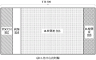
Under other wireless communication standards such as NR, ACK channel information as well as other information may be transmitted through the uplink structure shown in fig. 8 a. Fig. 8a shows an example uplink structure with a Transmission Time Interval (TTI)800, the TTI 800 including a region 806 for long uplink burst transmission (shown as "UL long burst 806"). The UL long burst (ULLB)806 may transmit information such as ACK, Channel Quality Indicator (CQI), or Scheduling Request (SR) information.
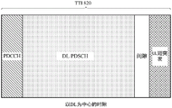
The duration of ULLB 806 may vary depending on how many symbols are used for Physical Downlink Control Channel (PDCCH)802, gap 804, and short uplink burst (shown as UL short burst (ULSB)808), as shown in fig. 8. For example, the UL long burst 806 may include several slots (e.g., 4 slots), where the duration of each slot may vary from 4 to 14 symbols. Fig. 8b also shows a downlink structure with TTI 820, which TTI 820 includes PDCCH, downlink Physical Downlink Shared Channel (PDSCH), gap, and ULSB. Similar to ULLB, the duration of DL PDSCH may also depend on the number of symbols used by PDCCH, gaps and ULSB.
Example Uplink Control Information (UCI) in short duration
As described above, the ULSB region (e.g., ULSB 808) may be 1 or 2 symbols, and a different method may be used to transmit UCI within the duration. For example, according to the "1-symbol" UCI design, 3-bit or more UCI may be transmitted using Frequency Division Multiplexing (FDM). For 1 or 2 bit ACKs (which may indicate an acknowledgement or lack of acknowledgement) and/or 1 bit Scheduling Requests (SRs), a bit sequence based design may be used. For example, the SR may be transmitted in a 1-bit sequence, i.e., on-off keying, and up to 12 users may be multiplexed per RB. For a 1-bit ACK, a 2-bit sequence may be used, and up to 6 users may be multiplexed per RB. For a 2-bit ACK, a 4-bit sequence may be used, and up to 3 users may be multiplexed per RB.
Typically, the assigned ACK and SR RBs are not adjacent to each other. When both need to be transmitted simultaneously, some problems may arise if each channel uses the same design. One is the Intermodulation (IMD) problem caused by discontinuous RB transmission. Another is the problem associated with increased peak-to-average power ratio (PAPR). Aspects of the present disclosure provide techniques for transmitting UCI having different types of information (e.g., 1 or 2-bit ACK and SR). In a particular aspect, the techniques described herein involve combining ACK and SR bits into a joint payload and sending the joint payload in the same RB, resulting in a low PAPR sequence and minimized IMD.
Fig. 9 illustrates example operations 900 for wireless communications by a transmitter in accordance with aspects of the disclosure. For example, operation 900 may be performed by a UE (e.g., UE 120).
Operations 900 begin at 902 by identifying resources within an uplink short burst (ULSB) region within a Transmission Time Interval (TTI) for transmitting at least a portion of Uplink Control Information (UCI) including at least one of one Scheduling Request (SR) bit and one or more Acknowledgement (ACK) bits for an acknowledgement or negative acknowledgement downlink transmission. At 904, the transmitter transmits UCI using the identified resources.
Fig. 9A illustrates a wireless communication device 900A, which may include various components (e.g., corresponding to functional module components) configured to perform operations for the techniques disclosed herein, such as one or more of the operations shown in fig. 9. The communication device 900A includes a processing system 914 coupled to a transceiver 912. The transceiver 912 is configured to transmit and receive signals for the communication device 900A via the antenna 913. The processing system 914 may be configured to perform processing functions for the communication device 900A, such as processing signals and the like.
The processing system 914 includes a processor 909 coupled to a computer-readable medium/memory 911 via a bus 921. In a particular aspect, the computer-readable medium/memory 911 is configured to store instructions that, when executed by the processor 909, cause the processor 909 to perform one or more of the operations shown in fig. 9 or perform other operations for performing the various techniques discussed herein.
In a particular aspect, the processing system 914 further includes an identification component 920 to perform one or more operations illustrated at 902 in fig. 9. In addition, processing system 914 includes a transmitting component 922 for performing one or more of the operations shown at 904 in fig. 9.
The identification component 920 and the transmission component 922 may be coupled to the processor 909 via a bus 921. In a particular aspect, the identifying component 920 and the transmitting component 922 may be hardware circuits. In a particular aspect, the identifying component 920 and the transmitting component 922 may be software components that execute and run on the processor 909.
As shown in fig. 10, in some aspects, SR and ACK bits may be transmitted in ULSB 808 using time division multiplexing. In some aspects, the SR may beSemi-statically configured (e.g., semi-static SR resources 1010) for use in a particular ULSB time resource (e.g., ULSB symbol 808)2) Is transmitted. However, since SRs are typically not delay sensitive (e.g., for enhanced mobile broadband (eMBB)), when the SR needs to be on the same short PUCCH symbol (e.g., ULSB symbol 808)2) When sent with an ACK, an SR may be sent from ULSB symbol 8082The semi-statically scheduled SR resource 1010 above is rescheduled to a different symbol with DCI. In other words, the need to send an ACK with an SR may be prioritized over the semi-static SR resources 1010 (e.g., the UE may skip sending an SR over the original semi-static SR resources 1010).
In some aspects, if the BS (e.g., 110) is intended to be on the same symbol (e.g., ULSB symbol 808) 2) Constant transmission of SR and ACK on, it may reconfigure the semi-static SR resources 1010. For example, the BS may configure the UE for semi-persistent independent transmissions with a short duration of 1 symbol (constant ACK over short duration).
As shown in fig. 10, a dynamic SR (e.g., a dynamically scheduled SR) may use a different symbol (e.g., ULSB symbol 808) in a short duration (e.g., ULSB 808) of a current time slot (e.g., time slot 1030, which may be half the duration of TTI 800 of fig. 8A)1) Or may be scheduled for the same or different symbols in a short duration in a later time slot (e.g., a time slot following time slot 1030). In some cases, the dynamic SR may use resources (e.g., resources 1016) in a long duration (e.g., ULLB 806) in a current time slot (e.g., time slot 1030) and/or the long SR may be transmitted as a short SR through repetition. In particular aspects, the SR may also have a time domain spread across multiple symbols and may occupy only a subset of the long duration (e.g., ULLB 806) in the current slot (e.g., slot 1030) or a later slot.
In some cases, the resource selection may be based on the value of the SR bit (e.g., one RB for a negative SR (SR-0), another RB for a positive SR (SR-1), or a set of sequences for a negative SR, another set of sequences for a positive SR). For each RB, the UE may use a normal sequence based ACK transmission (e.g., a 2-bit sequence for 1 ACK bit or a 4-bit sequence for 2 ACK bits).
As shown in fig. 11A, according to one technique (labeled technique 2A), the RB1104 for SR ═ 1 can be the same as the original SR RB (e.g., semi-static resource 1010). As shown in fig. 12A, the technique may utilize 8 resources (e.g., 4 sequences x 2 RBs) for 2-bit ACK + SR. In this way, the technique may use more resources for SR-only transmissions (2 or 4 bit sequences). The bit sequences may each have a different cyclic shift. Fig. 12A shows a circular representation of RBs 1102A and 1104A, each RB comprising several bit sequences. RB1102A includes a 4-bit sequence 1102A1-1102A4Carrying negative SR and ACK bits. RB1104A includes a 4-bit sequence for carrying positive SR as well as ACK bits. For example, RB1104A includes a bit sequence that indicates a positive SR and two ACK bits. Each bit sequence representing a different acknowledgement scenario.
For example, bit sequence 1104A1A positive SR and two ACK bits corresponding to two non-acknowledgements (e.g., one per codeword) may be indicated. The bit sequence is shown as being associated with bit sequence 1104A2-1104A4This is different because the sequence is the same as the SR-only bit sequence (e.g., when ACK/NACK is DTX). Thus, with respect to bit sequence 1104A1The BS cannot distinguish whether the bit sequence is an SR + DTX bit sequence or an SR + NACK/NACK bit sequence (e.g., the BS cannot perform DTX detection). This is for example compared with the bit sequence 1104B1In contrast, the bit sequence is in a different RB compared to other bit sequences, so that the BS can perform DTX detection.
Now talk of bit sequence 1104A2Bit sequence 1104A2A positive SR and two ACK bits corresponding to one acknowledgement associated with one codeword and a non-acknowledgement associated with another codeword may be indicated. Bit sequence 1104A3A positive SR and two ACK bits corresponding to one non-acknowledgement associated with one codeword and an acknowledgement associated with another codeword may be indicated. Bit sequence 1104A4A positive SR and two ACK bits corresponding to two acknowledgements may be indicated. As shown, in a particular aspect, the bit sequence 1104A2And 1104A3The ACK may be allocated to 1 bit or reserved when the SR is transmitted separately. Also, in a particular aspect, 1104A even when the SRs are transmitted individually 4May also be reserved.
As shown in fig. 11B, according to another technique (labeled technique 2B), the RB (e.g., RB 1106) for a positive SR (SR ═ 1) may be different from the original SR RB 1104 (e.g., semi-static resource 1010). As shown in fig. 12B, technique 2B may utilize 9 resources for 2 bits of ACK + SR (e.g., 1 bit sequence in RB 1104B for SR + DTX (discontinuous transmission) and 4 bit sequences x 2 for 2 bits of ACK + SR) or 5 resources for 1 bit of ACK + SR (e.g., 1 bit sequence in RB 1104B for SR + DTX (discontinuous transmission) and 2 bit sequences x 2 for 1 bit of ACK + SR). For the example of ACK + SR with 2 bits, as shown, RB 1102B includes a four bit sequence 1102B1-1102B4And RB 1106 includes four bit sequences 11061-11064And RB 1104B includes a 1-bit sequence 1104B1. In particular aspects, one or more bit sequences may be derived from the same base bit sequence with different cyclic shifts. As used herein, DTX refers to discontinuous transmission (e.g., when the UE does not detect any transmission and thus has no ACK/NACK information to send). As shown in fig. 12B, technique 2B may require only 1 resource for SR-only transmission (e.g., 1 bit sequence 1104B in RB 1104B) 1). Technique 2B may allow DTX to be detected when SR 1 (e.g., if SR 1 is detected in the original SR resources (e.g., RB 1104B corresponding to semi-static SR resources 1010 of fig. 10), this may be considered a DTX + SR 1 indication). In both technology 2A and technology 2B, if no bit sequence is detected in all resources, this may be considered to be DTX + SR ═ 0.
In a particular aspect, when there is an ACK bit to send, the UE may identify one RB (e.g., RB 1106 or 1102B in fig. 12B) for sending the SR bit and one or more ACK bits. The selection of the RB may depend on the value of the SR bit (e.g., where SR is positive or negative). However, when there are no ACK bits to send, the UE may identify a different RB (e.g., RB 1104B) for sending the SR bit without sending any ACK bits.
In the case where there are ACK bits to be transmitted and an RB is selected for transmitting the SR bits and the one or more ACK bits, the above sequence-based design is used for transmitting the SR bits and the one or more ACK bits. For example, as described above, when ACK is only 1 bit, two bit sequences may be identified to transmit the ACK bit and the positive SR, and the other two bit sequences may be identified to transmit the ACK bit and the negative SR. In another example, as described above, when ACK is 2 bits, four bit sequences may be identified to transmit ACK bits and positive SRs (e.g., SR ═ 1 and ACK-NACK, ACK-ACK, NACK-ACK, and NACK-NACK), and another four bit sequences may be identified to transmit ACK bits and negative SRs (e.g., SR ═ 0 and ACK-NACK, ACK-ACK, NACK-ACK, and NACK-NACK).
As described above, in some aspects, when there are no ACK bits (e.g., DTX: when the UE has not detected any content and thus has no ACK/NACK information to send), the UE may identify an RB (e.g., RB 1104B) that sends an SR using only 1 sequence without sending any ACK bits. In a particular aspect, the SR transmitted on RB 1104B may be positive.
As shown in fig. 13, in some cases, UCI (SR and ACK) may be sent via parallel transmission with adjacent RBs (e.g., in FDM in the same symbol). For example, adjacent RBs 1302 and 1304 may be used to transmit UCI in the same ULSB symbol. Using this technique may result in no intermodulation leakage, low peak-to-average power ratio (PAPR), and relatively simple transmit and receive processing. However, this technique may result in power splitting between the SR and ACK bits, which may have the potential for performance loss compared to individual transmissions. Such performance may be acceptable, for example, if the UE is not link budget limited.
However, in some aspects, the technique (with SR and ACK FDM in the same symbol as shown in fig. 13) may be Power Headroom (PHR) dependent. For example, if both the UE and the BS can obtain the latest PHR report, and the latest PHR indicates a power (e.g., X ═ 6dB) that is at least a certain threshold (e.g., X dB) below the maximum power, the UE may use parallel transmission (the technique shown in fig. 13). On the other hand, if the latest PHR indicates a power X dB less than the maximum power, the UE may use a bundled ACK. For example, in these aspects, the UE may combine 2 bits of ACKs into 1 bit and transmit with the SR on the ACK resources (e.g., using a 4 bit sequence in 1 RB).
There are various options if power splitting is performed for parallel transmission of SR and ACK. For example, if SR is 0, all power may be allocated to ACK. On the other hand, if SR 1: y% of power may be allocated to the SR and 1-Y% of power may be allocated to the 2-bit ACK. Y may be selected according to objectives such as:
y is 50: equal power split on SR and ACK;
y33.3: 1/3 on SR, 2/3 on ACK, so that the power per bit is the same;
y is 0: the SR is discarded; or
Y is 100: the ACK is discarded.
Fig. 14A illustrates another technique for transmitting UCI in the ULSB region. In particular aspects, the techniques may utilize resource selection that may avoid the need for power splitting between 2 bits of the ACK to be used for 2-bit ACKs. Using this technique, the 2 nd bit of the ACK may be transmitted in a 2-bit sequence over one RB of a first value of the 1 st bit for the ACK (e.g., 1 st ACK ═ 0) and over another RB of a second value of the 1 st bit for the ACK (e.g., 1 st ACK ═ 1). For example, RB 1402A includes a two bit sequence for the first bit of an ACK having a value of 1, and RB 1404A includes a two bit sequence for the first bit of an ACK having a value of 1.
Fig. 14B shows another example similar to fig. 12B, where the SR may be transmitted in a manner that allows for DTX indication. For example, RB 1402B includes a four bit sequence for the first bit of the ACK having a value of 0. The four bit sequences of RB 1402B include two bit sequences for negative SRs and two bit sequences for positive SRs. RB 1404B includes a four bit sequence for the first bit of the ACK having a value of 1. 1404B include two bit sequences for negative SRs and two bit sequences for positive SRs. RB 1406 includes a bit sequence for SR + DTX.
In some cases, different UEs may have different ULLB durations. According to certain aspects of the present disclosure, ULLB regions of different UEs may be multiplexed in the same RB with different long durations.
Fig. 15 illustrates example operations 1500 for wireless communications by a transmitter in accordance with aspects of the disclosure. For example, operation 1500 may be performed by a UE. The UEs are multiplexed in the same RB with different durations. There is a common uplink region, which is an overlapping portion between UEs. There are also additional regions from the UE that have longer durations. The additional regions may be present on either or both sides of the common region.
The operations 1500 begin at 1502 with: extended resources are identified that are dynamically available for uplink transmission by the UE adjacent to a common uplink region within a Transmission Time Interval (TTI). At 1504, the transmitter transmits an uplink transmission using the extended resource.
Fig. 15A illustrates a wireless communication device 1500A, which may include various components (e.g., corresponding to functional module components) configured to perform operations, such as one or more of the operations illustrated in fig. 15, for the techniques disclosed herein. The communication device 1500A includes a processing system 1514 coupled to a transceiver 1512. The transceiver 1512 is configured to transmit and receive signals for the communication device 1500A via the antenna 1513. The processing system 1514 may be configured to perform processing functions for the communication device 1500A, such as processing signals and the like.
The processing system 1514 includes a processor 1509 coupled to a computer-readable medium/memory 1511 via a bus 1521. In a particular aspect, the computer-readable medium/memory 1511 is configured to store instructions that, when executed by the processor 1509, cause the processor 1509 to perform one or more of the operations shown in fig. 15 or to perform other operations for performing the various techniques discussed herein.
In a particular aspect, the processing system 1514 further includes an identification component 1520 for performing one or more operations shown at 1502 in fig. 15. Additionally, processing system 1514 includes a transmit component 1522 for performing one or more of the operations shown at 1504 in fig. 15.
The identification component 1520 and the sending component 1522 may be coupled to the processor 1509 via a bus 1521. In a particular aspect, the identifying component 1520 and the sending component 1522 can be hardware circuits. In a particular aspect, the identification component 1520 and the sending component 1522 may be software components that execute and run on the processor 1509.
Fig. 16 shows an example regarding UE multiplexing for UEs with different ULLB durations. In some cases, different UEs may have different ULLB durations. For example, one UE may have a ULLB that includes only the common region 1602A. However, another UE may have a ULLB including two regions: a common region 1602B and an additional region 1604. Further, some UEs may support dynamic extension, while some UEs may not support dynamic extension. In some cases, if time domain spreading is performed, the resources may be divided into Code Division Multiplexing (CDM) groups into the two common and additional regions (e.g., common region 1602B and additional region 1604). The additional area includes extended resources. For example, the common region 1602 may be used to ensure orthogonality, and the first CDM group in this region may start at the same symbol where the common region 1602 starts. For additional region 1604, additional CDM groups may be defined (e.g., this may be for only UEs with additional regions), and spreading may be prohibited in this additional region 1604. In some cases, a hop location 1606 for hopping in the additional region 1604 may be calculated based on the common region 1602 (e.g., the additional region may hop along with neighboring common regions).
According to particular aspects of the present disclosure, ACK resources may be determined via implicit mapping, as shown in fig. 17. In NR, the ACK channel may have different payloads (e.g., 1 or 2 bits or 3 or more bits). In some cases, the number of ACK RBs may also range from 1 to a number of RBs. The resource regions for 1 RB or RBs may or may not overlap (as shown in fig. 17). For example, in symbol 1700A, region 1702A for a 1-RB ACK does not overlap region 1704B for a 2-RB ACK. In another example, in symbol 1700B, region 1702B for a 1-RB ACK overlaps with region 1704B for a 2-RB ACK.
In some cases, implicit mapping from PDCCH to ACK resources may help save DCI overhead. According to one technique, the UE may perform implicit mapping for 1 or 2 bits of the ACK and explicit signaling for the remaining bits of the ACK bits for a long (e.g., ULLB) duration and a short (e.g., ULSB) duration with only 1-RB allocations. In some cases, the long ACK and the short ACK may use different resource pools. For long PUCCH, 1 or 2 ACK bits may use the same number of resources with different modulations, so that the mapping may not depend on the payload size. For short PUCCH, 1 or 2 ACK bits may use different number of resources (e.g., 1 bit may use 2 shifts, 2 bits may use 4 shifts), so that the mapping rule may depend on the payload size. For a short PUCCH, the mapping may determine only the first resource, and the remaining resources (e.g., the second resource for 1 bit, and the other 3 resources for 2 bits) may be derived based on the first resource.
According to another technique, the UE may perform implicit mapping for 1 or 2 bits of ACK and explicit signaling for the remaining bits of ACK bits in long and short durations with any number of RB allocations. Resource regions for different numbers of RBs may be overlapping or non-overlapping (e.g., fig. 17). In some aspects, for non-overlapping regions, the number of RBs may be derived based on a mapping function. For overlapping regions, the number of RBs may be explicitly signaled, and the mapping function may depend on the number of RBs allocated.
In some aspects, the UE may perform implicit mapping for any number of ACKs in long and short durations with only 1-RB allocations and explicit signaling for the remaining bits of the ACK bits. In these aspects, the mapping function used to perform the implicit mapping may be based on the payload size.
In some aspects, the UE may perform implicit mapping for any number of ACKs in long and short durations with any number of RB allocations and explicit signaling for the remaining bits of the ACK bits. In these aspects, the mapping function used to perform the implicit mapping may be based on the payload size and the number of RBs.
According to particular aspects of the present disclosure, there may be long and short durations that are cell-specific and UE-specific. In some aspects, the cell-specific short duration may be configured semi-statically (e.g., so all neighboring cells may configure the same short duration in the same time slot to avoid mixed interference).
In some aspects, a cell-specific long duration may be derived (e.g., a cell-specific short duration-semi-static PDCCH duration-GAP (GAP) that is slot duration-semi-static). In these aspects, the cell-specific PDCCH region may be semi-statically configured and the actual PDCCH region may be dynamically indicated with a control format indicator, CFI.
In some aspects, the UE-specific short duration may be a subset of the cell-specific short duration. For example, the cell-specific short duration may be 2 symbols long, and the UE-specific short duration may be 1 symbol long. In some aspects, the UE-specific short duration may not exceed the cell-specific short duration to avoid mixed interference.
The UE-specific long duration may be a subset of the cell-specific long duration. For example, the cell-specific long duration may be 11 symbols, and the UE-specific long duration may be 4 symbols.
In some cases, a UE-specific long duration extension may be available. According to one technique, there may be no dynamic extensions such that the UE-specific long duration may not exceed the cell-specific long duration. This may be controlled by the BS with a start symbol index/end symbol index. According to another technique, the UE-specific long duration may exceed the cell-specific long duration with dynamic spreading. This may be controlled by the BS with a start symbol index/end symbol index. The common area (e.g., common area 1602 shown in fig. 16) may be determined using a long duration dedicated to a cell.
The methods disclosed herein comprise one or more steps or actions for achieving the described method. The method steps and/or actions may be interchanged with one another without departing from the scope of the claims. In other words, unless a specific order of steps or actions is specified, the order and/or use of specific steps and/or actions may be modified without departing from the scope of the claims.
As used herein, a phrase referring to "at least one of" a list of items refers to any combination of those items, including a single member. By way of example, "at least one of a, b, or c" is intended to encompass a, b, c, ab, ac, bc, and abc, as well as any combination of a plurality of the same elements (e.g., any other ordering of aa, aaa, aab, aac, abc, bb, bbb, bbc, cc, and ccc, or a, b, and c).
As used herein, the term "determining" encompasses a wide variety of actions. For example, "determining" can include calculating, evaluating, processing, deriving, investigating, looking up (e.g., looking up in a table, a database or another data structure), verifying, etc. Also, "determining" may include receiving (e.g., receiving information), accessing (e.g., accessing data in a memory), and the like. Also, "determining" may include resolving, selecting, choosing, establishing, and the like.
The previous description is provided to enable any person skilled in the art to practice the various aspects described herein. Various modifications to these aspects will be readily apparent to those skilled in the art, and the generic principles defined herein may be applied to other aspects. Thus, the claims are not intended to be limited to the aspects shown herein, but is to be accorded the full scope consistent with the language claims, wherein reference to an element in the singular is not intended to mean "one and only one" (unless specifically so stated), but rather "one or more. The term "some" means one or more unless specifically stated otherwise. All structural and functional equivalents to the elements of the various aspects described throughout this disclosure that are known or later come to be known to those of ordinary skill in the art are expressly incorporated herein by reference and are intended to be encompassed by the claims. Moreover, nothing disclosed herein is intended to be dedicated to the public regardless of whether such disclosure is explicitly recited in the claims. Unless an element of a claim is explicitly recited using the phrase "functional module" or in the case of a method claim the element is recited using the phrase "step for.
The various operations of the methods described above may be performed by any suitable means that can perform the corresponding functions. These units may include various hardware and/or software components and/or modules, including but not limited to circuits, Application Specific Integrated Circuits (ASICs), or processors. Generally, where there are operations illustrated in the figures, those operations may have corresponding respective functional module components with similar numbering.
For example, the means for transmitting and/or the means for receiving may include one or more of: a transmit processor 420, a TX MIMO processor 430, a receive processor 438 or antenna 434 of the base station 110, and/or a transmit processor 464, a TX MIMO processor 466, a receive processor 458 or antenna 452 of the user equipment 120. Further, the means for generating, the means for multiplexing, and/or the means for applying may comprise one or more processors, such as controller/processor 440 of base station 110 and/or controller/processor 480 of user equipment 120.
The various illustrative logical blocks, modules, and circuits described in connection with the disclosure may be implemented or performed with a general purpose processor, a Digital Signal Processor (DSP), an Application Specific Integrated Circuit (ASIC), a field programmable gate array signal (FPGA) or other Programmable Logic Device (PLD), discrete gate or transistor logic, discrete hardware components, or any combination thereof designed to perform the functions described herein. A general purpose processor may be a microprocessor, but in the alternative, the processor may be any commercially available processor, controller, microcontroller or state machine. A processor may also be implemented as a combination of computing devices, e.g., a combination of a DSP and a microprocessor, a plurality of microprocessors, one or more microprocessors in conjunction with a DSP core, or any other such configuration.
If implemented in hardware, an example hardware configuration may include a processing system in the wireless node. The processing system may be implemented with a bus architecture. The buses may include any number of interconnecting buses and bridges depending on the specific application of the processing system and the overall design constraints. The bus may link together various circuits including the processor, the machine-readable medium, and the bus interface. A bus interface may be used to connect a network adapter or the like to the processing system via the bus. The network adapter may be used to implement signal processing functions of the PHY layer. In the case of a user terminal 120 (refer to fig. 1), a user interface (e.g., a keyboard, a display, a mouse, a joystick, etc.) may also be connected to the bus. The bus may also link various other circuits known in the art, such as timing sources, peripherals, voltage regulators, power management circuits, and the like, which, because well known, will not be described again. The processor may be implemented with one or more general-purpose and/or special-purpose processors. Examples include microprocessors, microcontrollers, DSP processors, and other circuits that can execute software. Those skilled in the art will recognize how best to implement the described functionality for a processing system, depending on the particular application and the overall design constraints imposed on the overall system.
If implemented in software, the functions may be stored on or transmitted over as one or more instructions or code on a computer-readable medium. Software shall be construed broadly to mean instructions, data, or any combination thereof, whether referred to as software, firmware, middleware, microcode, hardware description language, or otherwise. Computer-readable media includes both computer storage media and communication media including any medium that facilitates transfer of a computer program from one place to another. The processor may be responsible for managing the bus and general processing, including the execution of software modules stored on the machine-readable storage medium. A computer readable storage medium may be coupled to the processor such that the processor can read information from, and write information to, the storage medium. In the alternative, the storage medium may be integral to the processor. By way of example, the machine-readable medium may comprise a transmission line, a carrier wave modulated by data, and/or a computer-readable storage medium separate from the wireless node and having instructions stored thereon, all of which may be accessed by the processor through a bus interface. Alternatively or additionally, the machine-readable medium or any portion thereof may be integrated into a processor, such as might be the case with a cache and/or a general register file. Examples of a machine-readable storage medium may include, for example, RAM (random access memory), flash memory, ROM (read only memory), PROM (programmable read only memory), EPROM (erasable programmable read only memory), EEPROM (electrically erasable programmable read only memory), registers, a magnetic disk, an optical disk, a hard drive, or any other suitable storage medium or any combination thereof. The machine-readable medium may be embodied in a computer program product.
A software module may comprise a single instruction, or many instructions, and may be distributed over several different code segments, among different programs, and across multiple storage media. The computer readable medium may include a plurality of software modules. The software modules may include instructions that, when executed by an apparatus, such as a processor, cause a processing system to perform various functions. The software modules may include a transmission module and a reception module. Each software module may reside on a single storage device or be distributed across multiple storage devices. For example, when a triggering event occurs, a software module may be loaded from a hard disk drive into RAM. During execution of the software module, the processor may load some instructions into the cache to increase access speed. One or more cache lines may then be loaded into a general register file for execution by the processor. When reference is made below to the functionality of a software module, it will be understood that such functionality is implemented by a processor when executing instructions from the software module.
Also, any connection is properly termed a computer-readable medium. For example, if the software is transmitted from a website, server, or other remote source using a coaxial cable, fiber optic cable, twisted pair, Digital Subscriber Line (DSL), or wireless technologies such as Infrared (IR), radio, and microwave, then the coaxial cable, fiber optic cable, twisted pair, DSL, or wireless technologies such as infrared, radio, and microwave are included in the definition of medium. Disk and disc, as used herein, includes Compact Disc (CD), laser disc, optical disc, Digital Versatile Disc (DVD), floppy disk and  Disks, where a disk usually reproduces data magnetically, and disks reproduce data optically. Thus, in some aspects, computer-readable media may comprise non-transitory computer-readable media (e.g., tangible media). Additionally, for other aspects, the computer-readable medium may comprise a transitory computer-readable medium (e.g., a signal). Combinations of the above should also be included within the scope of computer-readable media.
Accordingly, particular aspects may include a computer program product for performing the operations presented herein. For example, such a computer program product may include a computer-readable medium having instructions stored (and/or encoded) thereon, the instructions being executable by one or more processors to perform the operations described herein.
Further, it should be appreciated that modules and/or other suitable means for performing the methods and techniques described herein may be downloaded and/or otherwise obtained by a user terminal and/or base station as applicable. For example, such a device may be coupled to a server in order to communicate means for performing the methods described herein. Alternatively, the various methods described herein may be provided via a storage unit (e.g., RAM, ROM, a physical storage medium such as a Compact Disc (CD) or floppy disk) such that the user terminal and/or base station may obtain the various methods upon coupling or providing the storage unit to the device. Further, any other suitable technique for providing the methods and techniques described herein to a device may be utilized.
It is to be understood that the claims are not limited to the precise configuration and components shown above. Various modifications, changes and variations may be made in the arrangement, operation and details of the methods and apparatus described above without departing from the scope of the claims.
Claims (44)
1. A method for wireless communications by a transmitter, comprising:
identifying, within an uplink short burst (ULSB) region having one or two symbols within a Transmission Time Interval (TTI), resources for transmitting at least a portion of Uplink Control Information (UCI) comprising at least one of one Scheduling Request (SR) bit and one or more Acknowledgement (ACK) bits for acknowledgement or negative acknowledgement downlink transmission, wherein the SR bit and the one or more ACK bits are frequency division multiplexed for transmission in different resource blocks in the same symbol; and
transmitting the UCI using the identified resources.
2. The method of claim 1, wherein the identifying comprises:
identifying a first Resource Block (RB) within the ULSB for transmitting the SR bits and the one or more ACK bits; or
Identifying a second RB for transmitting the SR bits without transmitting the one or more ACK bits.
3. The method of claim 2, wherein the UCI comprises the SR bits, and wherein the first RB is identified based on a value of the SR bits.
4. The method of claim 3, wherein the value of the SR bit corresponds to a negative SR or a positive SR.
5. The method of claim 2, wherein identifying the first Resource Block (RB) further comprises:
identifying a first set of at least two bit sequences to transmit ACK bits of the one or more ACK bits and the SR bits having a first value using the first RB; and
identifying a second set of at least two bit sequences to use to transmit the ACK bit of the one or more ACK bits and the SR bit having a second value using the first RB.
6. The method of claim 2, wherein identifying the first Resource Block (RB) further comprises:
identifying a first set of at least four bit sequences to use the first RB to transmit two ACK bits of the one or more ACK bits and the SR bit having a first value; and
identifying a second set of at least four bit sequences to use to transmit the two of the one or more ACK bits and the SR bit having a second value using the first RB.
7. The method of claim 2, wherein the second RB is identified when there is no ACK bit to transmit, and wherein a value of the SR bit is for a positive SR.
8. The method of claim 1, wherein the identifying comprises:
identifying a first symbol in the ULSB that is semi-statically configured for transmitting the SR bits; and
transmitting at least one ACK bit of the one or more ACK bits using the first symbol.
9. The method of claim 8, further comprising:
using a second symbol for transmitting the SR bits, wherein the second symbol is located in one of: the ULSB, an uplink long burst (ULLB) region of the TTI having greater than two symbols, or a subsequent TTI.
10. The method of claim 1, wherein the identifying comprises:
identifying a first Resource Block (RB) within the ULSB for transmitting the SR bit if the SR bit is a first value; or
Identifying a second RB within the ULSB for transmitting the SR bit if the SR bit is a second value.
11. The method of claim 10, wherein:
The first value of the SR bit is for a positive SR and the second value of the SR bit is for a negative SR.
12. The method of claim 10, wherein the identifying comprises:
identifying at least four bit sequences to transmit at least two ACK bits when the SR bits are transmitted using the first RB or the second RB.
13. The method of claim 12, wherein the identifying further comprises: identifying, for the SR bit that is the first value, at least one of the at least four bit sequences for transmitting the SR bit without transmitting an ACK bit using the first RB.
14. The method of claim 10, wherein the identifying comprises:
identifying a bit sequence in an RB for transmitting the SR bit without transmitting an ACK bit; or
Identifying at least two RBs for transmitting the SR bit with at least two of the one or more ACK bits; and
identifying at least four bit sequences to transmit the at least two of the one or more ACK bits when the SR bit is transmitted using one of the at least two RBs.
15. The method of claim 1, wherein:
the SR bit and the one or more ACK bits are transmitted in adjacent RBs.
16. The method of claim 1, further comprising:
splitting power between the SR bits and the one or more ACK bits.
17. The method of claim 1, wherein:
the SR bits and the one or more ACK bits are sent in the same symbol using FDM only when a Power Headroom (PHR) is above a threshold.
18. The method of claim 1, wherein:
the SR bit and the one or more ACK bits are sent in the same symbol in ACK resources with the one or more ACK bits bundled into a single bit when a Power Headroom (PHR) is below a threshold.
19. The method of claim 1, wherein the identifying comprises:
identifying a first Resource Block (RB) within the ULSB that is used for the first ACK bit of the one or more ACK bits if the first ACK bit is a first value; or
Identifying a second RB within the ULSB that is used for the first ACK bit if the first ACK bit is a second value.
20. The method of claim 19, wherein the identifying comprises:
identifying at least four bit sequences to transmit at least two of the one or more ACK bits when transmitting an SR using the first RB or the second RB.
21. The method of claim 19, wherein the identifying comprises:
identifying one RB for transmitting the SR bit without transmitting an ACK bit; or
Identifying at least two RBs for transmitting the SR bits with at least the first of the one or more ACK bits.
22. An apparatus, comprising:
a non-transitory memory containing executable instructions; and
a processor in data communication with the memory and configured by executing the instructions to:
identifying, within an uplink short burst (ULSB) region having one or two symbols within a Transmission Time Interval (TTI), resources for transmitting at least a portion of Uplink Control Information (UCI) comprising at least one of one Scheduling Request (SR) bit and one or more Acknowledgement (ACK) bits for acknowledgement or negative acknowledgement downlink transmission, wherein the SR bit and the one or more ACK bits are frequency division multiplexed for transmission in different resource blocks in the same symbol; and
Transmitting the UCI using the identified resources.
23. The apparatus of claim 22, wherein the processor configured to identify the resource is further configured to:
identifying a first Resource Block (RB) within the ULSB for transmitting the SR bits and the one or more ACK bits; or
Identifying a second RB for transmitting the SR bits without transmitting the one or more ACK bits.
24. The apparatus of claim 23, wherein the UCI includes the SR bit, and wherein the first RB is identified based on a value of the SR bit.
25. The apparatus of claim 24, wherein the value of the SR bit corresponds to a negative SR or a positive SR.
26. The apparatus of claim 23, wherein the processor configured to identify the first RB is further configured to:
identifying a first set of at least two bit sequences to transmit ACK bits of the one or more ACK bits and the SR bits having a first value using the first RB; and
identifying a second set of at least two bit sequences to use to transmit the ACK bit of the one or more ACK bits and the SR bit having a second value using the first RB.
27. The apparatus of claim 23, wherein the processor configured to identify the first RB is further configured to:
identifying a first set of at least four bit sequences to transmit two of the one or more ACK bits and the SR bit having a first value using the first RB; and
identifying a second set of at least four bit sequences to use to transmit the two of the one or more ACK bits and the SR bit having a second value using the first RB.
28. The apparatus of claim 23, wherein the second RB is identified when there is no ACK bit to transmit, and wherein a value of the SR bit is for a positive SR.
29. The apparatus of claim 22, wherein the processor configured to identify the resource is further configured to:
identifying a first symbol in the ULSB that is semi-statically configured for transmitting the SR bits; and
transmitting at least one ACK bit of the one or more ACK bits using the first symbol.
30. The apparatus of claim 29, wherein the processor is further configured to:
Using a second symbol for transmitting the SR bits, wherein the second symbol is located in one of: the ULSB, an uplink long burst (ULLB) region of the TTI having greater than two symbols, or a subsequent TTI.
31. The apparatus of claim 22, wherein the processor configured to identify the resource is further configured to:
identifying a first Resource Block (RB) within the ULSB for transmitting the SR bit if the SR bit is a first value; or
Identifying a second RB within the ULSB for transmitting the SR bit if the SR bit is a second value.
32. The apparatus of claim 31, wherein:
the first value of the SR bit is for a positive SR and the second value of the SR bit is for a negative SR.
33. The apparatus of claim 31, wherein the processor configured to identify the resource is further configured to:
identifying at least four bit sequences to transmit at least two ACK bits when the SR bits are transmitted using the first RB or the second RB.
34. The apparatus of claim 33, wherein the processor configured to identify the resource is further configured to:
Identifying, for the SR bit that is the first value, at least one of the at least four bit sequences for transmitting the SR bit without transmitting an ACK bit using the first RB.
35. The apparatus of claim 31, wherein the processor configured to identify the resource is further configured to:
identifying a bit sequence in an RB for transmitting the SR bit without transmitting an ACK bit; or
Identifying at least two RBs for transmitting the SR bit with at least two of the one or more ACK bits; and
identifying at least four bit sequences to transmit the at least two of the one or more ACK bits when the SR bit is transmitted using one of the at least two RBs.
36. The apparatus of claim 22, wherein:
the SR bit and the one or more ACK bits are transmitted in adjacent RBs.
37. The apparatus of claim 22, the processor further configured to:
splitting power between the SR bits and the one or more ACK bits.
38. The apparatus of claim 22, wherein:
The SR bits and the one or more ACK bits are sent in the same symbol using FDM only when a Power Headroom (PHR) is above a threshold.
39. The apparatus of claim 22, wherein:
the SR bit and the one or more ACK bits are sent in the same symbol in ACK resources with the one or more ACK bits bundled into a single bit when a Power Headroom (PHR) is below a threshold.
40. The apparatus of claim 22, wherein the processor configured to identify the resource is further configured to:
identifying a first Resource Block (RB) within the ULSB that is used for the first ACK bit of the one or more ACK bits if the first ACK bit is a first value; or
Identifying a second RB within the ULSB that is used for the first ACK bit if the first ACK bit is a second value.
41. The apparatus of claim 40, wherein the processor configured to identify the resource is further configured to:
identifying at least four bit sequences to convey at least two of the one or more ACK bits when transmitting SR using the first RB or the second RB.
42. The apparatus of claim 40, wherein the processor configured to identify the resource is further configured to:
identifying one RB for transmitting the SR bit without transmitting an ACK bit; or
Identifying at least two RBs for transmitting the SR bit with at least the first of the one or more ACK bits.
43. An apparatus, comprising:
means for identifying resources within an uplink short burst (ULSB) region having one or two symbols within a Transmission Time Interval (TTI) for transmitting at least a portion of Uplink Control Information (UCI) comprising at least one of one Scheduling Request (SR) bit and one or more Acknowledgement (ACK) bits for acknowledgement or negative acknowledgement downlink transmission, wherein the SR bit and the one or more ACK bits are frequency division multiplexed for transmission in different resource blocks in the same symbol; and
means for transmitting the UCI using the identified resources.
44. A non-transitory computer readable medium having stored thereon instructions for performing a method comprising:
identifying, within an uplink short burst (ULSB) region having one or two symbols within a Transmission Time Interval (TTI), resources for transmitting at least a portion of Uplink Control Information (UCI) comprising at least one of one Scheduling Request (SR) bit and one or more Acknowledgement (ACK) bits for acknowledgement or negative acknowledgement downlink transmission, wherein the SR bit and the one or more ACK bits are frequency division multiplexed for transmission in different resource blocks in the same symbol; and
Transmitting the UCI using the identified resources.
Applications Claiming Priority (5)
| Application Number | Priority Date | Filing Date | Title |
|---|---|---|---|
| US201762544750P | 2017-08-11 | 2017-08-11 | |
| US62/544,750 | 2017-08-11 | ||
| US16/056,073 | 2018-08-06 | ||
| US16/056,073 US10911189B2 (en) | 2017-08-11 | 2018-08-06 | Uplink control information (UCI) in short duration |
| PCT/US2018/045634 WO2019032599A2 (en) | 2017-08-11 | 2018-08-07 | Uplink control information (uci) in short duration |
Publications (2)
| Publication Number | Publication Date |
|---|---|
| CN111034082A CN111034082A (en) | 2020-04-17 |
| CN111034082B true CN111034082B (en) | 2022-07-12 |
Family
ID=63449659
Family Applications (1)
| Application Number | Title | Priority Date | Filing Date |
|---|---|---|---|
| CN201880051014.2A Active CN111034082B (en) | 2017-08-11 | 2018-08-07 | Uplink Control Information (UCI) in short duration |
Country Status (9)
| Country | Link |
|---|---|
| US (1) | US10911189B2 (en) |
| EP (2) | EP3665808A2 (en) |
| JP (2) | JP7455739B2 (en) |
| KR (1) | KR20200035405A (en) |
| CN (1) | CN111034082B (en) |
| BR (1) | BR112020002614A2 (en) |
| SG (1) | SG11202000177VA (en) |
| TW (1) | TWI796347B (en) |
| WO (1) | WO2019032599A2 (en) |
Families Citing this family (2)
| Publication number | Priority date | Publication date | Assignee | Title |
|---|---|---|---|---|
| US10123349B2 (en) | 2015-07-09 | 2018-11-06 | Qualcomm Incorporated | Low latency physical uplink control channel with scheduling request and channel state information |
| CN111083782B (en) * | 2018-10-19 | 2023-09-08 | 荣耀终端有限公司 | User equipment, method and device in base station for wireless communication |
Citations (1)
| Publication number | Priority date | Publication date | Assignee | Title |
|---|---|---|---|---|
| CN102111886A (en) * | 2010-07-02 | 2011-06-29 | 电信科学技术研究院 | Method and device for transmitting uplink control information |
Family Cites Families (16)
| Publication number | Priority date | Publication date | Assignee | Title |
|---|---|---|---|---|
| CN101431774B (en) * | 2008-11-28 | 2010-09-29 | 华为技术有限公司 | Resource allocation method and apparatus for physical uplink control channel, and base station |
| WO2010123893A1 (en) * | 2009-04-22 | 2010-10-28 | Interdigital Patent Holdings, Inc. | Method and apparatus for transmitting uplink control information for carrier aggregated spectrums |
| CN102158981B (en) * | 2010-02-11 | 2016-06-22 | 中兴通讯股份有限公司 | A kind of uplink data transmission method based on competition and system |
| KR101605843B1 (en) | 2010-11-02 | 2016-03-23 | 퀄컴 인코포레이티드 | Hybrid automatic repeat request feedback transmission in a multi component-carrier communication system using scheduling request resources |
| US8830883B2 (en) * | 2010-11-16 | 2014-09-09 | Qualcomm Incorporated | Method and apparatus for improving acknowledgement/negative acknowledgement feedback |
| CN108540169B (en) * | 2013-11-11 | 2021-04-09 | 华为技术有限公司 | Frequency hopping processing method and device |
| US10123349B2 (en) | 2015-07-09 | 2018-11-06 | Qualcomm Incorporated | Low latency physical uplink control channel with scheduling request and channel state information |
| US20170135090A1 (en) * | 2015-11-11 | 2017-05-11 | Sharp Laboratories Of America, Inc. | Systems and methods for uplink control information reporting with license-assisted access (laa) uplink transmissions |
| US10123347B2 (en) * | 2015-12-04 | 2018-11-06 | Qualcomm Incorporated | Method and apparatus for decoupling uplink latency using common uplink burst in TDD subframe structure |
| US10038544B2 (en) * | 2015-12-09 | 2018-07-31 | Qualcomm Incorporated | Multiple access for users with different modes in a common uplink burst in a time division duplex subframe structure |
| US20190312669A1 (en) * | 2016-03-29 | 2019-10-10 | Lg Electronics Inc. | Method for transmitting channel state information in wireless communication system, and apparatus therefor |
| US10277367B2 (en) * | 2016-04-01 | 2019-04-30 | Motorola Mobility Llc | Method and apparatus for scheduling uplink transmissions with reduced latency |
| WO2018141213A1 (en) * | 2017-02-03 | 2018-08-09 | Telefonaktiebolaget Lm Ericsson (Publ) | Method and device for performing uplink transmission |
| KR102423211B1 (en) * | 2017-03-23 | 2022-07-20 | 가부시키가이샤 엔티티 도코모 | User terminal and wireless communication method |
| US11736259B2 (en) * | 2017-05-03 | 2023-08-22 | Interdigital Patent Holdings, Inc. | Methods, systems, and apparatus for transmitting uplink control information |
| AU2018313837B2 (en) * | 2017-08-10 | 2023-08-10 | FG Innovation Company Limited | Multiple slot long physical uplink control channel (PUCCH) design for 5th generation (5G) new radio (NR) |
-
2018
- 2018-08-06 US US16/056,073 patent/US10911189B2/en active Active
- 2018-08-07 KR KR1020207003810A patent/KR20200035405A/en not_active Application Discontinuation
- 2018-08-07 WO PCT/US2018/045634 patent/WO2019032599A2/en unknown
- 2018-08-07 EP EP18762672.6A patent/EP3665808A2/en active Pending
- 2018-08-07 BR BR112020002614-0A patent/BR112020002614A2/en unknown
- 2018-08-07 JP JP2020506759A patent/JP7455739B2/en active Active
- 2018-08-07 EP EP21152441.8A patent/EP3832930A1/en active Pending
- 2018-08-07 TW TW107127409A patent/TWI796347B/en active
- 2018-08-07 SG SG11202000177VA patent/SG11202000177VA/en unknown
- 2018-08-07 CN CN201880051014.2A patent/CN111034082B/en active Active
-
2023
- 2023-12-28 JP JP2023222903A patent/JP2024024025A/en active Pending
Patent Citations (1)
| Publication number | Priority date | Publication date | Assignee | Title |
|---|---|---|---|---|
| CN102111886A (en) * | 2010-07-02 | 2011-06-29 | 电信科学技术研究院 | Method and device for transmitting uplink control information |
Non-Patent Citations (2)
| Title |
|---|
| R1-1705553 "Short PUCCH for small payload size";Motorola Mobility等;《3GPP tsg_ran\WG1_RL1》;20170328;全文 * |
| R1-1711194 "Resource allocation for PUCCH";Qualcomm Incorporated;《3GPP tsg_ran\WG1_RL1》;20170616;全文 * |
Also Published As
| Publication number | Publication date |
|---|---|
| US10911189B2 (en) | 2021-02-02 |
| JP2024024025A (en) | 2024-02-21 |
| US20190052417A1 (en) | 2019-02-14 |
| WO2019032599A2 (en) | 2019-02-14 |
| WO2019032599A3 (en) | 2019-04-18 |
| EP3832930A1 (en) | 2021-06-09 |
| EP3665808A2 (en) | 2020-06-17 |
| JP2020530684A (en) | 2020-10-22 |
| KR20200035405A (en) | 2020-04-03 |
| TW201922008A (en) | 2019-06-01 |
| JP7455739B2 (en) | 2024-03-26 |
| SG11202000177VA (en) | 2020-02-27 |
| CN111034082A (en) | 2020-04-17 |
| TWI796347B (en) | 2023-03-21 |
| BR112020002614A2 (en) | 2020-07-28 |
Similar Documents
| Publication | Publication Date | Title |
|---|---|---|
| CN111713161B (en) | Uplink and downlink preemption indication | |
| CN110249580B (en) | Resource allocation for Physical Uplink Control Channel (PUCCH) | |
| EP3829247B1 (en) | Physical uplink control channel (pucch) resource allocation | |
| JP7399089B2 (en) | Resource allocation for multiplexing of uplink control information (UCI) and data on the physical uplink shared channel (PUSCH) | |
| CN110800355A (en) | Long uplink burst channel design | |
| JP2024024025A (en) | Uplink control information (UCI) within a short duration | |
| EP3639453B1 (en) | Short burst channel design and multiplexing | |
| WO2019105392A1 (en) | Example uplink control information (uci) layer mapping | |
| AU2019210216B2 (en) | Uplink control information (UCI) to resource element (RE) mapping | |
| CN110892665B (en) | Physical Uplink Control Channel (PUCCH) sequence configuration |
Legal Events
| Date | Code | Title | Description |
|---|---|---|---|
| PB01 | Publication | ||
| PB01 | Publication | ||
| SE01 | Entry into force of request for substantive examination | ||
| SE01 | Entry into force of request for substantive examination | ||
| REG | Reference to a national code |
Ref country code: HK Ref legal event code: DE Ref document number: 40026007 Country of ref document: HK |
|
| GR01 | Patent grant | ||
| GR01 | Patent grant |