CN111022858A - Novel cloud platform camera installation device - Google Patents
Novel cloud platform camera installation device Download PDFInfo
- Publication number
- CN111022858A CN111022858A CN201911377698.8A CN201911377698A CN111022858A CN 111022858 A CN111022858 A CN 111022858A CN 201911377698 A CN201911377698 A CN 201911377698A CN 111022858 A CN111022858 A CN 111022858A
- Authority
- CN
- China
- Prior art keywords
- rod
- fixed
- adjusting
- base
- mounting device
- Prior art date
- Legal status (The legal status is an assumption and is not a legal conclusion. Google has not performed a legal analysis and makes no representation as to the accuracy of the status listed.)
- Pending
Links
- 238000009434 installation Methods 0.000 title claims description 12
- 230000007246 mechanism Effects 0.000 claims abstract description 39
- 238000000034 method Methods 0.000 claims abstract description 7
- 229920001821 foam rubber Polymers 0.000 claims description 4
- 244000309464 bull Species 0.000 claims description 3
- 241000252254 Catostomidae Species 0.000 claims 2
- 230000000694 effects Effects 0.000 abstract description 9
- 230000008569 process Effects 0.000 abstract description 4
- 230000008901 benefit Effects 0.000 description 10
- 230000006872 improvement Effects 0.000 description 5
- 230000000087 stabilizing effect Effects 0.000 description 4
- 229910000639 Spring steel Inorganic materials 0.000 description 2
- 230000009471 action Effects 0.000 description 2
- 229910045601 alloy Inorganic materials 0.000 description 2
- 239000000956 alloy Substances 0.000 description 2
- 239000010935 stainless steel Substances 0.000 description 2
- 229910001220 stainless steel Inorganic materials 0.000 description 2
- 230000007797 corrosion Effects 0.000 description 1
- 238000005260 corrosion Methods 0.000 description 1
- 238000011900 installation process Methods 0.000 description 1
- 230000004048 modification Effects 0.000 description 1
- 238000012986 modification Methods 0.000 description 1
- 238000003466 welding Methods 0.000 description 1
Images


Classifications
-
- F—MECHANICAL ENGINEERING; LIGHTING; HEATING; WEAPONS; BLASTING
- F16—ENGINEERING ELEMENTS AND UNITS; GENERAL MEASURES FOR PRODUCING AND MAINTAINING EFFECTIVE FUNCTIONING OF MACHINES OR INSTALLATIONS; THERMAL INSULATION IN GENERAL
- F16M—FRAMES, CASINGS OR BEDS OF ENGINES, MACHINES OR APPARATUS, NOT SPECIFIC TO ENGINES, MACHINES OR APPARATUS PROVIDED FOR ELSEWHERE; STANDS; SUPPORTS
- F16M11/00—Stands or trestles as supports for apparatus or articles placed thereon Stands for scientific apparatus such as gravitational force meters
- F16M11/02—Heads
- F16M11/04—Means for attachment of apparatus; Means allowing adjustment of the apparatus relatively to the stand
- F16M11/041—Allowing quick release of the apparatus
-
- F—MECHANICAL ENGINEERING; LIGHTING; HEATING; WEAPONS; BLASTING
- F16—ENGINEERING ELEMENTS AND UNITS; GENERAL MEASURES FOR PRODUCING AND MAINTAINING EFFECTIVE FUNCTIONING OF MACHINES OR INSTALLATIONS; THERMAL INSULATION IN GENERAL
- F16M—FRAMES, CASINGS OR BEDS OF ENGINES, MACHINES OR APPARATUS, NOT SPECIFIC TO ENGINES, MACHINES OR APPARATUS PROVIDED FOR ELSEWHERE; STANDS; SUPPORTS
- F16M11/00—Stands or trestles as supports for apparatus or articles placed thereon Stands for scientific apparatus such as gravitational force meters
- F16M11/20—Undercarriages with or without wheels
- F16M11/24—Undercarriages with or without wheels changeable in height or length of legs, also for transport only, e.g. by means of tubes screwed into each other
- F16M11/26—Undercarriages with or without wheels changeable in height or length of legs, also for transport only, e.g. by means of tubes screwed into each other by telescoping, with or without folding
- F16M11/32—Undercarriages for supports with three or more telescoping legs
- F16M11/34—Members limiting spreading of legs, e.g. "umbrella legs"
-
- F—MECHANICAL ENGINEERING; LIGHTING; HEATING; WEAPONS; BLASTING
- F16—ENGINEERING ELEMENTS AND UNITS; GENERAL MEASURES FOR PRODUCING AND MAINTAINING EFFECTIVE FUNCTIONING OF MACHINES OR INSTALLATIONS; THERMAL INSULATION IN GENERAL
- F16M—FRAMES, CASINGS OR BEDS OF ENGINES, MACHINES OR APPARATUS, NOT SPECIFIC TO ENGINES, MACHINES OR APPARATUS PROVIDED FOR ELSEWHERE; STANDS; SUPPORTS
- F16M11/00—Stands or trestles as supports for apparatus or articles placed thereon Stands for scientific apparatus such as gravitational force meters
- F16M11/20—Undercarriages with or without wheels
- F16M11/24—Undercarriages with or without wheels changeable in height or length of legs, also for transport only, e.g. by means of tubes screwed into each other
- F16M11/26—Undercarriages with or without wheels changeable in height or length of legs, also for transport only, e.g. by means of tubes screwed into each other by telescoping, with or without folding
- F16M11/32—Undercarriages for supports with three or more telescoping legs
- F16M11/36—Members preventing slipping of the feet
-
- F—MECHANICAL ENGINEERING; LIGHTING; HEATING; WEAPONS; BLASTING
- F16—ENGINEERING ELEMENTS AND UNITS; GENERAL MEASURES FOR PRODUCING AND MAINTAINING EFFECTIVE FUNCTIONING OF MACHINES OR INSTALLATIONS; THERMAL INSULATION IN GENERAL
- F16B—DEVICES FOR FASTENING OR SECURING CONSTRUCTIONAL ELEMENTS OR MACHINE PARTS TOGETHER, e.g. NAILS, BOLTS, CIRCLIPS, CLAMPS, CLIPS OR WEDGES; JOINTS OR JOINTING
- F16B47/00—Suction cups for attaching purposes; Equivalent means using adhesives
Abstract
The invention discloses a novel tripod head camera mounting device, which comprises a support column, wherein a quick mounting mechanism is arranged at the upper end of the support column, two sides of cameras with different sizes can be quickly clamped and fixed through a clamping plate and a spongy cushion on the quick mounting mechanism, the outer surface of the camera is protected, the front end and the rear end of the bottom of the camera can be firmly adsorbed through an air pressure sucking disc, the mounting and fixing effects are improved, the mounting process is more convenient, a stable adjusting and supporting mechanism is arranged at the lower end of a second support rod, the three second support rods can be micro-adjusted through the stable adjusting and supporting machine, the mounting device is ensured to be stable, and the stress area of the support plates can be increased through hinges and side extension plates, so that the mounting device and the ground are more stable.
Description
Technical Field
The invention relates to the related field of photographic equipment, in particular to a novel holder camera mounting device.
Background
The camera, waterproof digital camera, camera are various, and its fundamental principle of work all is the same: when an object is shot, light reflected on the object is collected by a camera lens and focused on a light receiving surface of an image pickup device (such as a target surface of an image pickup tube), and then the light is converted into electric energy through the image pickup device, so that a 'video signal' is obtained, wherein the camera needs to be fixed by using a mounting device in the working process.
The existing camera mounting device adopts a tripod to fix the camera, and because the cameras are different in model size, a screw fixing mode is required to be adopted to fix the camera when the camera is fixed, the mounting process is complicated, and the screws easily scratch the outside of the camera; and the length that three feet of tripod installation device bottom expand is unanimous, and on unstable ground, three feet keep steady not good state, leads to the camera to fall down easily, causes the damage.
Disclosure of Invention
Therefore, in order to solve the above-mentioned disadvantages, the present invention provides a novel pan-tilt camera mounting device.
The invention is realized in such a way, a novel pan-tilt camera mounting device is constructed, the device comprises a support column and a quick mounting mechanism, the lower end of the support column is fixedly provided with a connecting disc, the quick mounting mechanism is fixedly mounted at the upper end of the support column, the quick mounting mechanism comprises a base, a side baffle, an adjusting rotating button, a worm, a slide block, a fixed polish rod, a clamping plate, a sponge cushion, a rotating rod, a cam, a piston rod, a pneumatic chamber, a spring and a pneumatic sucker, the bottom of the base is fixedly mounted at the upper end of the support column, the side baffle is fixedly mounted at the side surface of the upper end of the base, the adjusting rotating button is embedded at the side surface of the base, the adjusting rotating button is fixed with the head end of the worm, the worm is fixedly mounted in the base, the worm penetrates through the inside, the utility model discloses a pneumatic suction device, including slider, splint, cam, piston rod, pneumatic chamber, pneumatic suction cup, the slider upper end is fixed mutually with the splint lower extreme, splint are located the base upper surface, the splint side closely laminates with the foam-rubber cushion, the bull stick adopts clearance fit to run through in the inside front end of base, the bull stick is terminal to be fixed mutually with the cam, the cam is installed inside the base to the cam upper end is inconsistent with piston rod lower extreme, the piston rod adopts clearance fit to install inside the pneumatic chamber, the inside fixed mounting of pneumatic chamber has the spring to the spring lower extreme is inconsistent with piston rod upper end, the pneumatic chamber upper end is fixed mutually with the pneumatic suction cup lower.
The connecting disc is outside fixed mutually with spacing logical board, spacing logical inboard is inside to run through there is first bracing piece, first bracing piece adopts clearance fit to run through inside first link cover, first bracing piece lower extreme fixed mounting is inside second link cover, first link cover is inside to be fixed mutually with second bracing piece upper end, the second bracing piece adopts clearance fit to run through inside second link cover, second link cover is inside to be fixed mutually with firm regulation supporting mechanism upper end, second bracing piece lower extreme fixed mounting is inside firm regulation supporting mechanism.
Firm regulation supporting mechanism includes dead lever, regulation ring cover, screens pull rod, regulation pole, backup pad, hinge, side panel and reset spring, dead lever upper end fixed mounting is inside the second connection ring cover, dead lever lower extreme fixed mounting is inside regulation ring cover, the screens pull rod adopts clearance fit to run through inside regulation ring cover, it runs through inside the dead lever to adjust the pole upper end to adopt clearance fit to run through to adjust the pole inside and the screens pull rod is inconsistent, it has the backup pad to adjust pole lower extreme fixed mounting, the backup pad side is articulated mutually with side panel through the hinge, the screens pull rod runs through inside reset spring to the reset spring left end is fixed mutually with regulation ring cover left side inner wall.
The number of the worms is two, and the tail ends of the two worms are fixed and run reversely.
The splint and the spongy cushion are provided with two, and both are of cuboid structures.
The pneumatic suction cups are respectively arranged at the front end and the rear end of the upper surface of the base.
The number of the stable adjusting and supporting mechanisms is three, and the stable adjusting and supporting mechanisms are respectively arranged at the lower ends of the three second supporting rods.
Six grooves are formed in the adjusting rod, and the size of each groove is matched with the size of the tail end of the clamping pull rod.
The side panel is equipped with two altogether, and is articulated mutually with the left and right sides of backup pad through two hinges.
The splint is made of stainless steel.
The reset spring is made of alloy spring steel.
The invention has the following advantages: the invention provides a novel pan-tilt camera mounting device through improvement, compared with the same type of equipment, the novel pan-tilt camera mounting device has the following improvements:
the method has the advantages that: according to the novel tripod head camera mounting device, the rapid mounting mechanism is arranged at the upper end of the support column, the two sides of cameras of different sizes can be rapidly clamped and fixed through the clamping plates and the spongy cushions on the rapid mounting mechanism, the outer surface of the camera is protected, the front end and the rear end of the bottom of the camera can be firmly adsorbed through the air pressure suction disc, the mounting and fixing effects are improved, and the mounting process is more convenient.
The method has the advantages that: according to the novel tripod head camera mounting device, the lower ends of the second support rods are provided with the stabilizing and adjusting support mechanisms, the three second support rods can be subjected to micro adjustment through the stabilizing and adjusting support mechanisms, so that the mounting device is ensured to be stable, and the stress area of the support plates can be increased through the hinges and the side expansion plates, so that the mounting device and the ground are more stable.
Drawings
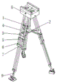
FIG. 1 is a schematic structural view of the present invention;
FIG. 2 is a schematic perspective view of the quick-mount mechanism of the present invention;
FIG. 3 is a schematic view of the internal structure of the quick mounting mechanism of the present invention;
FIG. 4 is a schematic perspective view of the stabilizing and adjusting support mechanism of the present invention;
FIG. 5 is a schematic view of a partial cross-sectional structure of the stabilizing and adjusting support mechanism of the present invention.
Wherein: a supporting column-1, a connecting disc-2, a limit through plate-3, a first supporting rod-4, a first connecting ring sleeve-5, a second supporting rod-6, a second connecting ring sleeve-7, a quick mounting mechanism-8, a stable adjusting supporting mechanism-9, a base-81, a side baffle-82, an adjusting knob-83, a worm-84, a sliding block-85, a fixed polish rod-86 and a clamping plate-87, a spongy cushion-88, a rotating rod-89, a cam-810, a piston rod-811, an air pressure chamber-812, a spring-813, an air pressure sucker-814, a fixed rod-91, an adjusting ring sleeve-92, a clamping pull rod-93, an adjusting rod-94, a supporting plate-95, a hinge-96, a side expanding plate-97 and a return spring-98.
Detailed Description
The present invention will be described in detail with reference to fig. 1 to 5, and the technical solutions in the embodiments of the present invention will be clearly and completely described, and it is obvious that the described embodiments are only a part of the embodiments of the present invention, and not all embodiments. All other embodiments, which can be derived by a person skilled in the art from the embodiments given herein without making any creative effort, shall fall within the protection scope of the present invention.
The invention provides a novel tripod head camera mounting device through improvement, which comprises a support column 1 and a quick mounting mechanism 8, wherein the lower end of the support column 1 is fixedly provided with a connecting disc 2, the quick mounting mechanism 8 is fixedly mounted at the upper end of the support column 1, the quick mounting mechanism 8 comprises a base 81, a side baffle 82, an adjusting rotating button 83, a worm 84, a sliding block 85, a fixed polished rod 86, a clamping plate 87, a sponge pad 88, a rotating rod 89, a cam 810, a piston rod 811, a pneumatic chamber 812, a spring 813 and a pneumatic sucker 814, the bottom of the base 81 is fixedly mounted at the upper end of the support column 1, the side baffle 82 is fixedly mounted on the side surface of the upper end of the base 81, so that the side baffle 82 can protect two sides of a camera, the adjusting rotating button 83 is embedded on the side surface of the base 81, the adjusting rotating button 83 is fixed with the head, the fixed polish rod 86 is fixedly installed inside the base 81, the fixed polish rod 86 penetrates through the inside of the sliding block 85 in a clearance fit mode, the sliding block 85 can slide stably on the fixed polish rod 86, the upper end of the sliding block 85 is fixed with the lower end of the clamping plate 87, the clamping plate 87 is located on the upper surface of the base 81, the side surface of the clamping plate 87 is tightly attached to the sponge pad 88, the sponge pad 88 can protect the outer surface of the camera, the rotating rod 89 penetrates through the front end of the inside of the base 81 in a clearance fit mode, the tail end of the rotating rod 89 is fixed with the cam 810, the cam 810 is installed inside the base 81, the upper end of the cam 810 abuts against the lower end of the piston rod 811, the piston rod 811 is installed inside the air pressure chamber 812 in a clearance fit mode, the piston rod 811 can move inside the air pressure chamber 812 conveniently, the spring 813 is fixedly installed inside the air, and the air pressure suction cup 814 is arranged on the upper surface of the base 81, so that the effect of firmly sucking the bottom of the camera by the air pressure suction cup 814 is facilitated.
The outside 3 fixed mutually with spacing logical board of connection pad 2, 3 inside running through of spacing logical board has first bracing piece 4, first bracing piece 4 adopts clearance fit to run through inside first connecting ring cover 5, 4 lower extreme fixed mounting of first bracing piece are inside second connecting ring cover 7, 5 inside and 6 upper ends of second bracing piece of first connecting ring cover are fixed mutually, second bracing piece 6 adopts clearance fit to run through inside second connecting ring cover 7, the inside and firm adjustment supporting mechanism 9 upper ends of second connecting ring cover 7 are fixed mutually, 6 lower extreme fixed mounting of second bracing piece is inside firm adjustment supporting mechanism 9.
The stable adjusting and supporting mechanism 9 comprises a fixing rod 91, an adjusting ring sleeve 92, a clamping pull rod 93, an adjusting rod 94, a supporting plate 95, a hinge 96, a side display plate 97 and a reset spring 98, wherein the upper end of the fixing rod 91 is fixedly arranged inside a second connecting ring sleeve 7, the lower end of the fixing rod 91 is fixedly arranged inside the adjusting ring sleeve 92, the clamping pull rod 93 is penetrated inside the adjusting ring sleeve 92 in a clearance fit manner, the upper end of the adjusting rod 94 is penetrated inside the fixing rod 91 in a clearance fit manner, the inside of the adjusting rod 94 is abutted to the clamping pull rod 93, the adjusting rod 94 and the clamping pull rod 93 are convenient to adjust clamping, the lower end of the adjusting rod 94 is fixedly arranged with the supporting plate 95, the side surface of the supporting plate 95 is hinged to the side display plate 97 through the hinge 96, the side display plate 97 is convenient to expand on the side surface of the supporting plate 95, and the clamping pull rod 93, and the left end of the return spring 98 is fixed with the inner wall of the left side of the adjusting ring sleeve 92, so that the return spring 98 can automatically return the clamping pull rod 93.
The number of the worms 84 is two, and the tail ends of the two worms 84 are fixed and run in opposite directions, so that the two sliding blocks 85 are driven to move in opposite directions.
Splint 87 and foam-rubber cushion 88 are equipped with two altogether, all are the cuboid structure, do benefit to and play the effect of pressing from both sides tightly and protecting the camera both sides.
The pneumatic suction cups 814 are provided with two pneumatic suction cups, which are respectively arranged at the front end and the rear end of the upper surface of the base 81, so that the pneumatic suction cups 814 can firmly adsorb the front end and the rear end of the bottom of the camera.
Firm regulation supporting mechanism 9 is equipped with threely altogether, installs respectively at three second bracing piece 6 lower extremes, does benefit to and plays the effect of independently adjusting three second bracing piece 6 through firm regulation supporting mechanism 9.
Adjust pole 94 inside and be equipped with six recesses to the size of recess and the terminal size phase-match of screens pull rod 93 do benefit to and play screens pull rod 93 and adjust pole 94 and carry out the effect of screens.
The side panel 97 is equipped with two altogether, and the left and right sides through two hinges 96 and backup pad 95 is articulated mutually, does benefit to the effect that increases the lifting surface area of backup pad 95 both sides.
The clamping plate 87 is made of stainless steel and has the advantage of high strength.
The return spring 98 is made of alloy spring steel, and has the advantage of high corrosion resistance.
The invention provides a novel tripod head camera mounting device through improvement, and the working principle is as follows;
firstly, before use, the three first supporting rods 4 are firstly pulled apart, so that the mounting device is in a triangular supporting structure;
secondly, the two side display plates 97 are unfolded at the two sides of the supporting plate 95 through the hinging action of the hinge 96, the stress area of the supporting plate 95 is increased, then the three stable adjusting and supporting mechanisms 9 are independently adjusted according to the stable condition of the ground, the clamping pull rod 93 is separated from the adjusting rod 94 and the fixed rod 91 through pulling out the clamping pull rod 93, at the moment, the length of the adjusting rod 94 is adjusted until the three second supporting rods 6 are on the same horizontal line, the stable installation mechanism 8 at the upper end is ensured to be kept stable, then the clamping pull rod 93 is loosened, the clamping pull rod 93 is reset through the reset spring 98, the clamping pull rod 93 and the fixed rod 91 are fixed, and the installation device and the ground are more stable;
thirdly, the camera is installed on the base 81, the camera is preliminarily protected through the side baffles 82 on the two sides, then the two worms 84 rotate through rotating the adjusting rotating button 83, the two sliding blocks 85 are driven to reversely slide, at the moment, the clamping plates 87 and the sponge pads 88 clamp and fix the two sides of the camera, then the cam 810 rotates through rotating the rotating rod 89, at the moment, the piston rod 811 loses stress, the piston rod 811 moves in the air pressure chamber 812 through the elasticity of the spring 813, the air in the air pressure suction cup 814 is exhausted, the air pressure suction cup 814 firmly adsorbs the bottom of the camera, the installation and fixation effects are improved, and the installation process is more convenient;
fourthly, after the installation is finished, shooting can be carried out through the camera.
The invention provides a novel tripod head camera mounting device through improvement, two side display plates 97 are unfolded on two sides of a support plate 95 through the hinging action of a hinge 96, the stress area of the support plate 95 is increased, then three stable adjusting support mechanisms 9 are independently adjusted according to the stable condition of the ground, a clamping pull rod 93 is separated from an adjusting rod 94 and a fixed rod 91 through pulling out the clamping pull rod 93, at the moment, the length of the adjusting rod 94 is adjusted to be on the same horizontal line of three second support rods 6, the stable mounting mechanism 8 at the upper end is ensured to be stable, then the clamping pull rod 93 is loosened, the clamping pull rod 93 is reset through a reset spring 98 to fix the clamping pull rod 93 and the fixed rod 91, the mounting device and the ground are more stable, then, a camera is mounted on a base 81, and the camera is preliminarily protected through the side baffle plates 82 at two sides, make two worms 84 rotate through rotating adjusting knob 83 next, the end has driven two sliders 85 and has carried out reverse slip, splint 87 and foam-rubber cushion 88 press from both sides tight fixedly this moment to the camera both sides, make cam 810 rotate through rotating rotary rod 89 after that, at this moment, piston rod 811 loses the atress, elasticity through spring 813 makes piston rod 811 move inside atmospheric pressure chamber 812, discharge the inside air of atmospheric pressure sucking disc 814, make atmospheric pressure sucking disc 814 firmly adsorb the camera bottom, the fixed effect of installation has been improved, the installation is more convenient.
The basic principles and main features of the present invention and the advantages of the present invention have been shown and described, and the standard parts used in the present invention are all available on the market, the special-shaped parts can be customized according to the description and the accompanying drawings, the specific connection mode of each part adopts the conventional means of bolt and rivet, welding and the like mature in the prior art, the machinery, parts and equipment adopt the conventional type in the prior art, and the circuit connection adopts the conventional connection mode in the prior art, and the details are not described herein.
The previous description of the disclosed embodiments is provided to enable any person skilled in the art to make or use the present invention. Various modifications to these embodiments will be readily apparent to those skilled in the art, and the generic principles defined herein may be applied to other embodiments without departing from the spirit or scope of the invention. Thus, the present invention is not intended to be limited to the embodiments shown herein but is to be accorded the widest scope consistent with the principles and novel features disclosed herein.
Claims (9)
1. A novel tripod head camera mounting device comprises a support pillar (1), wherein a connecting disc (2) is fixedly mounted at the lower end of the support pillar (1);
the method is characterized in that: still include quick installation mechanism (8), quick installation mechanism (8) fixed mounting is in support column (1) upper end, quick installation mechanism (8) includes base (81), side shield (82), adjust knob (83), worm (84), slider (85), fixed polished rod (86), splint (87), foam-rubber cushion (88), bull stick (89), cam (810), piston rod (811), pneumatic chamber (812), spring (813) and pneumatic suction cup (814), base (81) bottom fixed mounting is in support column (1) upper end, base (81) upper end side fixed mounting has side shield (82), adjust knob (83) inlay in base (81) side, adjust knob (83) and worm (84) head end fixed mutually to worm (84) fixed mounting is inside base (81), worm (84) run through inside slider (85) and threaded connection, the fixed polished rod (86) is fixedly installed inside the base (81), the fixed polished rod (86) penetrates through the inside of the sliding block (85) in a clearance fit mode, the upper end of the sliding block (85) is fixed with the lower end of the clamping plate (87), the clamping plate (87) is located on the upper surface of the base (81), the side surface of the clamping plate (87) is tightly attached to the sponge pad (88), the rotating rod (89) penetrates through the front end of the inside of the base (81) in a clearance fit mode, the tail end of the rotating rod (89) is fixed with the cam (810), the cam (810) is installed inside the base (81), the upper end of the cam (810) is abutted to the lower end of the piston rod (811), the piston rod (811) is installed inside the air pressure chamber (812) in a clearance fit mode, the spring (813) is fixedly installed inside the air pressure chamber (812), and the lower end of the spring (813) is abutted to, the upper end of the air pressure chamber (812) is fixed with the lower end of an air pressure sucker (814), and the air pressure sucker (814) is arranged on the upper surface of the base (81).
2. The novel pan-tilt camera mounting device according to claim 1, wherein: connection pad (2) outside is fixed mutually with spacing logical board (3), spacing logical board (3) inside runs through there are first bracing piece (4), first bracing piece (4) adopt clearance fit to run through inside first connection ring cover (5), first bracing piece (4) lower extreme fixed mounting is inside second connection ring cover (7), first connection ring cover (5) inside is fixed mutually with second bracing piece (6) upper end, second bracing piece (6) adopt clearance fit to run through inside second connection ring cover (7), second connection ring cover (7) inside is fixed mutually with firm adjustment supporting mechanism (9) upper end, second bracing piece (6) lower extreme fixed mounting is inside firm adjustment supporting mechanism (9).
3. The novel pan-tilt camera mounting device according to claim 2, wherein: the stable adjusting and supporting mechanism (9) comprises a fixing rod (91), an adjusting ring sleeve (92), a clamping pull rod (93), an adjusting rod (94), a supporting plate (95), a hinge (96), a side expanding plate (97) and a reset spring (98), wherein the upper end of the fixing rod (91) is fixedly arranged inside a second connecting ring sleeve (7), the lower end of the fixing rod (91) is fixedly arranged inside the adjusting ring sleeve (92), the clamping pull rod (93) penetrates inside the adjusting ring sleeve (92) in a clearance fit manner, the upper end of the adjusting rod (94) penetrates inside the fixing rod (91) in a clearance fit manner, the inside of the adjusting rod (94) is abutted against the clamping pull rod (93), the supporting plate (95) is fixedly arranged at the lower end of the adjusting rod (94), the side surface of the supporting plate (95) is hinged with the side expanding plate (97) through the hinge (96), and the clamping pull rod (93) penetrates inside the reset spring (98), and the left end of the return spring (98) is fixed with the inner wall of the left side of the adjusting ring sleeve (92).
4. The novel pan-tilt camera mounting device according to claim 1, wherein: the number of the worms (84) is two, and the tail ends of the two worms (84) are fixed and run in opposite directions.
5. The novel pan-tilt camera mounting device according to claim 1, wherein: the clamping plates (87) and the spongy cushions (88) are two and are of cuboid structures.
6. The novel pan-tilt camera mounting device according to claim 1, wherein: the number of the air pressure suckers (814) is two, and the two air pressure suckers are respectively arranged at the front end and the rear end of the upper surface of the base (81).
7. The novel pan-tilt camera mounting device according to claim 2, wherein: the number of the stable adjusting and supporting mechanisms (9) is three, and the stable adjusting and supporting mechanisms are respectively arranged at the lower ends of the three second supporting rods (6).
8. A novel pan-tilt-zoom camera mounting device according to claim 3, wherein: six grooves are formed in the adjusting rod (94), and the size of each groove is matched with the size of the tail end of the clamping pull rod (93).
9. A novel pan-tilt-zoom camera mounting device according to claim 3, wherein: the side display plate (97) is provided with two side display plates which are hinged with the left side and the right side of the support plate (95) through two hinges (96).
Priority Applications (1)
| Application Number | Priority Date | Filing Date | Title |
|---|---|---|---|
| CN201911377698.8A CN111022858A (en) | 2019-12-27 | 2019-12-27 | Novel cloud platform camera installation device |
Applications Claiming Priority (1)
| Application Number | Priority Date | Filing Date | Title |
|---|---|---|---|
| CN201911377698.8A CN111022858A (en) | 2019-12-27 | 2019-12-27 | Novel cloud platform camera installation device |
Publications (1)
| Publication Number | Publication Date |
|---|---|
| CN111022858A true CN111022858A (en) | 2020-04-17 |
Family
ID=70194473
Family Applications (1)
| Application Number | Title | Priority Date | Filing Date |
|---|---|---|---|
| CN201911377698.8A Pending CN111022858A (en) | 2019-12-27 | 2019-12-27 | Novel cloud platform camera installation device |
Country Status (1)
| Country | Link |
|---|---|
| CN (1) | CN111022858A (en) |
Cited By (3)
| Publication number | Priority date | Publication date | Assignee | Title |
|---|---|---|---|---|
| CN111895181A (en) * | 2020-08-13 | 2020-11-06 | 徐静刚 | Circular pipe gallery supporting and hanging frame |
| CN112197115A (en) * | 2020-10-10 | 2021-01-08 | 如皋市华灿置业有限公司 | Supporting device for building engineering detection |
| CN113339651A (en) * | 2021-06-21 | 2021-09-03 | 唐山师范学院 | Digital media display projection device convenient for adjusting inclination angle |
Citations (22)
| Publication number | Priority date | Publication date | Assignee | Title |
|---|---|---|---|---|
| US1517825A (en) * | 1923-06-21 | 1924-12-02 | Bruneau Eugene | Tripod |
| FR858713A (en) * | 1939-04-29 | 1940-12-02 | Tripod for cinematographic cameras | |
| JPS60208698A (en) * | 1984-03-07 | 1985-10-21 | キユルビ・ウント・ニツゲロ− | Conveyor for tripod |
| DE3805262A1 (en) * | 1988-02-19 | 1989-08-31 | Kuerbi & Niggeloh | Stand |
| JPH0336599U (en) * | 1989-08-21 | 1991-04-09 | ||
| DE9108498U1 (en) * | 1991-07-10 | 1991-10-17 | Sachtler Ag - Kommunikationstechnik, 8046 Garching, De | |
| CN1527920A (en) * | 2001-07-17 | 2004-09-08 | ��ŵ�йɷݹ�˾ | A stabiliser with telescopic rods for tripods and the like |
| CN101377261A (en) * | 2008-09-18 | 2009-03-04 | 陆伟明 | Three-segment integral telescopic tripod and locking mode |
| CN101382231A (en) * | 2007-09-07 | 2009-03-11 | 照相机动力有限责任公司 | Spider for a stand and set containing the spider and a tripod stand |
| CN202791187U (en) * | 2012-07-31 | 2013-03-13 | 刘雁春 | Cartridge clip type measuring tripod |
| CN103851321A (en) * | 2014-03-20 | 2014-06-11 | 桂林长海发展有限责任公司 | Ultralight high-strength tripod |
| CN203809990U (en) * | 2014-03-26 | 2014-09-03 | 东莞恒群塑胶有限公司 | Electronic device support frame |
| CN204411248U (en) * | 2015-01-08 | 2015-06-24 | 青岛市中心医院 | A kind of emergency treatment device for resuscitating heart and pulmones |
| CN105805510A (en) * | 2016-05-06 | 2016-07-27 | 王玉振 | Surveying and mapping instrument tripod |
| CN205640136U (en) * | 2016-05-06 | 2016-10-12 | 王玉振 | Surveying instrument tripod |
| CN108012057A (en) * | 2017-11-29 | 2018-05-08 | 滁州市华晨软件科技有限公司 | A kind of dining room monitoring system based on Computer Network Project |
| CN207684788U (en) * | 2017-11-01 | 2018-08-03 | 中国石油天然气股份有限公司 | Chain block frame |
| US20180274717A1 (en) * | 2017-03-24 | 2018-09-27 | Oberwerk Corporation | Leg For An Apparatus For Supporting An Object |
| CN108769582A (en) * | 2018-05-24 | 2018-11-06 | 深圳市律远汇智科技有限公司 | A kind of intelligent monitoring of install convenient |
| CN108825966A (en) * | 2018-06-21 | 2018-11-16 | 郑州艾莫弗信息技术有限公司 | A kind of computer research and development display/panel bracket for facilitating adjusting |
| CN109443410A (en) * | 2018-11-30 | 2019-03-08 | 中国人民解放军火箭军工程大学 | A kind of big stroke automatic leveling signal receiver tripod deployment system and implementation method |
| CN110073871A (en) * | 2019-05-30 | 2019-08-02 | 西安微电子技术研究所 | A kind of negative-pressure adsorption formation control mechanism and the sack bag mouth opener using the mechanism |
-
2019
- 2019-12-27 CN CN201911377698.8A patent/CN111022858A/en active Pending
Patent Citations (22)
| Publication number | Priority date | Publication date | Assignee | Title |
|---|---|---|---|---|
| US1517825A (en) * | 1923-06-21 | 1924-12-02 | Bruneau Eugene | Tripod |
| FR858713A (en) * | 1939-04-29 | 1940-12-02 | Tripod for cinematographic cameras | |
| JPS60208698A (en) * | 1984-03-07 | 1985-10-21 | キユルビ・ウント・ニツゲロ− | Conveyor for tripod |
| DE3805262A1 (en) * | 1988-02-19 | 1989-08-31 | Kuerbi & Niggeloh | Stand |
| JPH0336599U (en) * | 1989-08-21 | 1991-04-09 | ||
| DE9108498U1 (en) * | 1991-07-10 | 1991-10-17 | Sachtler Ag - Kommunikationstechnik, 8046 Garching, De | |
| CN1527920A (en) * | 2001-07-17 | 2004-09-08 | ��ŵ�йɷݹ�˾ | A stabiliser with telescopic rods for tripods and the like |
| CN101382231A (en) * | 2007-09-07 | 2009-03-11 | 照相机动力有限责任公司 | Spider for a stand and set containing the spider and a tripod stand |
| CN101377261A (en) * | 2008-09-18 | 2009-03-04 | 陆伟明 | Three-segment integral telescopic tripod and locking mode |
| CN202791187U (en) * | 2012-07-31 | 2013-03-13 | 刘雁春 | Cartridge clip type measuring tripod |
| CN103851321A (en) * | 2014-03-20 | 2014-06-11 | 桂林长海发展有限责任公司 | Ultralight high-strength tripod |
| CN203809990U (en) * | 2014-03-26 | 2014-09-03 | 东莞恒群塑胶有限公司 | Electronic device support frame |
| CN204411248U (en) * | 2015-01-08 | 2015-06-24 | 青岛市中心医院 | A kind of emergency treatment device for resuscitating heart and pulmones |
| CN105805510A (en) * | 2016-05-06 | 2016-07-27 | 王玉振 | Surveying and mapping instrument tripod |
| CN205640136U (en) * | 2016-05-06 | 2016-10-12 | 王玉振 | Surveying instrument tripod |
| US20180274717A1 (en) * | 2017-03-24 | 2018-09-27 | Oberwerk Corporation | Leg For An Apparatus For Supporting An Object |
| CN207684788U (en) * | 2017-11-01 | 2018-08-03 | 中国石油天然气股份有限公司 | Chain block frame |
| CN108012057A (en) * | 2017-11-29 | 2018-05-08 | 滁州市华晨软件科技有限公司 | A kind of dining room monitoring system based on Computer Network Project |
| CN108769582A (en) * | 2018-05-24 | 2018-11-06 | 深圳市律远汇智科技有限公司 | A kind of intelligent monitoring of install convenient |
| CN108825966A (en) * | 2018-06-21 | 2018-11-16 | 郑州艾莫弗信息技术有限公司 | A kind of computer research and development display/panel bracket for facilitating adjusting |
| CN109443410A (en) * | 2018-11-30 | 2019-03-08 | 中国人民解放军火箭军工程大学 | A kind of big stroke automatic leveling signal receiver tripod deployment system and implementation method |
| CN110073871A (en) * | 2019-05-30 | 2019-08-02 | 西安微电子技术研究所 | A kind of negative-pressure adsorption formation control mechanism and the sack bag mouth opener using the mechanism |
Cited By (4)
| Publication number | Priority date | Publication date | Assignee | Title |
|---|---|---|---|---|
| CN111895181A (en) * | 2020-08-13 | 2020-11-06 | 徐静刚 | Circular pipe gallery supporting and hanging frame |
| CN112197115A (en) * | 2020-10-10 | 2021-01-08 | 如皋市华灿置业有限公司 | Supporting device for building engineering detection |
| CN113339651A (en) * | 2021-06-21 | 2021-09-03 | 唐山师范学院 | Digital media display projection device convenient for adjusting inclination angle |
| CN113339651B (en) * | 2021-06-21 | 2022-05-03 | 唐山师范学院 | Digital media display projection device convenient for adjusting inclination angle |
Similar Documents
| Publication | Publication Date | Title |
|---|---|---|
| CN111022858A (en) | Novel cloud platform camera installation device | |
| CN211423781U (en) | Image equipment supporting device for outdoor performance | |
| CN216345084U (en) | Fixing and adjusting device of remote sensing image machine | |
| CN208474835U (en) | A kind of video-photographic balance bracket | |
| CN212251860U (en) | Remove indoor VR and shoot device | |
| US20240019766A1 (en) | Special effect screen and photo booth | |
| CN208997603U (en) | A kind of photographic goods support accessory for shooting | |
| CN214580175U (en) | Portable infrared thermal imaging camera | |
| CN208397630U (en) | With fixed bracket on a kind of video recorder | |
| CN214425564U (en) | Shoot alignment jig | |
| CN212107526U (en) | Tripod with impact protection for photography and video shooting | |
| CN209130450U (en) | A kind of adjustable jack post for video camera and mobile phone photographic | |
| CN209134516U (en) | A kind of candid photograph formula web camera | |
| CN213333434U (en) | Image measuring instrument convenient to use | |
| CN208572170U (en) | A kind of handset bracket | |
| CN219177270U (en) | Camera support | |
| CN111586274A (en) | Wearable self-timer | |
| CN213656165U (en) | Panoramic video shooting cloud platform | |
| CN215371773U (en) | Camera module of multi-angle formula | |
| CN220817210U (en) | Security protection camera installs and uses fixed bolster | |
| CN217216739U (en) | Cloud platform that has infrared thermal imaging function convenient to carry | |
| CN220416704U (en) | Distance-adjustable camera for computer | |
| CN220102671U (en) | High-end cradle head of digital camera | |
| CN220775431U (en) | Multi-interface power supply equipment | |
| CN212231544U (en) | Take cell-phone to press from both sides fast-assembling plate structure of function and can switch between mode of clapping anyhow fast |
Legal Events
| Date | Code | Title | Description |
|---|---|---|---|
| PB01 | Publication | ||
| PB01 | Publication | ||
| SE01 | Entry into force of request for substantive examination | ||
| SE01 | Entry into force of request for substantive examination | ||
| RJ01 | Rejection of invention patent application after publication | ||
| RJ01 | Rejection of invention patent application after publication |
Application publication date: 20200417 |