CN111022695B - High-temperature graphite sealing titanium alloy ball valve - Google Patents
High-temperature graphite sealing titanium alloy ball valve Download PDFInfo
- Publication number
- CN111022695B CN111022695B CN202010015462.6A CN202010015462A CN111022695B CN 111022695 B CN111022695 B CN 111022695B CN 202010015462 A CN202010015462 A CN 202010015462A CN 111022695 B CN111022695 B CN 111022695B
- Authority
- CN
- China
- Prior art keywords
- valve
- graphite
- valve seat
- seat
- ball
- Prior art date
- Legal status (The legal status is an assumption and is not a legal conclusion. Google has not performed a legal analysis and makes no representation as to the accuracy of the status listed.)
- Active
Links
Images


Classifications
-
- F—MECHANICAL ENGINEERING; LIGHTING; HEATING; WEAPONS; BLASTING
- F16—ENGINEERING ELEMENTS AND UNITS; GENERAL MEASURES FOR PRODUCING AND MAINTAINING EFFECTIVE FUNCTIONING OF MACHINES OR INSTALLATIONS; THERMAL INSULATION IN GENERAL
- F16K—VALVES; TAPS; COCKS; ACTUATING-FLOATS; DEVICES FOR VENTING OR AERATING
- F16K5/00—Plug valves; Taps or cocks comprising only cut-off apparatus having at least one of the sealing faces shaped as a more or less complete surface of a solid of revolution, the opening and closing movement being predominantly rotary
- F16K5/06—Plug valves; Taps or cocks comprising only cut-off apparatus having at least one of the sealing faces shaped as a more or less complete surface of a solid of revolution, the opening and closing movement being predominantly rotary with plugs having spherical surfaces; Packings therefor
-
- F—MECHANICAL ENGINEERING; LIGHTING; HEATING; WEAPONS; BLASTING
- F16—ENGINEERING ELEMENTS AND UNITS; GENERAL MEASURES FOR PRODUCING AND MAINTAINING EFFECTIVE FUNCTIONING OF MACHINES OR INSTALLATIONS; THERMAL INSULATION IN GENERAL
- F16K—VALVES; TAPS; COCKS; ACTUATING-FLOATS; DEVICES FOR VENTING OR AERATING
- F16K27/00—Construction of housing; Use of materials therefor
- F16K27/06—Construction of housing; Use of materials therefor of taps or cocks
- F16K27/067—Construction of housing; Use of materials therefor of taps or cocks with spherical plugs
-
- F—MECHANICAL ENGINEERING; LIGHTING; HEATING; WEAPONS; BLASTING
- F16—ENGINEERING ELEMENTS AND UNITS; GENERAL MEASURES FOR PRODUCING AND MAINTAINING EFFECTIVE FUNCTIONING OF MACHINES OR INSTALLATIONS; THERMAL INSULATION IN GENERAL
- F16K—VALVES; TAPS; COCKS; ACTUATING-FLOATS; DEVICES FOR VENTING OR AERATING
- F16K5/00—Plug valves; Taps or cocks comprising only cut-off apparatus having at least one of the sealing faces shaped as a more or less complete surface of a solid of revolution, the opening and closing movement being predominantly rotary
- F16K5/06—Plug valves; Taps or cocks comprising only cut-off apparatus having at least one of the sealing faces shaped as a more or less complete surface of a solid of revolution, the opening and closing movement being predominantly rotary with plugs having spherical surfaces; Packings therefor
- F16K5/0663—Packings
- F16K5/0694—Spindle sealings
-
- F—MECHANICAL ENGINEERING; LIGHTING; HEATING; WEAPONS; BLASTING
- F16—ENGINEERING ELEMENTS AND UNITS; GENERAL MEASURES FOR PRODUCING AND MAINTAINING EFFECTIVE FUNCTIONING OF MACHINES OR INSTALLATIONS; THERMAL INSULATION IN GENERAL
- F16K—VALVES; TAPS; COCKS; ACTUATING-FLOATS; DEVICES FOR VENTING OR AERATING
- F16K5/00—Plug valves; Taps or cocks comprising only cut-off apparatus having at least one of the sealing faces shaped as a more or less complete surface of a solid of revolution, the opening and closing movement being predominantly rotary
- F16K5/08—Details
- F16K5/14—Special arrangements for separating the sealing faces or for pressing them together
- F16K5/20—Special arrangements for separating the sealing faces or for pressing them together for plugs with spherical surfaces
- F16K5/201—Special arrangements for separating the sealing faces or for pressing them together for plugs with spherical surfaces with the housing or parts of the housing mechanically pressing the seal against the plug
Landscapes
- Engineering & Computer Science (AREA)
- General Engineering & Computer Science (AREA)
- Mechanical Engineering (AREA)
- Taps Or Cocks (AREA)
Abstract
The invention relates to a high-temperature graphite sealing titanium alloy ball valve which comprises a valve body, a ball body, a left valve seat assembly, a right valve seat assembly, a pin shaft, a valve rod, an anti-blowing ring, a graphite pad, a PTFE (polytetrafluoroethylene) pad, graphite packing, a packing gland, a valve body sealing pad, a limiting block, a handle or a driving device and the like. The graphite valve seat sealing mode combining the floating ball and the pre-tightening valve seat structure is adopted, the self-lubricating effect is achieved, the opening and closing torque of the ball valve is effectively reduced, and the reliable sealing and long-life operation of the ball valve under the high-temperature corrosion-resistant working condition are guaranteed.
Description
Technical Field
The invention relates to a graphite-sealed titanium alloy ball valve used under a high-temperature working condition, in particular to a one-way-flowing graphite-sealed ball valve which is suitable for the high-temperature working condition, takes a flowing medium as gas and does not contain particle impurities.
Background
The main function of a ball valve is to cut off or open a fluid passage in a pipe, typically a closed circuit valve. Ball valves used in the existing industry are classified into top mount type, bottom mount type, side mount type, and tilt mount type according to the ball mounting manner. No matter how the installation mode of the ball body is, the structural style of the ball valve is only two types of fixed ball valve and floating ball valve, the ball body of the floating ball valve is freely supported on the valve seat, and the ball body generates displacement in the fluid flow direction under the action of fluid pressure, so that the sealing surface of the valve seat is tightly contacted with the ball body after the valve, and single-side sealing is formed; the ball body of the fixed ball valve is provided with an upper rotating shaft and a lower rotating shaft and is fixed in a bearing of the ball body, the position of the ball body is fixed, the valve seat is floating, and the valve seat is in close contact with the ball body under the action of spring force and medium force to realize sealing.
The ball valves commonly used in China at present are classified from sealing types: mainly comprises a hard seal ball valve and a soft seal ball valve. The hard seal ball valve has the characteristics of small flow resistance, high temperature resistance, wear resistance, high requirements on processing and manufacturing processes, poor self-lubricating effect and the like, and is mainly applied to large-caliber high-temperature working conditions; the soft seal ball valve mainly has the characteristics of small flow resistance, easy abrasion, good sealing performance, poor temperature adaptability and the like, and is mainly applied to the working condition of small caliber, low temperature and pure medium.
Disclosure of Invention
The invention aims to provide a titanium alloy ball valve which is small in flow resistance, corrosion-resistant, high-temperature-resistant, small in opening and closing moment and reliable in sealing, so as to meet the requirements of high-temperature and corrosion-resistant working environments.
In order to achieve the purpose, the invention adopts the technical scheme that: a high-temperature graphite sealing titanium alloy ball valve comprises a valve body, a valve seat, a valve rod and a ball body, wherein the valve body is formed by combining a left valve body and a right valve body; the left valve body is connected with the upstream end of a pipeline where the ball valve is located, a through hole communicated with the valve cavity is formed in the upper portion of the left valve body so as to install the valve rod, a shoulder protruding in the radial direction is formed in the inner wall of the through hole, a stuffing box used for placing graphite stuffing is defined by the valve rod, the inner wall of the through hole and the upper plane of the shoulder, the stuffing box is sealed by a stuffing gland, and the graphite stuffing is compressed; the lower plane of the shoulder can support an anti-blowing ring arranged at the lower part of the valve rod to prevent the valve rod from loosening, and a PTFE (polytetrafluoroethylene) pad and a graphite pad are arranged between the shoulder and the anti-blowing ring; graphite sealing structures are arranged between the valve seat and the valve body and between the valve seat and the ball body, and a pre-tightening assembly is used for providing sealing pre-tightening force for the graphite sealing structures between the valve seat and the right valve body.
The valve rod is provided with a limiting block, the lower end face of the limiting block is tightly attached to the packing gland, and the upper end face of the limiting block realizes axial positioning through a retaining ring additionally arranged on the valve rod; the limiting washer is additionally arranged between the packing gland pre-tightening bolt and the packing gland, and the valve rod can be tightly attached to the side face of the limiting washer in an opening or closing state, so that the opening and closing position of the valve rod is limited.
The valve seat comprises an upstream valve seat and a downstream valve seat, the ball body is positioned between the upstream valve seat and the downstream valve seat, metal-graphite sealing structures are respectively adopted between the ball body and the upstream valve seat and between the ball body and the downstream valve seat, and each metal-graphite sealing structure comprises a metal ring groove arranged on the upstream valve seat or the downstream valve seat and a graphite sealing seat embedded in the metal ring groove; adopt graphite seal ring I to seal between upper reaches disk seat and the left valve body, adopt graphite seal ring II to seal between lower reaches disk seat and the right valve body to utilize the pretension subassembly to provide sealed pretightning force for graphite seal ring II between lower reaches disk seat and the right valve body.
An upstream valve seat metal ring is arranged on the upstream valve seat, a metal ring groove is processed on one surface of the upstream valve seat metal ring opposite to the ball body, the upstream valve seat metal ring is matched with the left valve body through a step structure, and a graphite sealing ring I is arranged; the downstream valve seat is provided with a downstream valve seat metal ring, a metal ring groove is machined on the surface, opposite to the ball body, of the downstream valve seat metal ring, the downstream valve seat metal ring is matched with the right valve body through a step structure, and a graphite sealing ring II and a pre-tightening assembly are arranged.
The pre-tightening assembly comprises a spring and a valve seat backing ring, and the valve seat backing ring is arranged between the spring and the graphite sealing ring II.
The spring is a disc spring.
The bottom of metal annular is equipped with waterline structure to guarantee the graphite seal seat and the metal ring between sealed after embedding the metal annular.
The valve body, the upstream valve seat metal ring and the downstream valve seat metal ring are all made of titanium alloy.
The bottom of the valve rod is provided with a shaft hole and a pin shaft, and the part of the pin shaft, which is exposed out of the shaft hole, is provided with an anti-blowing ring.
And a mounting groove is formed between the left valve body and the right valve body, so that a graphite winding pad and a valve body sealing pad which are used for preventing the medium from leaking outwards can be mounted.
By using the technical scheme, the following effects can be achieved: 1. the internal and external leakage of the valve is effectively prevented in a high-temperature environment. 2. The moment of force among the effectual reduction ball valve switch process, the disk seat has self-lubricating effect. 3. The structure that adopts titanium alloy becket and imbed graphite seal seat has effectually improved the operational reliability of valve under the corrosivity operating mode. 4. The anti-blowing ring structure is adopted, so that the length direction of the valve rod is not limited, and the valve rod is prevented from being blown out after being pressed. 5. The structure form of sealing the floating ball valve and the spring pre-tightening valve seat is adopted, so that reliable sealing between the valve seat and the ball body is effectively guaranteed.
Drawings
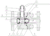
FIG. 1 is a schematic structural view of the present invention;
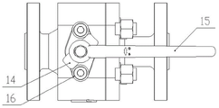
FIG. 2 is a top view of the present invention;
FIG. 3 is an enlarged view taken at I in FIG. 1;
FIG. 4 is an enlarged view taken at II in FIG. 1;
FIG. 5 is a schematic view of the valve stem of the present invention;
the labels in the figure are: 1. a right valve body; 2. a left valve body; 3. a sphere; 4. an upstream valve seat; 5. a downstream valve seat; 6. a valve stem; 7. a graphite pad; 8. a PTFE pad; 9. graphite filler; 10. a packing gland; 11. a retainer ring; 12. a graphite wound mat; 13. a valve body gasket; 14. a limiting block; 15. a handle; 16. a limiting washer;
400. an upstream valve seat metal ring; 401. a graphite sealing seat I; 402. a graphite sealing ring I;
500. an upstream valve seat metal ring; 501. a graphite seal seat II; 502. a disc spring; 503. a valve seat backing ring; 504. a graphite sealing ring II;
601. a pin shaft; 602. an anti-blow ring.
Detailed Description
The present invention will be described in further detail with reference to the following drawings and examples, but the invention is not limited thereto.
Referring to the attached drawings, the main parts of the high-temperature graphite sealing titanium alloy ball valve comprise a valve body, a ball body 3, an upstream valve seat 4, a downstream valve seat 5, a valve rod 6, a pin shaft 601, an anti-blowing ring 602, a graphite pad 7, a PTFE pad 8, graphite packing 9, a packing gland 10, a valve body sealing pad 13, a limiting block 14, a handle 15 or a driving device and the like.
Designing a valve body: the valve body is made of titanium alloy materials, adopts a split structure and consists of a left valve body and a right valve body which are in asymmetric structures, the left valve body 2 is communicated with the upstream end of a pipeline, and the right valve body 1 is communicated with the downstream end. The left valve body 2 and the right valve body 1 are matched and assembled and are all processed into a full-bore straight-through structure, the left valve body 2 and the right valve body 1 are combined to form a valve cavity, and a mounting groove for mounting the graphite winding pad 12 and the valve body sealing pad 13 is designed between the left valve body and the right valve body and used for preventing the medium from leaking outwards.
The upper part of the left valve body 2 is provided with a through hole communicated with the valve cavity so as to install the valve rod 6, the inner wall of the through hole is provided with a shoulder protruding in the radial direction, a stuffing box used for filling the graphite stuffing 9 is formed by the valve rod 6, the inner wall of the through hole and the upper plane of the shoulder in a surrounding mode, and a stuffing gland 10 is used for sealing the stuffing box and compressing the graphite stuffing 9.
Designing a valve seat and a sealing structure: the valve seat comprises an upstream valve seat 4 and a downstream valve seat 5, the upstream valve seat 4 is installed in a matched mode with the left valve body 2, and the downstream valve seat 5 is installed in a matched mode with the right valve body 1. The ball 3 is positioned between the upstream valve seat 4 and the downstream valve seat 5, metal-graphite sealing structures are respectively adopted between the ball 3 and the upstream valve seat 4 and between the ball 3 and the downstream valve seat 5, and each metal-graphite sealing structure comprises a metal ring groove arranged on the upstream valve seat 4 or the downstream valve seat 5 and a graphite sealing seat I401 or a graphite sealing seat II 501 embedded in the metal ring groove; the valve body is characterized in that a graphite sealing ring I402 is used for sealing between the upstream valve seat 4 and the left valve body 2, a graphite sealing ring II 504 is used for sealing between the downstream valve seat 5 and the right valve body 1, and a pre-tightening assembly is used for providing sealing pre-tightening force for the graphite sealing ring II 504.
Fig. 3 shows the sealing structure between the upstream valve seat 4 and the ball 3, and between the upstream valve seat and the left valve body 2. As shown in fig. 3, the upstream valve seat 4 is in an assembly form, and includes an upstream valve seat metal ring 400 and the graphite sealing seat i 401, the metal ring groove is processed on the upstream valve seat metal ring 400 on the side opposite to the ball body 3, a plurality of rows of sawtooth-shaped tooth grooves (not shown in the figure) are formed at the bottom of the metal ring groove to form a waterline structure, the graphite sealing seat i 401 is embedded into the metal ring groove while being embedded into the metal ring groove, so as to increase the bonding strength between the graphite sealing seat i 401 and the upstream valve seat metal ring 400, and further improve the sealing effect of the graphite sealing seat i 401 on the ball body 3 and the upstream valve seat 4. After the graphite sealing seat I401 is embedded, the reliable sealing of the upstream valve seat 4 and the ball 3 is ensured through contact extrusion with the ball 3.
For the seal between the upstream valve seat 4 and the left valve body 2: the upstream valve seat metal ring 400 is matched with the left valve body 2 through a step structure, and a graphite sealing ring I402 is arranged.
Fig. 4 shows the sealing arrangement between the downstream valve seat 5 and the ball 3 and between the right valve body 1. As shown in fig. 4, the downstream valve seat 5 is in an assembly form, and includes a downstream valve seat metal ring 500 and the graphite sealing seat ii 501, the metal ring groove is processed on the downstream valve seat metal ring 500 at the side opposite to the ball 3, a plurality of rows of sawtooth-shaped tooth grooves (not shown in the figure) are formed at the bottom of the metal ring groove to form a waterline structure, and the graphite sealing seat ii 501 is embedded into the tooth grooves while being embedded into the metal ring groove, so as to increase the bonding strength between the graphite sealing seat ii 501 and the downstream valve seat metal ring 500, and further improve the sealing effect of the graphite sealing seat ii 501 on the ball 3 and the downstream valve seat 5.
For the sealing between the downstream valve seat 5 and the right valve body 1: the downstream valve seat metal ring 500 is matched with the right valve body 1 through a step structure, and a graphite sealing ring II 504 and a pre-tightening assembly are arranged.
The pre-tightening assembly comprises a spring and a valve seat backing ring 503, the valve seat backing ring 503 is arranged between the spring and the graphite sealing ring II 504, and the spring is a disc spring 502.
The valve body, the upstream seat metal ring 400 and the downstream seat metal ring 500 are all made of titanium alloy.
The structural design of the valve rod: the valve rod 6 adopts an upper mounting type structure form, the prior side mounting mode is broken, and a shoulder is not machined. As shown in fig. 5, in order to ensure that the stem 6 is not blown out when pressurized, a shaft hole is formed in the bottom of the stem 6, a pin 601 is fitted, and a blow-out preventing ring 602 is provided in a portion of the pin 601 where the shaft hole is exposed. A PTFE pad 8 and a graphite pad 7 are also arranged between the shoulder of the inner wall of the through hole of the valve rod 6 arranged on the left valve body 2 and the blow-proof ring 602.
A limiting block 14 is arranged on the valve rod 6, the lower end face of the limiting block 14 is tightly attached to the packing gland 10, and the upper end face of the limiting block is axially positioned through a check ring 11 additionally arranged on the valve rod 6; a limit gasket 16 is additionally arranged between the packing gland pre-tightening bolt and the packing gland 10, and the valve rod 6 can be tightly attached to the side faces of the limit gasket 16 and the limit block 14 in an opening or closing state, so that the opening and closing position of the valve rod 6 is limited.
The main principle of the structure of the invention is as follows:
when the ball 3 is in a closed state, the upstream medium generates pressure to press the upstream valve seat 4 to the ball 3, and the downstream valve seat 5 generates pretightening force under the action of the butterfly spring 502 to press the downstream valve seat 5 to the ball 3; the reliable sealing between the ball 3 and the valve seat is ensured under the combined action of the medium pressure and the pretightening force of the disc spring 502. Meanwhile, reliable sealing is formed due to the extrusion between the graphite sealing ring I402 and the upstream valve seat 4 and the extrusion between the graphite sealing ring II 504 and the downstream valve seat 5, so that the reliable sealing of the medium is ensured. Under the high-temperature working condition, the high-temperature resistance of the graphite material ensures the reliability of sealing.
When the sphere 3 is to be opened, the valve rod 6 needs to be rotated by external torque (the external torque can be provided by manual, electric, pneumatic and other driving modes), the rotation of the valve rod 6 can drive the sphere 3 to rotate, and the position between the limiting block 14 and the limiting gasket 16 is limited, so that the valve rod 6 and the sphere 3 can only rotate within the range of 90 degrees. When the sphere 3 is in a half-open state, a medium can fill the valve cavity, the valve rod 6 can be subjected to upward pressure under the pressure of the medium, and the valve rod 6 cannot be blown out due to the effects of the anti-blowing ring 602, the pin shaft 601 and the shoulder below the stuffing box; in-process is opened at the ball valve, spheroid 3 open the process can with graphite seal receptacle I401, graphite seal receptacle II 501 between produce the friction, adopt the effectual moment of torsion that reduces the friction production between spheroid 3 and graphite seal receptacle I401, graphite seal receptacle II 501 of graphite material. And a PTFE (polytetrafluoroethylene) pad 8 and a graphite pad 7 are arranged between the blow-proof ring 602 and the left valve body 2, so that the input torque required for opening the valve is effectively reduced.
The method comprises the following specific implementation steps: the invention is applied to a gas transmission pipeline system under the working conditions of 205 ℃ high temperature and corrosion resistance of a certain chemical project. Aiming at 1/2' 300Lb titanium alloy graphite ball valve, in order to ensure reliable sealing under high temperature working condition, the ball valve is designed into a valve seat sealing structure form with a left and right non-complete symmetrical structure according to the technical scheme of the invention. In order to ensure that the titanium alloy graphite ball valve meets the index requirement of zero leakage, a special grinding tool needs to be adopted to grind the ball after the ball is machined, the roundness and the surface roughness of the ball are ensured to meet the sealing requirement, meanwhile, after the ball is ground, the graphite seal seat and the ball are matched and ground, the matched grinding comprises two processes of coarse grinding and fine grinding, and reliable sealing is effectively ensured through the matched grinding. The packing, the sealing gasket and the graphite sealing seat are made of graphite materials, so that the reliable sealing of the ball valve under the working conditions of high temperature and corrosion is effectively guaranteed, the opening and closing torque of the ball valve is reduced, and the wear resistance and the corrosion resistance of a sealing pair are improved. In order to ensure that the valve rod cannot be blown out by a medium to cause casualties in the working process, the valve rod structure with the combination of the blowing-proof ring and the pin shaft is designed; simultaneously, design the stopper, when the valve rod rotates 90 and carries out the on-off operation, because the effect of stopper, the effectual spheroid rotation range restriction of having guaranteed is between 0~90, ensures that disk seat and spheroidal joining in marriage and grinds the face and fully laminates, reliably seals.
The above embodiments are only intended to illustrate the technical solution of the present invention and not to limit the same, and it should be understood by those of ordinary skill in the art that the specific embodiments of the present invention can be modified or substituted with equivalents with reference to the above embodiments, and any modifications or equivalents without departing from the spirit and scope of the present invention are within the scope of the claims to be appended.
Claims (7)
1. A high-temperature graphite sealing titanium alloy ball valve comprises a valve body, a valve seat, a valve rod (6) and a ball body (3), wherein the valve body is formed by combining a left valve body (2) and a right valve body (1), the valve seat and the ball body (3) are arranged in a valve cavity enclosed by the left valve body (2) and the right valve body (1), and the valve rod (6) extends into the valve cavity to drive the ball body (3) to rotate; the method is characterized in that: the left valve body (2) and the right valve body (1) are of asymmetric structures, the valve cavity is positioned in the left valve body (2), and a mounting groove is formed between the left valve body (2) and the right valve body (1) to mount a graphite winding pad (12) and a valve body sealing pad (13) for preventing media from leaking outwards; the left valve body (2) is connected with the upstream end of a pipeline where the ball valve is located, a through hole communicated with the valve cavity is formed in the upper portion of the left valve body (2) to install the valve rod (6), a shoulder protruding in the radial direction is arranged on the inner wall of the through hole, a stuffing box used for placing graphite stuffing (9) is defined by the valve rod (6), the inner wall of the through hole and the upper plane of the shoulder, the stuffing box is sealed by a stuffing gland (10), and the graphite stuffing (9) is compressed; the lower plane of the shoulder can prop against an anti-blowing ring (602) arranged at the lower part of the valve rod (6) to prevent the valve rod (6) from loosening, and a PTFE (polytetrafluoroethylene) pad (8) and a graphite pad (7) are also arranged between the shoulder and the anti-blowing ring (602); graphite sealing structures are arranged between the valve seat and the valve body and between the valve seat and the ball body (3), and a pre-tightening component is used for providing sealing pre-tightening force for the graphite sealing structures between the valve seat and the right valve body (1);
the valve seat comprises an upstream valve seat (4) and a downstream valve seat (5), the ball body (3) is positioned between the upstream valve seat (4) and the downstream valve seat (5), metal-graphite sealing structures are respectively adopted between the ball body (3) and the upstream valve seat (4) and between the ball body (3) and the downstream valve seat (5), and each metal-graphite sealing structure comprises a metal ring groove arranged on the upstream valve seat (4) or the downstream valve seat (5) and a graphite sealing seat embedded in the metal ring groove; the upstream valve seat (4) and the left valve body (2) are sealed by a graphite sealing ring I (402), the downstream valve seat (5) and the right valve body (1) are sealed by a graphite sealing ring II (504), and a pre-tightening component is used for providing sealing pre-tightening force for the graphite sealing ring II (504) between the downstream valve seat (5) and the right valve body (1);
an upstream valve seat metal ring (400) is arranged on the upstream valve seat (4), the metal ring groove is processed on the surface, opposite to the ball body (3), of the upstream valve seat metal ring (400), the upstream valve seat metal ring (400) is matched with the left valve body (2) through a step structure, and a graphite sealing ring I (402) is arranged; be equipped with low reaches disk seat becket (500) on low reaches disk seat (5), the one side relative with spheroid (3) is processed on low reaches disk seat becket (500) the metal ring groove, through the stair structure cooperation between low reaches disk seat becket (500) and right valve body (1) to set up graphite sealing ring II (504) and pretension subassembly.
2. The high-temperature graphite-sealed titanium alloy ball valve according to claim 1, characterized in that: a limiting block (14) is mounted on the valve rod (6), the lower end face of the limiting block (14) is tightly attached to the packing gland (10), and the upper end face of the limiting block (14) is axially positioned through a check ring (11) additionally mounted on the valve rod (6); a limit gasket (16) is additionally arranged between the packing gland pre-tightening bolt and the packing gland (10), and the valve rod (6) can be tightly attached to the side faces of the limit block (14) and the limit gasket (16) in an opening or closing state, so that the switch position of the valve rod (6) is limited.
3. The high-temperature graphite-sealed titanium alloy ball valve according to claim 1, characterized in that: the pre-tightening assembly comprises a spring and a valve seat backing ring (503), and the valve seat backing ring (503) is arranged between the spring and the graphite sealing ring II (504).
4. The high-temperature graphite-sealed titanium alloy ball valve according to claim 3, wherein: the spring is a disc spring (502).
5. The high-temperature graphite-sealed titanium alloy ball valve according to claim 1, characterized in that: the bottom of metal annular is equipped with waterline structure to guarantee the graphite seal seat and the metal ring between sealed after embedding the metal annular.
6. The high-temperature graphite-sealed titanium alloy ball valve according to claim 1, characterized in that: the valve body, the upstream valve seat metal ring (400) and the downstream valve seat metal ring (400) are all made of titanium alloy.
7. The high-temperature graphite-sealed titanium alloy ball valve according to claim 1, characterized in that: the bottom of the valve rod (6) is provided with a shaft hole and is provided with a pin shaft (601), and the part of the pin shaft (601) exposed out of the shaft hole is provided with an anti-blowing ring (602).
Priority Applications (1)
| Application Number | Priority Date | Filing Date | Title |
|---|---|---|---|
| CN202010015462.6A CN111022695B (en) | 2020-01-07 | 2020-01-07 | High-temperature graphite sealing titanium alloy ball valve |
Applications Claiming Priority (1)
| Application Number | Priority Date | Filing Date | Title |
|---|---|---|---|
| CN202010015462.6A CN111022695B (en) | 2020-01-07 | 2020-01-07 | High-temperature graphite sealing titanium alloy ball valve |
Publications (2)
| Publication Number | Publication Date |
|---|---|
| CN111022695A CN111022695A (en) | 2020-04-17 |
| CN111022695B true CN111022695B (en) | 2022-03-08 |
Family
ID=70198732
Family Applications (1)
| Application Number | Title | Priority Date | Filing Date |
|---|---|---|---|
| CN202010015462.6A Active CN111022695B (en) | 2020-01-07 | 2020-01-07 | High-temperature graphite sealing titanium alloy ball valve |
Country Status (1)
| Country | Link |
|---|---|
| CN (1) | CN111022695B (en) |
Families Citing this family (5)
| Publication number | Priority date | Publication date | Assignee | Title |
|---|---|---|---|---|
| CN112081788B (en) * | 2020-08-28 | 2022-06-03 | 西安航空职业技术学院 | Aviation hydraulic valve |
| CN112253791A (en) * | 2020-10-29 | 2021-01-22 | 上海沪东造船阀门有限公司 | Double-sealing ball valve with compensation valve seat |
| CN112303280A (en) * | 2020-12-18 | 2021-02-02 | 安徽齐力不锈钢制品有限公司 | PTFE ball valve with precise structure |
| CN113324064A (en) * | 2021-06-03 | 2021-08-31 | 苏州澎瀚阀门有限公司 | Low-temperature crystallization valve |
| CN114001172A (en) * | 2021-11-17 | 2022-02-01 | 西诺威阀门控制(苏州)有限公司 | High-temperature metal sealing ball valve |
Citations (8)
| Publication number | Priority date | Publication date | Assignee | Title |
|---|---|---|---|---|
| CN200958623Y (en) * | 2006-09-26 | 2007-10-10 | 武纪海 | Flow-controlled ball valve switch |
| CN101285532A (en) * | 2008-05-19 | 2008-10-15 | 浙江沃尔达铜业有限公司 | Multi-gear valve |
| CN201535368U (en) * | 2009-06-26 | 2010-07-28 | 上海耐莱斯·詹姆斯伯雷阀门有限公司 | Novel seal ceramic ball valve |
| CN202768925U (en) * | 2012-08-29 | 2013-03-06 | 江阴万讯自控设备有限公司 | Single-flow-direction floating ball metal hard sealing ball valve |
| CN205937945U (en) * | 2016-08-17 | 2017-02-08 | 超达阀门集团股份有限公司 | Two -way metal seal's of high temperature unsteady ball valve |
| CN208886022U (en) * | 2018-09-18 | 2019-05-21 | 江苏海纬集团有限公司 | A kind of wear-resisting anti-jamming ball valve |
| CN208935441U (en) * | 2018-08-07 | 2019-06-04 | 格业阀门有限公司 | The hard sealing and fixing type ball valve of high pressure |
| CN110043683A (en) * | 2018-01-16 | 2019-07-23 | 深圳市飞托克实业有限公司 | Valve |
Family Cites Families (1)
| Publication number | Priority date | Publication date | Assignee | Title |
|---|---|---|---|---|
| US6250604B1 (en) * | 1998-03-02 | 2001-06-26 | T & R Solutions, Inc. | Valve stem and method of manufacturing, improved stem packing |
-
2020
- 2020-01-07 CN CN202010015462.6A patent/CN111022695B/en active Active
Patent Citations (8)
| Publication number | Priority date | Publication date | Assignee | Title |
|---|---|---|---|---|
| CN200958623Y (en) * | 2006-09-26 | 2007-10-10 | 武纪海 | Flow-controlled ball valve switch |
| CN101285532A (en) * | 2008-05-19 | 2008-10-15 | 浙江沃尔达铜业有限公司 | Multi-gear valve |
| CN201535368U (en) * | 2009-06-26 | 2010-07-28 | 上海耐莱斯·詹姆斯伯雷阀门有限公司 | Novel seal ceramic ball valve |
| CN202768925U (en) * | 2012-08-29 | 2013-03-06 | 江阴万讯自控设备有限公司 | Single-flow-direction floating ball metal hard sealing ball valve |
| CN205937945U (en) * | 2016-08-17 | 2017-02-08 | 超达阀门集团股份有限公司 | Two -way metal seal's of high temperature unsteady ball valve |
| CN110043683A (en) * | 2018-01-16 | 2019-07-23 | 深圳市飞托克实业有限公司 | Valve |
| CN208935441U (en) * | 2018-08-07 | 2019-06-04 | 格业阀门有限公司 | The hard sealing and fixing type ball valve of high pressure |
| CN208886022U (en) * | 2018-09-18 | 2019-05-21 | 江苏海纬集团有限公司 | A kind of wear-resisting anti-jamming ball valve |
Also Published As
| Publication number | Publication date |
|---|---|
| CN111022695A (en) | 2020-04-17 |
Similar Documents
| Publication | Publication Date | Title |
|---|---|---|
| CN111022695B (en) | High-temperature graphite sealing titanium alloy ball valve | |
| CN201050598Y (en) | Mechanical seal | |
| CN201884690U (en) | Super-high pressure flat plate gate valve | |
| CN102094987A (en) | Ultrahigh pressure flat plate gate valve | |
| CN117432813A (en) | Spring type multi-stage throttling emptying valve | |
| US5205536A (en) | Top entry, trunnion-type ball valve | |
| CN213117571U (en) | Hard sealing fixed ball valve | |
| CN200940702Y (en) | Metal hard sealing ball valve | |
| CN211474940U (en) | Spherical bidirectional high-performance rotary valve | |
| CN205715756U (en) | A kind of novel anti-gray valve seat construction of Coal Chemical Industry ball valve | |
| CN210014024U (en) | Novel plate valve | |
| CN211649126U (en) | Welding ball valve that floats | |
| CN200946673Y (en) | Double-eccentric bi-directional metal seal butterfly valve | |
| CN203202254U (en) | Double-eccentric and bidirectional metallic seal butterfly valve | |
| CN201225413Y (en) | Ball valve | |
| CN108953621B (en) | Instrument stop valve | |
| CN219712401U (en) | Low-torque pressure self-sealing fixed ball valve | |
| CN221323368U (en) | Side-mounted bidirectional sealing C-type eccentric ball valve | |
| CN219588159U (en) | Hard seal fixed ball valve | |
| CN220870129U (en) | High wear-resisting lining ball valve | |
| CN214946438U (en) | High-frequency switch high-performance butterfly valve | |
| CN211779094U (en) | Integrated welded eccentric half-ball valve | |
| CN109854774A (en) | Three eccentricity seals c-type ball valve firmly | |
| CN116624611A (en) | Top-mounted valve and fluid delivery system | |
| CN110553056A (en) | Spherical bidirectional high-performance rotary valve |
Legal Events
| Date | Code | Title | Description |
|---|---|---|---|
| PB01 | Publication | ||
| PB01 | Publication | ||
| SE01 | Entry into force of request for substantive examination | ||
| SE01 | Entry into force of request for substantive examination | ||
| GR01 | Patent grant | ||
| GR01 | Patent grant |