CN111014817A - Aluminum bar sawing machine - Google Patents
Aluminum bar sawing machine Download PDFInfo
- Publication number
- CN111014817A CN111014817A CN201911352820.6A CN201911352820A CN111014817A CN 111014817 A CN111014817 A CN 111014817A CN 201911352820 A CN201911352820 A CN 201911352820A CN 111014817 A CN111014817 A CN 111014817A
- Authority
- CN
- China
- Prior art keywords
- electric telescopic
- workbench
- telescopic handle
- aluminum bar
- sides
- Prior art date
- Legal status (The legal status is an assumption and is not a legal conclusion. Google has not performed a legal analysis and makes no representation as to the accuracy of the status listed.)
- Pending
Links
Images


Classifications
-
- B—PERFORMING OPERATIONS; TRANSPORTING
- B23—MACHINE TOOLS; METAL-WORKING NOT OTHERWISE PROVIDED FOR
- B23D—PLANING; SLOTTING; SHEARING; BROACHING; SAWING; FILING; SCRAPING; LIKE OPERATIONS FOR WORKING METAL BY REMOVING MATERIAL, NOT OTHERWISE PROVIDED FOR
- B23D47/00—Sawing machines or sawing devices working with circular saw blades, characterised only by constructional features of particular parts
- B23D47/04—Sawing machines or sawing devices working with circular saw blades, characterised only by constructional features of particular parts of devices for feeding, positioning, clamping, or rotating work
-
- B—PERFORMING OPERATIONS; TRANSPORTING
- B23—MACHINE TOOLS; METAL-WORKING NOT OTHERWISE PROVIDED FOR
- B23D—PLANING; SLOTTING; SHEARING; BROACHING; SAWING; FILING; SCRAPING; LIKE OPERATIONS FOR WORKING METAL BY REMOVING MATERIAL, NOT OTHERWISE PROVIDED FOR
- B23D59/00—Accessories specially designed for sawing machines or sawing devices
- B23D59/006—Accessories specially designed for sawing machines or sawing devices for removing or collecting chips
-
- B—PERFORMING OPERATIONS; TRANSPORTING
- B23—MACHINE TOOLS; METAL-WORKING NOT OTHERWISE PROVIDED FOR
- B23Q—DETAILS, COMPONENTS, OR ACCESSORIES FOR MACHINE TOOLS, e.g. ARRANGEMENTS FOR COPYING OR CONTROLLING; MACHINE TOOLS IN GENERAL CHARACTERISED BY THE CONSTRUCTION OF PARTICULAR DETAILS OR COMPONENTS; COMBINATIONS OR ASSOCIATIONS OF METAL-WORKING MACHINES, NOT DIRECTED TO A PARTICULAR RESULT
- B23Q11/00—Accessories fitted to machine tools for keeping tools or parts of the machine in good working condition or for cooling work; Safety devices specially combined with or arranged in, or specially adapted for use in connection with, machine tools
- B23Q11/08—Protective coverings for parts of machine tools; Splash guards
Landscapes
- Engineering & Computer Science (AREA)
- Mechanical Engineering (AREA)
- Sawing (AREA)
Abstract
The invention discloses an aluminum bar sawing machine, which comprises a workbench and a protective cover, wherein two fixed blocks are fixedly arranged on one side of the top end of the workbench, the middle parts of one sides of the two fixed blocks are respectively and fixedly connected with the middle parts of one sides of two arc-shaped clamping plates through first electric telescopic rods, a plurality of through holes are uniformly formed in the middle part of the top end of the workbench, a first square sliding chute is formed in the middle part of the front surface of the workbench, the aluminum bar sawing and cutting machine is characterized in that the interior of the first square sliding groove is communicated with the bottom end of the through hole, two sides of the inner wall of the first square sliding groove are respectively connected with two sides of the collecting box in a sliding mode, two electric sliding rails are fixedly arranged on the other side of the top end of the working table, and the inner walls of the two electric sliding rails are respectively connected with the bottom ends of the two movable blocks in a sliding mode through sliding blocks.
Description
Technical Field
The invention relates to an aluminum bar sawing machine, in particular to an aluminum bar sawing machine.
Background
The aluminum bar is one of aluminum products, and the fusion casting of the aluminum bar comprises the processes of melting, purification, impurity removal, degassing, slag removal and casting. The aluminum bars can be classified into about 8 major groups according to the metal elements contained therein.
After the production of the aluminum bar is finished, the aluminum bar needs to be sawed by using an aluminum bar sawing machine so as to be sawed into aluminum bars with various lengths, the aluminum bar sawing machine on the market at present is not provided with a protection mechanism, and the aluminum bar sawing machine can generate a lot of sparks and scraps in the process of sawing the aluminum bar, so that the physical health of operators is threatened; the scrap generated by sawing the aluminum bar by the aluminum bar sawing machine on the market at present can splash everywhere, so that the scrap is inconvenient for operators to clean, and the labor capacity of the operators is increased; at present, the aluminum bar sawing machine on the market can not fix and fix the aluminum bar firmly, so that the aluminum bar can move when being sawed, the aluminum bar sawing machine causes errors, and the quality of the aluminum bar cut by sawing is lower.
Disclosure of Invention
The invention aims to provide an aluminum bar sawing machine, which solves the problem that the aluminum bar sawing machine on the market is not provided with a protection mechanism in the background technology.
In order to achieve the purpose, the invention provides the following technical scheme: an aluminum bar sawing machine comprises a workbench and a protective cover, wherein two fixed blocks are fixedly arranged on one side of the top end of the workbench, the middle parts of one sides of the two fixed blocks are respectively fixedly connected with the middle parts of one sides of two arc-shaped clamping plates through first electric telescopic rods, a plurality of through holes are uniformly formed in the middle part of the top end of the workbench, a first square chute is formed in the middle part of the front side of the workbench, the inner part of the first square chute is communicated with the bottom ends of the through holes, the two sides of the inner wall of the first square chute are respectively in sliding connection with the two sides of a collecting box, two electric slide rails are fixedly arranged on the other side of the top end of the workbench, the inner walls of the two electric slide rails are respectively in sliding connection with the bottom ends of two movable blocks through slide blocks, and the middle parts of one sides of the two movable, the utility model discloses a protection casing, including workstation, protection casing, connecting block, protection casing, connecting block, motor, wheel.
As a preferable technical scheme of the invention, four corners of the bottom end of the workbench are all fixedly provided with universal wheels.
As a preferable technical scheme of the invention, tool cabinets are fixedly arranged on both sides of the front surface of the workbench.
As a preferable technical scheme of the invention, the middle part of the top end of the workbench is provided with a groove, and the positions of the grooves and the positions of the sawing wheels are arranged in a one-to-one correspondence manner.
As a preferable technical scheme of the invention, the middle part of the front surface of the protective cover is fixedly provided with an observation window.
According to a preferable technical scheme of the invention, the inner wall of the protective cover is fixedly provided with a sound insulation board, and a plurality of sound absorption cotton are filled in the sound insulation board.
As a preferred technical scheme of the invention, a first electric telescopic rod switch, an electric slide rail switch and a second electric telescopic rod switch are fixedly arranged on one side of the workbench, two first electric telescopic rods, two electric slide rails and two second electric telescopic rods are respectively and electrically connected with an external power supply through the first electric telescopic rod switch, the electric slide rail switch and the second electric telescopic rod switch, a third electric telescopic rod switch and a sawing motor switch are fixedly arranged on one side of the protective cover, and the third electric telescopic rod and the sawing motor are respectively and electrically connected with the external power supply through the third electric telescopic rod switch and the sawing motor switch.
Compared with the prior art, the invention has the beneficial effects that: the invention relates to an aluminum bar sawing machine, which isolates sparks and debris generated during aluminum bar sawing in a protective cover so as to prevent the sparks and the debris from threatening the physical health of operators; the scrap generated by sawing the aluminum bar by the aluminum bar sawing machine is isolated by the protective cover and falls into the collecting box in the chute through the through hole, so that an operator can conveniently clean the scrap of the aluminum bar, and the labor capacity of the operator can be effectively reduced; this aluminium bar saw cuts machine fixes the one end of aluminium bar earlier through first electric telescopic handle and arc splint, and rethread second electric telescopic handle and arc splint are fixed the other end of aluminium bar afterwards for the aluminium bar can be fixed firm, the error appears when preventing that the aluminium bar from saw cutting, and then guarantees the aluminium bar quality that the saw surely goes out.
Drawings
FIG. 1 is a schematic front view of the present invention;
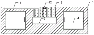
FIG. 2 is a schematic front view of the worktable according to the present invention;
FIG. 3 is a schematic cross-sectional view of a stage according to the present invention;
fig. 4 is a schematic structural view of the protective cover of the present invention.
In the figure: 1. a work table; 2. a first square chute; 3. a collection box; 4. a tool cabinet; 5. a universal wheel; 6. a protective cover; 7. an observation window; 8. a second square chute; 9. a fixed block; 10. a first electric telescopic rod; 11. an arc-shaped splint; 12. a groove; 13. a through hole; 14. an electric slide rail; 15. a movable block; 16. a second electric telescopic rod; 17. a third electric telescopic rod; 18. a sawing motor; 19. a sawing wheel; 20. an acoustical panel.
Detailed Description
The technical solutions in the embodiments of the present invention will be clearly and completely described below with reference to the drawings in the embodiments of the present invention, and it is obvious that the described embodiments are only a part of the embodiments of the present invention, and not all of the embodiments. All other embodiments, which can be derived by a person skilled in the art from the embodiments given herein without making any creative effort, shall fall within the protection scope of the present invention.
Referring to fig. 1-4, the invention provides an aluminum bar sawing machine, comprising a workbench 1 and a protective cover 6, wherein two fixed blocks 9 are fixedly arranged on one side of the top end of the workbench 1, the middle parts of one sides of the two fixed blocks 9 are respectively fixedly connected with the middle parts of one sides of two arc-shaped clamping plates 11 through first electric telescopic rods 10, a plurality of through holes 13 are uniformly arranged in the middle part of the top end of the workbench 1, a first square chute 2 is arranged in the middle part of the front side of the workbench 1, the interior of the first square chute 2 is communicated with the bottom ends of the through holes 13, two sides of the inner wall of the first square chute 2 are respectively connected with two sides of a collecting box 3 in a sliding manner, two electric slide rails 14 are fixedly arranged on the other side of the top end of the workbench 1, the inner walls of the two electric slide rails 14 are respectively connected with the bottom ends of two movable blocks 15 in a sliding manner through slide blocks, the middle parts of, the square spout 8 of second has all been seted up to the both sides side on 1 top of workstation, and the inner wall of two square spouts 8 of second is through the both sides sliding connection of slider with the 6 bottom of protection casing respectively, and one side on 6 inner wall tops of protection casing is fixed and is equipped with third electric telescopic handle 17, and connecting block and the middle part fixed connection who saw cuts 18 tops of motor are passed through to the bottom of third electric telescopic handle 17, saw cut the output shaft of motor 18 through the pivot with saw cut the middle part fixed connection on one side of wheel 19.
Preferably, four corners of the bottom end of the workbench 1 are respectively fixedly provided with a universal wheel 5, so that the aluminum bar sawing machine is convenient to move; tool cabinets 4 are fixedly arranged on two sides of the front surface of the workbench 1 and can be used for placing tools and materials required by sawing of the aluminum bar; the middle part of the top end of the workbench 1 is provided with the groove 12, and the positions of the grooves 12 and the positions of the sawing wheels 19 are arranged in a one-to-one correspondence manner, so that the workbench 1 can be prevented from being scratched by the sawing wheels 19; an observation window 7 is fixedly arranged in the middle of the front surface of the protective cover 6, so that the sawing condition in the protective cover 6 can be observed in real time; the inner wall of the protective cover 6 is fixedly provided with a sound insulation board 20, and a plurality of sound absorption cotton are filled in the sound insulation board 20, so that the noise generated by the sawing motor 18 can be isolated, and the environment is protected; fixed first electric telescopic handle switch that is equipped with in one side of workstation 1, electric slide rail switch and second electric telescopic handle switch, two first electric telescopic handle 10, two electric slide rail 14 and two second electric telescopic handle 16 are respectively through first electric telescopic handle switch, electric slide rail switch and second electric telescopic handle switch and external power supply electric connection, one side of protection casing 6 is fixed and is equipped with third electric telescopic handle switch and saw cuts motor switch, third electric telescopic handle 17 and saw cut motor 18 respectively through third electric telescopic handle switch and saw cut motor switch and external power supply electric connection.
When the aluminum bar sawing machine is used, firstly, the electric slide rail switch is started, the electric slide rail 14 moves the movable block 15 to the rightmost end, then, an aluminum bar extends into the protective cover 6 through the feed inlet of the protective cover 6, then, the first electric telescopic rod switch and the second electric telescopic rod switch are started, the first electric telescopic rod 10 drives the arc-shaped clamping plate 11 to move towards the middle part so as to fix one end of the aluminum bar, then, the second electric telescopic rod 16 also drives the arc-shaped clamping plate 11 to move towards the middle part so as to fix the other end of the aluminum bar, so that the aluminum bar can be fixed firmly, errors are prevented when the aluminum bar is sawed, the quality of the sawed aluminum bar is ensured, after the aluminum bar is fixed, the third electric telescopic rod switch is started, the third electric telescopic rod 17 downwards moves the sawing wheel 19 so that the sawing wheel 19 is contacted with the aluminum bar, and after the sawing wheel 19 is contacted with the aluminum bar, the start saw cuts motor switch, saw cut motor 18 and drive saw cut wheel 19 and rotate, in order to saw cut the operation to the aluminium bar, saw cut the in-process at this aluminium bar and can produce a large amount of sparks and piece, protection casing 6 can keep apart spark and piece in protection casing 6 this moment, in order to prevent that spark and piece from causing the threat to operating personnel's healthy, the piece can get into in the collection box 3 in the spout 2 through-hole 13 simultaneously, be convenient for operating personnel clearance aluminium bar piece, and then can effectively alleviate operating personnel's the amount of labour, treat that the aluminium bar saw cuts the completion back, electronic slide rail 14 removes movable block 15 to leftmost end, the aluminium bar after saw cutting this moment can stretch out from the discharge gate department of protection casing 6, and then accomplish whole saw cutting operation.
In the description of the present invention, it is to be understood that the indicated orientations or positional relationships are based on the orientations or positional relationships shown in the drawings and are only for convenience in describing the present invention and simplifying the description, but are not intended to indicate or imply that the indicated devices or elements must have a particular orientation, be constructed and operated in a particular orientation, and are not to be construed as limiting the present invention.
In the present invention, unless otherwise explicitly specified or limited, for example, it may be fixedly attached, detachably attached, or integrated; can be mechanically or electrically connected; the terms may be directly connected or indirectly connected through an intermediate, and may be communication between two elements or interaction relationship between two elements, unless otherwise specifically limited, and the specific meaning of the terms in the present invention will be understood by those skilled in the art according to specific situations.
Although embodiments of the present invention have been shown and described, it will be appreciated by those skilled in the art that changes, modifications, substitutions and alterations can be made in these embodiments without departing from the principles and spirit of the invention, the scope of which is defined in the appended claims and their equivalents.
Claims (7)
1. The aluminum bar sawing machine comprises a workbench (1) and a protective cover (6), and is characterized in that two fixed blocks (9) are fixedly arranged on one side of the top end of the workbench (1), the middle parts of one sides of the two fixed blocks (9) are fixedly connected with the middle parts of one sides of two arc-shaped clamping plates (11) through first electric telescopic rods (10) respectively, a plurality of through holes (13) are uniformly formed in the middle part of the top end of the workbench (1), a first square sliding chute (2) is formed in the middle of the front side of the workbench (1), the inner part of the first square sliding chute (2) is communicated with the bottom ends of the through holes (13), the two sides of the inner wall of the first square sliding chute (2) are respectively in sliding connection with the two sides of a collecting box (3), two electric sliding rails (14) are fixedly arranged on the other side of the top end of the workbench (1), and the inner walls of the two electric sliding rails (14) are respectively in sliding connection with, two the middle part fixed connection of second electric telescopic handle and two other arc splint (11) one side is do not passed through to the well part of movable block (15) one side, the square spout of second (8), two have all been seted up to the both sides side on workstation (1) top the inner wall of the square spout of second (8) is through the both sides sliding connection of slider with protection casing (6) bottom respectively, one side on protection casing (6) inner wall top is fixed and is equipped with third electric telescopic handle (17), the middle part fixed connection on connecting block and saw cut motor (18) top is passed through to the bottom of third electric telescopic handle (17), the output shaft that saw cut motor (18) is through the middle part fixed connection of pivot and saw cutting wheel (19) one side.
2. The aluminum bar sawing machine of claim 1, wherein: four corners of the bottom end of the workbench (1) are fixedly provided with universal wheels (5).
3. The aluminum bar sawing machine of claim 1, wherein: and tool cabinets (4) are fixedly arranged on two sides of the front surface of the workbench (1).
4. The aluminum bar sawing machine of claim 1, wherein: the middle part of the top end of the workbench (1) is provided with a groove (12), and the position of the groove (12) and the position of the sawing wheel (19) are arranged in a one-to-one correspondence manner.
5. The aluminum bar sawing machine of claim 1, wherein: and an observation window (7) is fixedly arranged in the middle of the front surface of the protective cover (6).
6. The aluminum bar sawing machine of claim 1, wherein: the inner wall of protection casing (6) is fixed and is equipped with acoustic celotex board (20), the inside packing of acoustic celotex board (20) has a plurality of to inhale the sound cotton.
7. The aluminum bar sawing machine of claim 1, wherein: one side of workstation (1) is fixed and is equipped with first electric telescopic handle switch, electric slide rail switch and second electric telescopic handle switch, two first electric telescopic handle (10), two electric slide rail (14) and two second electric telescopic handle (16) are respectively through first electric telescopic handle switch, electric slide rail switch and second electric telescopic handle switch and external power supply electric connection, one side of protection casing (6) is fixed and is equipped with third electric telescopic handle switch and saw cuts motor switch, third electric telescopic handle (17) and saw cut motor (18) respectively through third electric telescopic handle switch and saw cut motor switch and external power supply electric connection.
Priority Applications (1)
| Application Number | Priority Date | Filing Date | Title |
|---|---|---|---|
| CN201911352820.6A CN111014817A (en) | 2019-12-25 | 2019-12-25 | Aluminum bar sawing machine |
Applications Claiming Priority (1)
| Application Number | Priority Date | Filing Date | Title |
|---|---|---|---|
| CN201911352820.6A CN111014817A (en) | 2019-12-25 | 2019-12-25 | Aluminum bar sawing machine |
Publications (1)
| Publication Number | Publication Date |
|---|---|
| CN111014817A true CN111014817A (en) | 2020-04-17 |
Family
ID=70213485
Family Applications (1)
| Application Number | Title | Priority Date | Filing Date |
|---|---|---|---|
| CN201911352820.6A Pending CN111014817A (en) | 2019-12-25 | 2019-12-25 | Aluminum bar sawing machine |
Country Status (1)
| Country | Link |
|---|---|
| CN (1) | CN111014817A (en) |
Cited By (3)
| Publication number | Priority date | Publication date | Assignee | Title |
|---|---|---|---|---|
| CN112548218A (en) * | 2020-12-29 | 2021-03-26 | 温州宏刚科技有限公司 | Cutting device of metal component |
| CN113664289A (en) * | 2021-09-07 | 2021-11-19 | 安徽欣叶安康门窗幕墙股份有限公司 | Single-end saw cutting noise-reducing dustproof device |
| CN114178620A (en) * | 2021-11-24 | 2022-03-15 | 安徽南都华铂新材料科技有限公司 | Waste lithium ion battery shell regenerating device |
Citations (6)
| Publication number | Priority date | Publication date | Assignee | Title |
|---|---|---|---|---|
| US4865300A (en) * | 1988-01-29 | 1989-09-12 | Borzym John J | Tube handling apparatus |
| JPH07164237A (en) * | 1993-12-08 | 1995-06-27 | Mitsubishi Heavy Ind Ltd | Pipe cutter |
| CN207577542U (en) * | 2017-12-01 | 2018-07-06 | 上海景朋建设工程有限公司 | A kind of hydraulic engineering adjustable pipeline cutting equipment |
| CN207982830U (en) * | 2018-02-14 | 2018-10-19 | 天津市帅超激光工程技术有限公司 | A kind of metal tube drilling tool |
| CN109759854A (en) * | 2019-03-23 | 2019-05-17 | 江西师范大学 | A kind of tubing automatic machining device |
| CN209223260U (en) * | 2018-06-01 | 2019-08-09 | 上海尔吉其门窗幕墙系统有限公司 | Cutting machine is used in a kind of processing of aluminium sheet |
-
2019
- 2019-12-25 CN CN201911352820.6A patent/CN111014817A/en active Pending
Patent Citations (6)
| Publication number | Priority date | Publication date | Assignee | Title |
|---|---|---|---|---|
| US4865300A (en) * | 1988-01-29 | 1989-09-12 | Borzym John J | Tube handling apparatus |
| JPH07164237A (en) * | 1993-12-08 | 1995-06-27 | Mitsubishi Heavy Ind Ltd | Pipe cutter |
| CN207577542U (en) * | 2017-12-01 | 2018-07-06 | 上海景朋建设工程有限公司 | A kind of hydraulic engineering adjustable pipeline cutting equipment |
| CN207982830U (en) * | 2018-02-14 | 2018-10-19 | 天津市帅超激光工程技术有限公司 | A kind of metal tube drilling tool |
| CN209223260U (en) * | 2018-06-01 | 2019-08-09 | 上海尔吉其门窗幕墙系统有限公司 | Cutting machine is used in a kind of processing of aluminium sheet |
| CN109759854A (en) * | 2019-03-23 | 2019-05-17 | 江西师范大学 | A kind of tubing automatic machining device |
Cited By (3)
| Publication number | Priority date | Publication date | Assignee | Title |
|---|---|---|---|---|
| CN112548218A (en) * | 2020-12-29 | 2021-03-26 | 温州宏刚科技有限公司 | Cutting device of metal component |
| CN113664289A (en) * | 2021-09-07 | 2021-11-19 | 安徽欣叶安康门窗幕墙股份有限公司 | Single-end saw cutting noise-reducing dustproof device |
| CN114178620A (en) * | 2021-11-24 | 2022-03-15 | 安徽南都华铂新材料科技有限公司 | Waste lithium ion battery shell regenerating device |
Similar Documents
| Publication | Publication Date | Title |
|---|---|---|
| CN111014817A (en) | Aluminum bar sawing machine | |
| CN210452017U (en) | Waste collection and protection device of vertical machining center | |
| CN216461983U (en) | Precise numerical control planer type milling machine capable of cutting at high speed | |
| CN216968063U (en) | Sliding table saw convenient to remove bits | |
| CN212398944U (en) | Metal product cutting device | |
| CN115625372B (en) | Board cutting device is used in automatically controlled cabinet production | |
| CN216828609U (en) | Cast member's runner cutting device | |
| CN211306568U (en) | Automatic pay-off circular sawing machine | |
| CN215967616U (en) | Machining perforating device with location structure | |
| CN216680458U (en) | Accurate mechanical engineering is with numerical control cutting off machine who effectively avoids sweeps to splash | |
| CN216099462U (en) | Numerical control groove broaching equipment for customized furniture board processing | |
| CN212443508U (en) | Mechanical metal cutting device convenient for recovering scraps | |
| CN213614492U (en) | Cutting device is used in angle aluminium production | |
| CN211890026U (en) | Milling machine processing device capable of preventing scraps from splashing | |
| CN211940044U (en) | Milling machine with dust collection function | |
| CN211729544U (en) | Multifunctional electric tool for woodworker | |
| CN113649829A (en) | Gear type oil groove cutting device based on automobile part machining lathe | |
| CN216298078U (en) | Hollow steel pipe mills waste treatment device | |
| CN219427009U (en) | Sawing machine piece treatment equipment | |
| CN217530090U (en) | Light high-strength motor casing processing milling machine | |
| CN209954313U (en) | Metal cutting machine | |
| CN215746854U (en) | Chip removal device for gear hobbing machine | |
| CN221774022U (en) | Turning and milling compound machine tool with tool magazine | |
| CN219402872U (en) | Protection device for laser cutting machine | |
| CN213530970U (en) | Cutting device for sheet metal part machining |
Legal Events
| Date | Code | Title | Description |
|---|---|---|---|
| PB01 | Publication | ||
| PB01 | Publication | ||
| SE01 | Entry into force of request for substantive examination | ||
| SE01 | Entry into force of request for substantive examination | ||
| RJ01 | Rejection of invention patent application after publication |
Application publication date: 20200417 |
|
| RJ01 | Rejection of invention patent application after publication |